Solutions for Advancing Communications MODEL MB-R OWNER’S MANUAL Model MB-R AVIATION BAND VHF RADIO RECEIVER/TRANSMITTER Base Station (118.000-136.975 MHz) www.mentorradio.
INTRODUCTION The Mentor Radio Model MB-R receives and transmits on up to six discrete channels in the VHF aviation band between 118 and 136 Mhz. It is a base transceiver for air carriers, airports, fixed-base operators, corporate flight departments, hospital helipads, etc. The unit is a separate M15 radio and a PA-25 power amplifier, which produces 10 watts of transmitter RF power. There is also a connection for connecting an aircraft standard microphone using a 3/16” microphone plug.
INSTALLATION Select a desk, counter, shelf or table top on which to place the Model MB-R, convenient to the operator but inaccessible to unauthorized persons. Allow several inches of space behind and above the unit for air circulation; this is especially important if heavy use is anticipated. Plug the line cord into a properly grounded standard 3-wire electrical outlet. If an extension cord is needed, a 3-wire type should be used.
The coaxial cable should be terminated at the radio end by an “N” type connector. The connector should be installed by a person skilled in this operation. This connector plugs into the mating connector (type “N”) on the rear of the MB-R. Be sure to turn the ring with the internal threads CW until the connection is firmly made. At the antenna end, if there is no similar connector, any unshielded center lead should be no longer than 2 inches (5 cm.
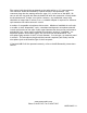
MB-R ASSEMBLY/INSTALLATION Assembly required before first use. Remove all packing material. Connect UHF connector and power harness as shown. MB-R Rear View Antenna Connector Connect the UHF connector to rear panel receptacle as shown. Connect power harness to rear panel receptacles as shown. Optionally connect remote cable if provided.
OPERATION The Model MB-R is turned on and off by the rocker switch near the lower left rear corner on the base. The volume control knob (marked VOL) adjusts speaker loudness to the level preferred by the operator. The volume control may have a built-in, onoff switch. THE VOLUME CONTROL SWITCH SHOULD BE LEFT ON AT ALL TIMES. Turn the unit on and off using the switch in the rear of the unit. The volume control does not affect transmitter operation.
MICROPHONE TECHNIQUE 1. 2. 3. Hold microphone close to mouth (1/4 inch or 1/2 cm) Enunciate clearly Speak with average loudness-not softly (but don’t shout) If a non-noise canceling pedestal (dispatcher’s) microphone is used, it is not as essential to hold the microphone close to the mouth. These microphones will pick up more background and room noise, including the voices of other persons talking, radios playing, etc. On the front panel a red LED lights when transmitting.