TS2000 (V2+) INTRUDER ALARM CONTROL SYSTEM USER MANUAL
TS2000 (V2+) User Manual COPYRIGHT All rights reserved. No part of the information contained in this publication may be reproduced or copied by any means without the prior written permission of Menvier Security Ltd © Menvier Security Ltd 1991 REVISION STATUS ISSUE DATE PAGE DETAILS 01 02 02 Oct 91 Feb 92 JUL 93 All 2-6; 3-4/5; First Issue for S/W V2.
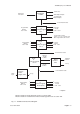
TS2000 (V2+) User Manual CONTENTS 1 1.1 1.2 1.3 1.4 1.5 Fig 1-1 OVERVIEW Introduction Equipment Control Panel Options Additional Equipments Remote Data Transfer Schematic Block Diagram Page 1-1 Page 1-1 Page 1-1 Page 1-2 Page 1-2 Page 1-3 2 2.1 2.2 2.3 2.4 2.5 2.6 2.7 2.8 2.9 2.10 2.11 2.
TS2000 (V2+) User Manual 4 4.1 4.2 4.3 4.4 4.5 4.6 4.7 4.8 4.9 4.10 4.11 4.12 4.13 4.14 4.15 4.
TS2000 (V2+) User Manual INTRUDER ALARM CONTROL SYSTEM TS2000 (S/W V2+) 1 OVERVIEW 1.1 Introduction The Intruder Alarm Control System TS2000 is provided for large domestic and general commercial intruder systems conforming to BS 4737 part 1 1986.
TS2000 (V2+) User Manual (4) 1.4 1.4.1 1.4.2 1.4.3 1.4.4 1.4.5 1.4.6 1.5 Modem type DC3M (Digimodem): Will transfer data over PSTN lines to and from any suitable equipment such as a computer terminal. When activated the system will dial one or two telephone numbers and will be capable of transferring all commissioning information, Event Log data etc to and from a remote maintenance centre.
TS2000 (V2+) User Manual PSTN Lines* CONTROL PANEL Mains input 240V 50Hz Other Option Outputs Programmable Option Outputs Control Network Cable Node or Remote Keypad No 1 Programmable Outputs S001 - S004 Detection Circuits C001 - C004 Control Network Cable Cable: 6 or 8 core 7/0.2mm2 min. Max length 100m between units.
TS2000 (V2+) User Manual 2 OPERATIONAL FACILITIES 2.1 2.1.1 Introduction The system operates in two states which may be considered as 'Monitoring', when the system responds to circuit activations, and 'Operator Controlling' which requires the operator to enter a passcode and to operate a REM keypad.
TS2000 (V2+) User Manual (2) Master; (3) Manager; (4) Standard S (system); (5) Standard W (ward); (6) Restricted; (7) Not Used; The highest level is (1) and the lowest is (6) so that the Engineer can carry out nearly all operations but the Manager can only carry out the operations allocated to passcode levels Manager, Standard and Restricted (Fig 3-1). The last passcode (7) will not allow access to the system. 2.3.
TS2000 (V2+) User Manual (a) (9) (10) (11) (12) (13) (14) (15) (16) (17) When momentarily activated during Setting, after use of the Last Exit, will complete the Setting process if it has been programmed to do so (para 3.2); (b) If activated momentarily during Timed Setting it will truncate the time and immediately complete the Setting process (para 3.
TS2000 (V2+) User Manual The System Activated Outputs may be allocated to any Node (NU or REM) output or the Panel (CP) outputs. They are designated by their function and may be programmed to be active if required. The following are available: (1) Alarm: A system alarm is present (para 2.1); (2) P.A.: A Personal Attack circuit or a Duress Alarm has been activated (para 2.4); (3) Set: The system is set (para 3.1.2); (4) Fire: A Fire circuit has been activated (para 2.4.
TS2000 (V2+) User Manual 2.6.5 2.7 2.7.1 2.7.2 2.7.3 2.8 2.8.1 (6) Exit: The relevant Ward (with WCU) exit procedure has been initiated (para 3.3); (7) Entry: The relevant Ward (with WCU) entry procedure has been initiated (para 3.4); Ward outputs (1), (2), (3) and (6) above must be programmed and connected to the WCU if one is fitted.
TS2000 (V2+) User Manual (7) (8) (9) (10) (11) (12) 2.9 2.9.1 Second Entry Time: Is an additional period of time allowed for entering protected premises that is activated after the First Entry Time has expired during which limited alarms will be activated. Default value is 30 seconds; Communicator Delay Time: This is the delay time before the Digital Communicator is activated when a Ward Alarm occurs which is not required to be communicated immediately.
TS2000 (V2+) User Manual (8) (9) (10) 2.10 2.10.1 2.10.2 2.11 2.11.1 2.11.2 2.11.3 2.11.4 2.12 2.12.1 2.12.2 2.12.3 2.12.4 2.12.5 Re-arm: This may be set to Auto or to Manual. Auto Re-arm means that at the end of the Bell Duration period the circuit will repeat the alarm, if the alarm condition is still present, or if it re-occurs. Manual re-arming will inhibit the circuit, once it has generated an alarm, until the panel is reset.
TS2000 (V2+) User Manual 3 SYSTEM MENUS 3.1 Introduction A series of Menus are provided which determine all the actions that may be taken to programme or control the system. There are two entry points to the Menus, depending upon whether an Engineer or a User passcode is entered, and the Menus may be stepped through sequentially using the keyboard up and down arrow keys or accessed directly by entering the Menu number for Menu items 1 to 9 (Fig 3 - 1). 3.2 3.2.
TS2000 (V2+) User Manual 3.4 3.4.1 3.4.2 Unsetting the System The System may be unset in a number of ways: (1) Entry Procedure: This is normally initiated by using the access designated as the Last Exit. This action starts the Entry Timer (para 2.8) and the Sounder will pulse at an increasing rate. The User should complete the unsetting by going to a REM and entering a passcode within the first entry time (para 2.
TS2000 (V2+) User Manual The omitted circuits will be automatically enabled when the system or relevant ward is unset unless the ward is key controlled. 3.
TS2000 (V2+) User Manual used to enable Panel or Node outputs (para 2.6) at the times set and there is a manual override facility. 3.17 Alter Time Lock (Menu 14) The Time Lock is used to restrict Setting and Unsetting of the System or Ward 1 to certain times so that they must be Set before a certain time and may not be Unset until after a certain time. A Warning Time, a Lock Time, and an Unlock Time may be defined and then allocated to selected days of the week.
TS2000 (V2+) User Manual (11) (12) Double Knock time: time period of double knock window; Line Fault d: delay before line fault alarm. 3.23 Define Panel Modes (Menu 20) The system Modes of operation (para 2.
TS2000 (V2+) User Manual (4) this will be indicated by changing the end of line links at the old end unit and the new unit, also the system will not need to re-number all units, circuits and outputs. Having installed a unit the circuits and outputs will need to be programmed; Delete Node: This procedure is the same as installing a Node or REM except that the unit is removed instead of being installed. 3.
TS2000 (V2+) User Manual Menu No User Eng Menu Level Ref Para 1 Start Set Sequence 1, 2, 3, 4, 5, 6 432; 433 2 Unset Wards 1, 2, 3, 4, 5, 6 3.5 3 View Circuits 1, 2, 3, 4, 5, 6 3.6 4 View Event Log 1, 2, 3 3.7 5 Select Walk Test 1, 2, 3, 4, 5 3.8 6 Select Bell Test 1, 2, 3, 4, 5 3.9 7 Omit/Enable Circuit 1, 2, 3 3.10 8 Use Chime Facility 1, 2, 3 3.11 9 Use the Printer 1, 2, 3 3.12 10 Alter Clock 1, 2 3.13 11 Alter Passcode 1, 3, 4, 5, 6 3.
TS2000 (V2+) User Manual 4 OPERATING THE SYSTEM 4.1 4.1.1 Introduction The system is controlled from a REM by using the keypad to control Menus. It is convenient to consider the Menus as three groups: (1) Menus 1 and 2: Used by the Engineer and the Users to set the System and to set and unset Wards; (2) Menus 3 to 13, 23 and 25: Provide facilities the Engineer and certain Users to modify system operation and to monitor the system; (3) All other Menus: Used by the Engineer to programme the system.
TS2000 (V2+) User Manual 4.2 Set System and all Available Wards (without WCU). Circuits may be Omitted STEP ACTION DISPLAY REMARKS 1 - SYSTEM UNSET (date) (time) System and all wards are unset 2 Enter passcode Press YES to START SET SEQUENCE Press YES to continue to step 3A or to step 4 or to step 5A. Press 0 to quit. (Press NO to go to other Menus) 3A YES SET?:- System (9) & Ward 1 (to) 8 Only displayed if Wards are defined and only Wards with circuits will be displayed.
TS2000 (V2+) User Manual 4.4 Set System and Some or No Wards (without WCU). Circuits may be Omitted STEP ACTION DISPLAY REMARKS 1 - SYSTEM UNSET (date) (time) System and all Wards are unset 2 Enter passcode Press YES to START SET SEQUENCE Press YES to continue. Press 0 to quit. (Press NO to go to other Menus) 3 YES SET?:- System (9) & Ward 1 (to) 8** Only Wards with circuits will be displayed. Enter numbers of wards not to be set - figures will 'toggle'.
TS2000 (V2+) User Manual 4.6 Set System and Some or No Wards with Wards Previously Set (no WCU) and No Circuits Omitted STEP ACTION DISPLAY REMARKS 1 - SET 1 (to) 8 (date) (time) Only the Wards indicated are set. Enter passcode for access 2 Enter passcode Press YES to START SET SEQUENCE Press YES to continue then go to step 3A or 4. Press 0 to quit. (Press NO to Unset wards) 3A YES SET? :- SYSTEM (9) & Ward 1 (to) 8 (or step 4) Only if some wards are not set.
TS2000 (V2+) User Manual 4.9 Set More Wards with Wards Previously Set (no WCU) and With Circuits Omitted STEP ACTION DISPLAY 1 - SET (date) (time) 2 Enter passcode Press YES to START SET SEQUENCE Press YES to continue. Press 0 to quit. (Press NO to Unset wards) 3 YES OMITTED CIRCUITS Press YES to view Circuits have been omitted. Press YES to view them and then to continue or NO/0 to continue 4 NO SET? :- SYSTEM (9) & Ward 1 (to) 8 (or step 4) Wards not set shown.
TS2000 (V2+) User Manual 4.11 Unset Wards with Circuits Omitted STEP ACTION DISPLAY REMARKS 1 - SET(date) 2 Enter passcode Press YES to START SET SEQUENCE Press NO to unset wards. Press 0 to quit. (Press YES to set - see para 4.2) 3 NO Press YES to UNSET WARDS Press YES to unset wards. Press 0 to quit. (Press NO for Menu Mode) 4 YES UNSET WARDS? :1 (to) 8 Press YES to unset all the wards displayed. Enter numbers of wards not to be unset - go to step 7. Press 0 to return to step 3.
TS2000 (V2+) User Manual 4.13 Clearing Circuits Omitted STEP ACTION DISPLAY REMARKS 1 - CIRCUITS OMITTED (date) (time) Circuit or circuits have been omitted and action is required 2 Enter passcode Press YES to START SET SEQUENCE Enter 7 to Omit or enable circuits. (Press Yes to view circuits and go to set sequence -Para 5.2) 3 7 Press YES to OMIT/ENABLE CIRCUITS Press YES to change omitted circuits.
TS2000 (V2+) User Manual 5 PROGRAMMING THE SYSTEM 5.1 5.1.1 Introduction The system is initially programmed by an Engineer during commissioning but changes to programmed data may also be made by the Users. Programming may also be done using the Remote Data Transfer Facility. All the programming Menus are listed here in a step by step sequence (see Fig 3 - 1). The general procedure is to enter a Passcode, select the Menu then enter data etc..
TS2000 (V2+) User Manual 5.2 View Circuits (Menu 3) STEP ACTION DISPLAY REMARKS 1 No* Press to VIEW CIRCUITS Press YES to View Circuits. Press NO to go to Event Log menu. Use arrow keys to step through menus. Press 0 to quit 2 YES CCT >001 Healthy TYPE/TEXT Press YES to step to nexr circuit. Use arrow keys to step through circuits. Enter figures to select new circuit. Press NO to return to step 1 3 YES CCT >002 Healthy TYPE/TEXT Press YES to step to nexr circuit.
TS2000 (V2+) User Manual 5.5 Select Bell Test (Menu 6) STEP ACTION DISPLAY REMARKS 1 No* Press to SELECT BELL TEST Press YES to carry out Bell Test. Press NO to go to Omit/Enable Circuits menu. Use arrow keys to step through menus.
TS2000 (V2+) User Manual 5.7 Chime Facility (Menu 8) STEP ACTION DISPLAY REMARKS 1 No* Press to USE CHIME FACILITY Press YES to use Chime Facility. Press NO to go to use the Printer. Use arrow keys to step through menus. Press 0 to quit 2 YES Press YES to ALTER CHIME CIRCUITS Press YES to alter circuits that chime. Press NO to go to Enable System Chime. Press 0 to go to step 1.
TS2000 (V2+) User Manual 5.8 Use The Printer (Menu 9) STEP ACTION DISPLAY REMARKS 1 NO* Press to USE THE PRINTER Press YES to use the Printer. Press NO to go to Alter Clock menu. Use arrow keys to step through menus. Press 0 to quit 2 YES Press YES to PRINT ALL Press YES to print everything except the Event Log and the Dictionary. Press NO to go to Print Circuits. Use arrow keys to step through print menus. Press 0 to go to step 1. Printer will be activated and display remain.
TS2000 (V2+) User Manual 5.9 Alter Clock (Menu 10) STEP ACTION DISPLAY REMARKS 1 NO* Press to ALTER CLOCK Press YES to set system date and time. Press NO to go to Alter Passcode menu. Use arrow keys to step through menus. Press 0 to quit 2 YES Date is >DD/MM/YYYY time is hh:mm:ss Enter figures to change indicated date or time if required then press YES to accept. Press NO to reset figure to 01. Use arrows to step through figures 3 YES Date is DD>MM/YYYY time is hh:mm:ss Day accepted.
TS2000 (V2+) User Manual 5.11 Define Users (Menu 12) STEP ACTION DISPLAY REMARKS 1 NO* Press to DEFINE USERS Press YES to Define Users. Press NO to go to Alter Time Switch menu. Use arrow keys to step through menus. Press 0 to quit 2 YES Press YES to ALTER USER TYPE Press YES to alter User type. Press NO to go to Alter Passcode menu. Press 0 to return to step 1. Use arrow keys to step through menus 3 YES USER >01 defined as ENGINEER Press YES to accept and go to next User.
TS2000 (V2+) User Manual 5.11 Define Users (Menu 12) (continued) STEP ACTION DISPLAY REMARKS 13 (1234) Code confirmed OK Press any key Press any key 14 YES ALTER PASSCODE Enter User No >02 Enter figures or use arrow keys to change User number. Continue steps10 to 13 for other Users if required. Press NO to change to 00. Enter 00 to quit 15 00 YES to continue Invalid No >00 Press YES to continue.
TS2000 (V2+) User Manual 5.12 Alter Time Switch (Menu 13) STEP ACTION DISPLAY REMARKS 1 NO* Press to ALTER TIME SWITCH Press YES to alter Time Switch. Press NO to go to Alter Time Lock menu. Use arrow keys to step through menus. Press 0 to quit 2 YES ALTER TIME SWITCH >ON TIME [1] hh:mm Press YES to retain this time switch function. Press No to got to Off Time. Use arrow keys to step through times 3 YES ALTER TIME SWITCH ON TIME [1] >hh:mm Press NO to enter 00.
TS2000 (V2+) User Manual 5.13 Alter Time Lock (Menu 14) STEP ACTION DISPLAY REMARKS 1 NO* Press to ALTER TIME LOCK Press YES to alter Time Lock. Press NO to go to Define Circuits menu. Use arrow keys to step through menus. Press 0 to quit 2 YES ALTER TIME LOCK >UNLOCK TIME hh:mm Press YES to retain this Time function. Press No to got to Lock Time. Use arrow keys to step through times 3 YES ALTER TIME LOCK UNLOCK TIME >hh:mm Press NO to enter 00.
TS2000 (V2+) User Manual 5.14 Define Circuits (Menu 15) STEP ACTION DISPLAY REMARKS 1 Eng Passcode* Press to DEFINE CIRCUITS Press YES to Define Circuits. Press NO to go to Define Outputs menu. Use arrow keys to step through menus. Press 0 to quit 2 YES 001< CIRCUIT TYPE * * * * * Press YES to accept displayed circuit type, attribute and ward. Press NO to change. Use arrow keys to step through circuits.
TS2000 (V2+) User Manual 5.15 Define Outputs (Menu 16) STEP ACTION DISPLAY REMARKS 1 NO** Press to DEFINE OUTPUTS Press YES to Define Outputs. Press NO to go to Review Wards menu. Use arrow keys to step through menus. Press 0 to quit 2 YES Press to ALTER PANEL OUTPUTS Press YES to alter PANEL outputs. Press NO to alter NODE outputs then YES to continue 3 YES O/P >001 (Panel)* is (Output Type) Press YES to accept displayed Panel or Node output configuration and go to next output.
TS2000 (V2+) User Manual 5.17 Define Ward Alarms (Menu 18) STEP ACTION DISPLAY REMARKS 1 NO* Press to DEFINE WARD ALARMS Press YES to define Ward Alarms. Press NO to go to Define Timers menu. Use arrow keys to step through menus. Press 0 to quit 2 YES Ward 1 alarm is Bells only Press YES to accept displayed information and go to next ward. Press NO to change the Ward Alarm response. Use arrow keys to step through Wards.
TS2000 (V2+) User Manual 5.19 Define Panel Modes (Menu 20) STEP ACTION DISPLAY REMARKS 1 NO* Press to DEFINE PANEL MODES Press YES to Define Panel Modes. Press NO to go to Test Facilities menu. Use arrow keys to step through menus. Press 0 to quit 2 YES At end of exit, set with 'Last Exit' Press YES to accept or NO to change to 'Exit Terminator' or 'Exit Timer' then YES to accept. Use arrow keys to step through Exit modes.
TS2000 (V2+) User Manual 5.20 Use Test Options (Menu 21) STEP ACTION DISPLAY REMARKS 1 NO* Press to USE TEST OPTIONS Press YES to use Test Facilites menu. Press NO to go to Network Options menu. Use arrow keys to step through menus. Press 0 to quit 2 YES Press YES to PUT CIRCUIT ON TEST Press YES to select a circuit for test. Press NO to go to Start Timed Test (step 9).
TS2000 (V2+) User Manual 5.20 Use Test Options (Menu 21) (continued) STEP ACTION DISPLAY REMARKS 21 NO Press to SEE VERSION Press YES to see Software and Dictionary version numbers. Press NO to go to Alter Reset Calculation. Use arrow keys to step through menus. Press 0 to quit 22 YES SW XXX.XX DIC XXX.XX Press YES to accept and go to next option. Press 0 to return to step 1 23 YES Press YES to ALTER RESET CALC Press YES to alter Remote Reset facility reset calculation caonstant.
TS2000 (V2+) User Manual 5.22 Use Network Options (Menu 22) (continued) STEP ACTION DISPLAY REMARKS 12 YES Press YES to INSERT NEW NODE Press NO to go to Delete Node. Press YES to go to step 10. Press 0 to go to step 1 13 NO Press YES to DELETE NODE Press YES to delete a Node. Press NO to go to step 2. Press 0 to go to step 1 14 YES Delete before >01 Delete Node Press YES to delete indicated Node.
TS2000 (V2+) User Manual 5.24 Install DC3 (Digicom) (Menu 24) STEP ACTION DISPLAY REMARKS 1 NO* Press to INSTALL DC3 Press YES to program Digital Communicator. Press NO to go to Start Set Sequence menu. Use arrow keys to step through menus. Press 0 to quit 2 YES DC3 used as Digicom YES or NO Press YES or NO as required.. If No go to step 18 and Digicom will not function 3 YES PLEASE WAIT Loading DC3 Digicom data 4 - PHONE NO 1 0000000000000000** Last number entered displayed.
TS2000 (V2+) User Manual Issue 02 Feb 92 Page 5 - 19
TS2000 (V2+) User Manual 5.24 Install DC3 (Modem) (Menu 24 continued) STEP ACTION DISPLAY REMARKS 19 PLEASE WAIT Loading Modem data MODEM NO 000000000000000000** Old number displayed. Enter figures of required number. Press NO to clear all numbers Press YES to accept displayed number . Press YES to accept displayed number. YES 20 21 (digits) MODEM NO (digits) 22 YES SYSTEM NO 0000 Old number displayed. Enter figures of required number. Press NO to clear the number.