SD1+ Speech Dialler SD1+ SD1+ A 1 2 3 B 4 5 6 C 7 8 9 D ENT 0 ESC Installation Instructions
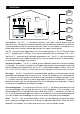
1. Overview A B C Tel No 1 D Auxiliary Input Telephone Tel No 2 1 3 4 2 UNSET TAMPER FINAL EXIT 1 4 2 5 7 8 0 HOME 3 6 9 AWAY 5 SD1+ A 1 2 B 4 5 C 7 8 3 9 D ENT 0 ESC 6 Tel No 3 BT Line Control Panel Speech Dialler Tel No 4 Connections: The SD1+ is connected between the alarm control panel and the telephone line. It behaves like another extension to the telephone and does not affect its normal operation or that of any other extension fitted.
2. Installation Requirements The SD1+ has been designed to be connected to an intruder alarm control panel or similar. The control panel must have an auxiliary power output of between 11.5V and 14V, and the ability to provide a minimum of 100mA. The unit is supplied with a 2 metre telephone lead which will plug directly into any standard BT socket and it is therefore recommended that the unit is sited as near to a BT telephone socket as possible.
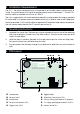
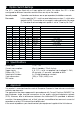
5. SD1+ Connections Before any connections are made to the SD1+ remove the power (battery and 240V mains) from the control panel. Connections are provided as follows: TRIG A: When triggered, the unit starts the dialling sequence and sends message A. TRIG B: When triggered, the unit starts the dialling sequence and sends message B. TRIG C: When triggered, the unit starts the dialling sequence and sends message C.
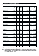
6. Control Panel Connections The table below shows the connection details to various control panels. Control Panel TRIG A Fire TRIG B PA TRIG C Alarm Polarity Supply + Supply - Trigger Type Menvier TS400/TS410 Zone 4 Zone 5 ALM - Aux + Aux - 0V app. Menvier TS510 N/A OP 2 * OP 1 * + Aux + Aux - 12V app. Menvier TS690R OP 1 OP 2 OP 3 - Aux + Aux - 0V app. Menvier TS690/TS700 Digi 1 Digi 2 Digi 3 - Aux + Aux - 0V app.
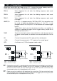
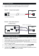
7. BT. Connections 1. Connect telephone line using one of the methods shown below: 2. Replace the plastic cover over the telephone line connections. Method 1 - Using the lead supplied SD1+ White Red A B Standard BT telephone plug Method 2 - Hard wired connections BT Master Jack (NTE5) User accessible connections Cable type 1/0.5mm CW1308 6 5 4 White/Blue 3 2 1 SD1+ Blue/White A B 8. Commissioning and Testing 1.
9. Option Switch Settings The SD1+ may be fitted with a 4-way option bit switch, this allows the SD1+ to be configured for different countries and for either security or fire mode: Security mode Operation and features are as per operators/Installation manuals. Fire mode In this mode the SD1+ only has one telephone number (1), which also defaults to 999. The number of messages is reduced to one (Message 0). The default acknowledgment option is set to “Clear by No One”.
12. Troubleshooting Guide Problem The unit will not dial out. Cause Number incorrectly dialled Action Check the telephone number you are calling has been entered correctly. Cause If the SD1+ is connected to a PABX system you may require a pause after dialling the first digit. Action Program a pause in the telephone number (see “Operating Instructions”). If this does not solve the problem the SD1+ must be connected to a direct telephone line. Cause Incorrect telephone line connections.
SD1+ SD1+ SD1+ A 1 2 3 B 4 5 6 C 7 8 9 D ENT 0 ESC
Contents Getting Started: SD1+ Menu Options . . . . . . . . . . . . . . . . . . . . . . . . . . . . . . . . . . . . . . . . . . . . . 1 Overview . . . . . . . . . . . . . . . . . . . . . . . . . . . . . . . . . . . . . . . . . . . . . . . . . . . . . . . . . . . . . . . . . . . 2 Connections. . . . . . . . . . . . . . . . . . . . . . . . . . . . . . . . . . . . . . . . . . . . . . . . . . . . . . . . . . . . . . . 2 Passcode . . . . . . . . . . . . . . . . . . . . . . . . . . . . . . . . . . . . . . . . . .
Getting Started: SD1+ Menu Options All of the SD1+ menu options are accessed by entering the user passcode (default 1234). These menu options allow all the necessary programming of the SD1+ and are selected by pressing the relative "Hot Key" as shown in the table below. A summary of menu options and their relative "Hot Key" is also shown to the right.
Overview B A C Tel No 1 D Auxiliary Input Telephone Tel No 2 1 3 4 2 UNSET TAMPER FINAL EXIT 1 4 2 5 7 8 0 HOME 3 6 9 AWAY 5 SD1+ A 1 2 B 4 5 C 7 8 9 D ENT 0 ESC 3 6 Tel No 3 BT Line Control Panel Speech Dialler This product is manufactured to meet all European Economic Area Tele-communication networks requirements. Connections The SD1+ is connected between the alarm control panel and the telephone line.
Call Abort The SD1+ can be programmed so that if it is accidentally triggered, the call can be aborted. Once aborted, the dialler will stop dialling out immediately. The SD1+ can be aborted by one of the following methods: when a signal is applied to the abort input, when the input that triggered the unit is removed, or when the user passcode is entered. When an abort is performed by the code, the display shows " " as visual confirmation of the abort being carried out (a chime tone will also be heard).
Programming: Initialising The SD1+ When you power up the SD1+ for the first time, a factory restart is required. This involves shorting out the factory restart pins (JP2) whilst applying power to the unit (please refer to the installation instructions for details). The display will show “ ”, this indicates that the memory is blank (i.e., all telephone numbers and " is messages are not programmed). Once it is programmed, " displayed instead.
Changing Your Passcode Type The SD1+ requires a passcode to be entered to allow access to the ), but program menus. This passcode is normally 4 digits ( can be changed to 6 digits ( ). The default user passcode is 1234. If the passcode is changed from 4 to 6 digits, the last two digits of the code will default to (00) i.e. 1234 will now become 1234 00. 1. Ensure that the SD1+ is initialised and the display is showing “ ” (see page 4). ???? READY 2 + + ”.
Call Routing Messages A, B, C or D can be programmed so that they only report to certain telephone numbers i.e. Message A might report to telephone numbers 1, 3 & 4 but NOT to number 2 ( ). 1. Ensure that the SD1+ is initialised and the display is showing ” (see page 4). “ 2. Press 7 and the display will show “ SD1+ 1 ???? READY 2 7 ROUTE3 ”. [ 3Send A to No's 1, 2, 3 or 4 A) 1234 3.
Viewing The Last Call Log When a call is successfully acknowledged, the SD1+ stores the event in a “Last Call Log”. The log may then be viewed as follows: ???? 1. Ensure that the SD1+ is initialised and the display is showing ” (see page 4). “ 2. Press 9 and the display will show “ SD1+ 1 READY 2 9 VIEWLOG3 ”. [ 3No Events Logged BLANK 3. Press [ and the display will show the Last Call Log i.e. " " if the log is empty, or ” ” (Alarm on trigger input A ” acknowledged by recipient 3).
Programming: Telephone Numbers The SD1+ stores up to four telephone numbers, with a maximum of 24 digits each. Permission from the person(s) being called must be obtained before storing their telephone number. The SD1+ must NOT be used to call the Police via the Emergency Services telephone numbers. The following example shows how to program telephone number 1 as 0181 234 5678. 1. Ensure that the SD1+ is initialised and the display is showing “ ” (see page 4). 2.
Forcing The SD1+ to Tone / Pulse Dial Pulse Dialling: This is the older format and is sometimes referred to as Loop Disconnect/LD. Tone Dialling: This is the modern format and sometimes referred to as Multiple Frequency/MF. Any or all of the telephone numbers can be selected to override the automatic format selection and be forced into dialling the number in one of the above formats if required.
Programming a Pause into the Telephone Number If the SD1+ is connected to an internal PABX telephone exchange, a prefix digit i.e. 9 is normally required before an outside line can be obtained. Some exchanges also require a pause after this digit before dialling the telephone number. If required one or more 3 second pauses can be inserted after the prefix digit.
Programming a Pager Number When dialling a pager SD1+may have to wait before sending the message. To insert a pause enter “ ” after the pager number. When the call is answered, the unit can send the message as normal or precede it with a “star” or “hash”. This is achieved by programming ( ), ( ) or ( ) respectively. The pager message is ALWAYS terminated with a “hash”. Note: Each pager service has its own requirements for pauses, star and hash.
Recording Messages The SD1+ can record up to four phrases A, B, C, D and a common phrase 0. These phrases can be up to forty seconds in total. The five phrases are used to form four messages A, B, C and D. Phrase 0 is normally used to store the name and address of the premises, whereas phrases A, B, C or D are used to store the type of alarm condition. It is also advisable to include the instruction to press the number "8" button on the telephone, at the end of the message e.g.
Deleting Phrases & Telephone Numbers If new phrases need to be recorded or new telephone numbers need to be programmed into the unit, the old ones will have to be deleted, this option will allow you to perform either of these actions. 1. Ensure that the SD1+ is initialised and the display is showing ” (see page 4). “ ???? 2. Press [ and the display will show “ 3. Press [ and the display will show “ + 4. Press B and the display will show “ READY ”. 2 [ ENT 1-4 ”. OR 0-D ”.
Testing the SD1+: Call Acknowledgement Procedure If the unit has been triggered or a test call has been sent, you must ensure that the recipient of the call is aware of the call acknowledgement procedure, so that they can successfully shut down the SD1+ and prevent it from dialling them again. 1. When the recipient's telephone rings, they should answer the call as they would any normal call. 1 This is Mr Smith, at 10 The Strand, East Fincham. 2 2.
Sending A Test Call It is possible to test that each message plays to each telephone number e.g. you may want to test that “Message A” plays to telephone number 1 or “Message B” to telephone number 3 etc. Before sending a test call, make sure the person being called is familiar with the acknowledgement procedure. This will ensure that the SD1+ is successfully cleared down. The following example shows how to send “Message A” to telephone number 1: 1.
General: Three Way Calling Three Way Calling is a feature that is available from BT Network Services. For the SD1+ to take advantage of this facility, the telephone line must have this service enabled (contact BT for details). When the SD1+ is triggered, the unit checks for "dial tone", if no dial tone is detected i.e. another telephone is "Off Hook" or there is an incoming call. The unit then sends a "Recall" signal, which is detected by the exchange as a request for a new line.
Trouble-Shooting Guide Problem Problem The recipient has acknowledged the call but the SD1+ continues to dial the second, third or forth number. The unit is triggered from the Control Panel but " all the time. the display shows " Cause The "Call Acknowledgement" option is set to " or " " or " " cleared by " (page 7). Action Cause The SD1+ doesn't display anything except for " whilst it is triggered. " Action To see the status of the SD1+ when triggered, use the “Test Call" option (page 15).
Quick Reference: Dialler Options. SD1+ ???? READY Clear By Options 0 CLEARBY- Clear By Options B ANY-1 B ANY-2 B ANY-3 B ALL-4 Numbers & Phrases Message's or test call's ENT 1-4 1-4 / ENT OR 0-D TO SEND ABC or D [ Program Numbers Record Messages TEL NO 1 RECORD BLANK PHRASE 0 A = Delete B = Pulse Dial C = Tone Dial 3x B = Insert Pause 4x B = Pager Wait Enter number (e.g.