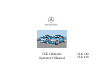
CLK Cabriolet Operator’s Manual CLK 320 CLK 430
Our company and staff congratulate you on the purchase of your new Mercedes-Benz. Your selection of our product is a demonstration of your trust in our company name. Further, it exemplifies your desire to own an automobile that will be as easy as possible to operate and provide years of service. Your Mercedes-Benz represents the efforts of many skilled engineers and craftsmen.
Introduction Product information Operator’s manual Where to find it Reporting Safety Defects 7 8 13 15 Instruments and controls Instruments and controls Center console Overhead control panel 18 20 21 Operation Vehicle keys Start lock-out General notes on the central locking system Central locking system Radio frequency and infrared remote control Locking and unlocking Choosing global or selective mode on remote control Opening the trunk Opening and closing windows from outside Panic button Mechanical ke
Operation Audio and telephone Power windows Interior lighting Entrance lamps, exit lamps in doors Sun visors Illuminated vanity mirrors Interior Storage compartments, armrest and cup holder Glove box Ashtray Lighter 125 143 146 146 147 147 148 148 The first 1 000 miles (1 500 km) Maintenance Catalytic converter Emission control Tele Aid Steering lock Starting and turning off the engine Automatic transmission 171 171 172 173 174 180 182 183 Travelling abroad Cruise control Brake assist system (BAS) Antil
Malfunction and indicator lamps in the center console 221 AIRBAG OFF indicator lamp 221 Roll bar warning lamp 221 Malfunction and warning messages in the multifunction display DISPLAY DEFECTIVE (engine control unit) DISPLAY DEFECTIVE (several systems) BATTERY/ALTERNATOR ABS-SYSTEM BRAKE ASSIST BRAKE LINING WEAR BRAKE FLUID PARKING BRAKE ENGINE FAN COOLANT (coolant level) COOLANT TEMP. (coolant temperature) LIGHTING SYSTEM LIGHT SENSOR STEER. WHEEL ADJUST. OIL TEMP. ENGINE OIL LEVEL ELEC. STABIL. PROG.
Headlamps, taillamps, turn signal lenses Wiper blade Seat belts Headliner Instrument cluster Steering wheel and gear selector lever Hard plastic trim items 294 294 294 294 294 295 295 Upholstery Ornamental moldings Paintwork, painted body components Light alloy wheels Soft top Wind screen Rubber weatherstrip 295 295 296 296 297 298 298 Technical data Spare parts service Warranty coverage Identification labels Layout of poly-V-belt drive Technical data Fuels, coolants, lubricants etc.
Product information Kindly observe the following in your own best interest: We recommend using Mercedes-Benz original parts as well as conversion parts and accessories explicitly approved by us for your vehicle model. We have tested these parts to determine their reliability, safety and their special suitability for Mercedes-Benz vehicles.
Introduction Operator’s manual This Operator’s Manual contains a great deal of useful information. We urge you to read it carefully and familiarize yourself with the vehicle before driving. For your own safety and longer service life of the vehicle, we urge you to follow the instructions and warnings contained in this manual. Ignoring them could result in damage to the vehicle or personal injury to you or others.
Important notice for California retail buyers of Mercedes-Benz automobiles Under California law you may be entitled to a replacement of your vehicle or a refund of the purchase price, if Mercedes-Benz USA, LLC or its authorized Mercedes-Benz Center fails to conform the vehicle to its express warranties after a reasonable number of repair attempts during the period of one year or 12 000 miles from original delivery of the vehicle.
Introduction Change of address or ownership If you change your address, be sure to send in the “Change of Address Notice” found in the Service and Warranty Information Booklet, or simply call the Mercedes-Benz Client Assistance Center (in the USA) at 1-800-FOR-MERCedes, or Customer Service (in Canada) at 1-800-387-0100. It is in your own interest that we can contact you should the need arise. If you sell your Mercedes, please leave all literature with the vehicle to make it available to the next operator.
Operating your vehicle outside the USA or Canada If you plan to operate your vehicle in foreign countries, please be aware that: • Service facilities or replacement parts may not be readily available, • unleaded gasoline for vehicles with catalytic converters may not be available; the use of leaded fuels will damage the catalysts, • gasoline may have a considerably lower octane rating, and improper fuel can cause engine damage.
Introduction We continuously strive to improve our product, and ask for your understanding that we reserve the right to make changes in design and equipment. Therefore, information, illustrations and descriptions in this Operator’s Manual might differ from your vehicle. Optional equipment is also described in this manual, including operating instructions wherever necessary.
Where to find it The Operator’s Manual is divided into eight sections: • Instruments and controls: An overview of all the controls that can be operated from the driver’s seat. • Operation: Information on the vehicle’s equipment and its operation. • Driving: Important information on driving. • Instrument cluster display: Displays and indicator lamps on the instrument cluster with brief instructions. • Practical hints: Assistance and instructions in the event of an emergency.
Introduction Problems with your vehicle If you should experience a problem with your vehicle, particularly one that you believe may affect its safe operation, we urge you to immediately contact your authorized Mercedes-Benz Center to have the problem diagnosed and corrected if required.
For the USA only: The following text is published as required of manufacturers under Title 49, Code of U.S. Federal Regulations, Part 575 pursuant to the “National Traffic and Motor Vehicle Safety Act of 1966”. Reporting Safety Defects If you believe that your vehicle has a defect which could cause a crash or could cause injury or death, you should immediately inform the National Highway Traffic Safety Administration (NHTSA) in addition to notifying Mercedes-Benz USA, LLC.
Instruments and controls Instruments and controls Center console Overhead control panel 18 20 21 17
Instruments and controls Operation Driving Instrument cluster display Practical hints Car care Technical data Index Instruments and controls Instruments and controls 18
For more detailed descriptions see Index on page 315. 13 Center air outlets, adjustable For adjustment of air outlets, refer to automatic climate control, see page 118.
Instruments and controls Operation Driving Instrument cluster display Practical hints Car care Technical data Index Instruments and controls Center console 1 Soft top switch, see page 158 2 ESP control switch, see page 209 3 Program mode selector switch, see page 190 4 Left power window switch (front), see page 143 5 Right power window switch (front), see page 143 1 6 Left power window switch (rear), see page 143 7 Trunk lid release switch, see page 41 3 ESP 2 8 Mirror adjustment switch, see
Overhead control panel 1 Tele Aid (emergency call system), see page 174 2 Interior lighting, see page 146 1 3 Hands-free microphone for Tele Aid, telephone and voice recognition system.
Operation Vehicle keys Start lock-out General notes on the central locking system Central locking system Radio frequency and infrared remote control Locking and unlocking Choosing global or selective mode on remote control Opening the trunk Opening and closing windows from outside Panic button Mechanical keys Doors 24 27 27 28 28 30 31 31 32 33 33 34 Central locking switch Automatic central locking Emergency unlocking in case of accident Trunk Trunk lid release switch Antitheft alarm system Tow-away alarm
Multifunction steering wheel, multifunction display Trip and main odometer, vehicle speed, FSS and engine oil level indicator Audio systems Telephone Navigation system Trip computer Malfunction message memory Individual settings Setting the audio volume Flexible service system (FSS) Engine oil level indicator Engine oil consumption Exterior lamp switch Night security illumination Headlamp cleaning system Combination switch Hazard warning flasher switch Automatic climate control Operation Audio and telephone
Instruments and controls Operation Driving Instrument cluster display Practical hints Car care Technical data Index Central locking system Vehicle keys Warning! Included with your vehicle are: When leaving the vehicle always remove the electronic key from the steering lock, and lock your vehicle. Do not leave children unattended in the vehicle, or with access to an unlocked vehicle. Unsupervised use of vehicle equipment may cause serious personal injury.
Electronic main key The mechanical key (2) can be removed by sliding it out of the remote control. To do so, move lock (3) in direction of arrow and slide the mechanical key (2) in direction of arrow (5 ). When using the mechanical key (2) for lock operations, it can be removed by sliding it out of the remote control. To do so, move locking tab (3) to the right and slide the mechanical key (2) in direction of arrow (4). P80.35-2031-26 The remote control transmitter is located in the electronic main key.
Instruments and controls Operation Driving Instrument cluster display Practical hints Car care Technical data Index Central locking system Electronic reserve key The electronic reserve key (1) works only in the steering lock. There are no batteries inside the electronic reserve key. The mechanical key (2) works only in the driver’s door, trunk, and storage compartment locks. To use the mechanical key (2), remove it from its electronic reserve key (1). Note: P80.
Start lock-out General notes on the central locking system Important! Removing the electronic key from the steering lock activates the start lock-out. The engine cannot be started. Inserting the electronic key in the steering lock deactivates the start lock-out. Note: In case the engine cannot be started (vehicle’s battery is in order), the system is not operational. Contact an authorized Mercedes-Benz Center or call 1-800-FORMERCedes (in the USA) or 1-800-387-0100 (in Canada).
Instruments and controls Operation Driving Instrument cluster display Practical hints Car care Technical data Index Central locking system Central locking system Radio frequency and infrared remote control The electronic main key has an integrated radio frequency and infrared remote control. Due to the extended operational range of the remote control, it could be possible to unintentionally lock or unlock the vehicle by pressing the transmit button.
6 7 P80.30-2081-26 6 Infrared receiver in driver’s door handle P80.
Instruments and controls Operation Driving Instrument cluster display Practical hints Car care Technical data Index Central locking system Locking and unlocking with remote control Unlocking: Press transmit button Œ. All turn signal lamps blink once to indicate that the vehicle is unlocked. The remote control can be programmed for two kinds of unlocking modes (see below): Selective unlocking mode – Press transmit button Œ once to unlock driver’s door and fuel filler flap.
Choosing global or selective mode on remote control Important! Press and hold transmit buttons ‹ and Œ simultaneously for approx. 6 seconds to reprogram the remote control. Battery check lamp will blink two times indicating the completed mode change. Do not place remote control in trunk since trunk is locked when the lid is closed if the vehicle is centrally locked. Note: Opening the trunk Press transmit button Š until trunk lid is released.
Instruments and controls Operation Driving Instrument cluster display Practical hints Car care Technical data Index Central locking system Opening and closing windows from outside Note: Aim transmitter eye of remote control at a door receiver. The windows begin to open after approx. 1 second.
Panic button Note: For operation in the USA only: This device complies with Part 15, Subpart C, Section 209 of the FCC Rules. Operation is subject to the following two conditions: (1) This device may not cause harmful interference, and (2) this device must accept any interference received, including interference that may cause undesired operation. WARNING: Changes or modification not expressly approved by party responsible for compliance could void the user’s authority to operate the equipment. P80.
Instruments and controls Operation Driving Instrument cluster display Practical hints Car care Technical data Index Central locking system Doors 1 3 2 1 1 Opening – pull handle Important! 2 Unlocking driver’s door The mechanical key does not operate the central locking system or antitheft alarm system. 3 Locking driver’s door 4 Individual door from inside: • Push lock button down to lock. • Pull inside door handle to unlock.
If the vehicle has previously been locked from the outside, opening a door from the inside will trigger the alarm. When opening a door while the central locking system is in the: • selective unlocking mode, only that individual door is unlocked. The remaining door, the trunk and fuel filler flap remain locked, • global unlocking mode, both doors, the trunk and fuel filler flap are unlocked. Notes: To lock, push down lock button and turn mechanical key in driver’s door lock to position 3.
Instruments and controls Operation Driving Instrument cluster display Practical hints Car care Technical data Index Central locking system Central locking switch If the vehicle was previously locked with the central locking switch, while in the global remote control mode, the complete vehicle is unlocked when a door is opened from the inside. Notes: If the vehicle was previously locked with the remote control, the doors and trunk cannot be unlocked with the central locking switch.
Automatic central locking Notes: The central locking switch also operates the automatic central locking. If doors are unlocked with the central locking switch after activating the automatic central locking, and neither door is opened, then the doors remain unlocked even at vehicle speeds of approx. 9 mph (15 km/h) or more. With the automatic central locking system activated, the doors and trunk are locked at vehicle speeds of approx. 9 mph (15 km/h) or more. The fuel filler flap remains unlocked.
Instruments and controls Operation Driving Instrument cluster display Practical hints Car care Technical data Index Central locking system Important! Emergency unlocking in case of accident When towing the vehicle, or with the vehicle on a dynamometer test stand, please, note the following: The doors unlock automatically a short time after a strong deceleration is detected, such as in a collision (this is intended to aid rescue and exit).
Trunk When the trunk is separately locked, it remains locked when centrally unlocking the vehicle. To deny any unauthorized person access to the trunk, lock it separately with the mechanical key. Leave only the electronic main key less its mechanical key with the vehicle. Notes: The mechanical key does not operate the central locking system or antitheft alarm system. The trunk can also be opened by using the electronic main key. Press Š button.
Notes: In case of a malfunction in the central locking system the trunk can be unlocked individually. To unlock and open the trunk lid, turn mechanical key to position 1, hold and push to open. If the fuel filler flap cannot be opened, see page 298. 1 Important! Do not place mechanical key inside trunk, since trunk is locked when the lid is closed if the vehicle has been previously centrally locked.
Instruments and controls Operation Driving Instrument cluster display Practical hints Car care Technical data Index Central locking system Trunk lid release switch A minimum height clearance of 5.9 ft. (1.8 m) is required to open the trunk lid. To open the trunk, the vehicle must be at standstill. Pull up on switch until trunk lid is open. The indicator lamp in the switch remains on with trunk lid open.
Instruments and controls Operation Driving Instrument cluster display Practical hints Car care Technical data Index Antitheft alarm system Antitheft alarm system The antitheft alarm is automatically armed or disarmed with the remote control by locking or unlocking the vehicle. The antitheft alarm is armed within approx. 10 seconds after locking the vehicle. A blinking lamp (1) indicates that the alarm is armed.
The alarm will last approximately 3 minutes in form of flashing exterior lamps. At the same time an alarm will sound for 30 seconds. The alarm will stay on even if the activating element (a door, for example) is immediately closed. The antitheft alarm system is switched off automatically if the vehicle is unlocked with the electronic main key. If the alarm stays on for more than 20 seconds, an emergency call is initiated automatically. See Tele Aid on page 182.
Instruments and controls Operation Driving Instrument cluster display Practical hints Car care Technical data Index Tow-away alarm Tow-away alarm The alarm will last approximately 3 minutes in form of flashing exterior lamps. At the same time an alarm will sound for 30 seconds. The alarm will stay on even if the vehicle is immediately lowered. The tow-away alarm system is switched off automatically if the vehicle is unlocked with the electronic main key.
Power seats, front Warning! Warning! Do not adjust the driver’s seat while driving. Adjusting the seat while driving could cause the driver to lose control of the vehicle. When leaving the vehicle always remove the electronic key from the steering lock, and lock your vehicle. Never ride in a moving vehicle with the backrest reclined. Sitting in an excessively reclined position can be dangerous. You could slide under the seat belt in a collision.
Instruments and controls Operation Instrument cluster display Driving Practical hints Car care Technical data Index Seats safely. The position should be as far rearward as possible, consistent with ability to properly operate controls. 5 4 8 7 2 2 1 3 The slide switches are located in each door. We recommend to adjust the power seat in the following order: 1 Seat, up/down Press the switch (up/down direction) until comfortable seating position with still sufficient headroom is reached.
Synchronizing power seats and head restraints Memory storing and recalling If the power supply was interrupted (battery disconnected or empty), the power seats and head restraints are no longer adjusted automatically. To resynchronize the adjustment feature, turn electronic key in steering lock to position 2, move the seat completely forward and the head restraint fully down, and hold respective buttons for approx. 2 seconds. Caution ! Do not remove head restrains except when mounting seat covers.
Instruments and controls Operation Driving Instrument cluster display Practical hints Car care Technical data Index Seats Storing Three sets of seat/head restraint and exterior rear view mirror positions may be programmed into memory. After the seat/head restraint and exterior rear view mirrors are positioned, push memory button (6), release, and within 3 seconds push position button “1”.
Important! Warning! Prior to operating the vehicle, the driver should adjust the seat height for proper vision as well as fore/aft placement and backrest angle to insure adequate control, reach, operation, and comfort. The head restraint should also be adjusted for proper height. See also airbag section on page 66 for proper seat positioning.
Instruments and controls Operation Driving Instrument cluster display Practical hints Car care Technical data Index Seats Front head restraints Warning! For your protection, drive only with properly positioned head restraints. Adjust head restraint to support the back of the head approximately at ear level. Do not drive the vehicle without the seat head restraints. Head restraints are intended to help reduce injuries during an accident.
Roll bar and head restraints, rear Warning! The rear head restraints are integrated in the roll bar. Raising or lowering of the roll bar could injure rear seated occupants. The roll bar will be automatically raised in an accident or in a potentially dangerous driving situation. A ratchet noise can be heard when the roll bar is automatically raised. Before operating the roll bar switch make sure that the roll bar’s path is clear and no persons due to inattention are injured by the moving roll bar.
Switch for roll bar and head restraints, rear With the engine running and the roll bar lowered, the warning lamp in the roll bar switch will blink for approx. 15 seconds. The blinking is reminding you to raise the roll bar if the rear passenger seats are occupied. See also page 233 for roll bar warning lamp. 1 Important! 2 P91.59-2001-26 The switch is located in the center console. Turn electronic key in steering lock to position 2.
Instruments and controls Operation Driving Instrument cluster display Practical hints Car care Technical data Index Seats Backrest Notes: The automatic seat slide is provided with a safety feature. The automatic process is interrupted, if the backrest of the sliding seat is pushed against an occupant or object. The seat will slide forward, stop, and make 3 attempts sliding backward. To halt the automatic process, activate the power seat switch. Investigate and correct the cause of interruption.
Multicontour seat (optional) We recommend to adjust the multicontour seat in the following order: 1 Seat cushion depth Slide the switch fore or aft until your legs are supported comfortably. 4 2 Backrest bottom 3 Backrest center 1 2 3 4 Side bolster adjustment Adjust the side bolster to provide good lateral support. P91.25-2063-26 Some models may be equipped with multicontour seats.
Instruments and controls Operation Driving Instrument cluster display Practical hints Car care Technical data Index Seats Heated seats, front (optional) Press switch to turn on seat heater: 1 Normal seat heating mode. One indicator lamp in the switch lights up. 1 2 Rapid seat heating mode. Both indicator lamps in the switch light up. After approximately 5 minutes in the rapid seat heating mode, the seat heater automatically switches to normal operation and only one indicator lamp will stay on.
Notes: When in operation, the seat heater consumes a large amount of electrical power. It is not advisable to use the seat heater longer than necessary. The seat heaters may automatically switch off if too many power consumers are switched on at the same time, or if the battery charge is low. When this occurs, the indicator lamp in the switch will blink (both indicator lamps blink during rapid seat heating mode). The seat heaters will switch on again automatically as soon as sufficient voltage is available.
Instruments and controls Operation Driving Instrument cluster display Practical hints Car care Technical data Index Restraint systems Seat belts and integrated restraint system Warning! Your vehicle is equipped with seat belts for all seats, emergency tensioning retractors for the front seat belts, dual front airbags, door mounted side impact airbags and knee bolsters for driver and front passenger. Their protective functions are designed to complement one another.
Warning! Warning! Never ride in a moving vehicle with the backrest reclined. Sitting in an excessively reclined position can be dangerous. You could slide under the seat belt in a collision. If you slide under it, the belt would apply force at the abdomen or neck. That could cause serious or even fatal injuries. The backrest and seat belt provide the best restraint when the wearer is in an upright position and the belt is properly positioned on the body.
Instruments and controls Operation Driving Instrument cluster display Practical hints Car care Technical data Index Restraint systems Fastening of seat belts Push latch plate (1) into buckle (2) until it clicks. Do not twist the belt. A twisted seat belt may cause injury. To help avoid severe or fatal injuries, the lap belt must be positioned as low as possible on your hips and not across the abdomen. 1 Warning! Always fasten your seat belt before driving off.
Unfastening of seat belts 1 2 P91.40-2102-26 Tighten the lap portion to a snug fit by pulling shoulder portion up. The shoulder portion of the seat belt must be pulled snug and checked for snugness immediately after engaging it. Adjust seat belt so that shoulder portion is located as close as possible to the middle of your shoulder (it should not touch the neck). 3 Push the release button (3) in the belt buckle (2). Allow the retractor to completely rewind the seat belt by guiding the latch plate (1).
Instruments and controls Operation Driving Instrument cluster display Practical hints Car care Technical data Index Restraint systems Caution! For safety reasons, avoid adjusting the seat or backrest into positions which could affect the correct seat belt position. Warning! USE SEAT BELTS PROPERLY. • Seat belts can only work when used properly. Never wear seat belts in any other way than as described in this section, as that could result in serious injuries in case of an accident.
• Pregnant women should also use a lapshoulder belt. The lap belt portion should be positioned as low as possible on the hips to avoid any possible pressure on the abdomen. • Never place your feet on the instrument panel or on the seat. Always keep both feet on the floor in front of the seat. According to accident statistics, children are safer when properly restrained in the rear seating positions than in the front seating positions.
Instruments and controls Operation Driving Instrument cluster display Practical hints Car care Technical data Index Restraint systems BabySmartTM airbag deactivation system TM Special BabySmart compatible child seats, designed for use with the Mercedes-Benz system and available at any authorized Mercedes-Benz Center are required for use with the BabySmartTM airbag deactivation system. With the special child seat properly installed, the passenger front airbag will not deploy.
Supplemental restraint system (SRS) Emergency tensioning retractor (ETR) Airbags are intended as a supplement to seat belts. Airbags alone cannot protect as well as airbags plus seat belts in impacts for which the airbags were designed to operate, and do not afford any protection whatsoever in crashes for which the airbags are not designed to deploy. The seat belts for the front seats are equipped with emergency tensioning retractors.
Instruments and controls Operation Driving Instrument cluster display Practical hints Car care Technical data Index Restraint systems Airbags 2 SRS AIRBAG AIRBAG 1 1 Driver airbag The driver airbag is located in the steering wheel hub. 2 Front passenger airbag The passenger front airbag is located in the dashboard ahead of the front passenger.
mounted side impact airbags can provide increased protection to belted front passengers on the impacted side of the vehicle in side impacts exceeding its preset threshold. Important! 3 P91.60-2122-26 3 Side impact airbag The side impact airbags are located in the doors. The most effective occupant restraint system yet developed for use in production vehicles is the seat belt. In some cases, however, the protective effect of a seat belt can be further enhanced by an airbag.
Instruments and controls Operation Driving Instrument cluster display Practical hints Car care Technical data Index Restraint systems In the operational mode, after the indicator lamp has gone out following the initial check, interruptions or short circuits in the airbag ignition circuit and in the driver and front passenger seat belt buckle harnesses, and low voltage in the entire system are detected and indicated.
Important! Airbags are designed to activate only in certain frontal (front airbags) impacts, or side (side impact airbags) impacts which exceed preset thresholds. Only during these types of impacts, if of sufficient severity to meet the deployment thresholds, will they provide their supplemental protection. The driver and passenger should always wear their seat belts, otherwise it is not possible for the airbags to provide their intended supplemental protection.
Instruments and controls Operation Driving Instrument cluster display Practical hints Car care Technical data Index Restraint systems Your vehicle was originally equipped with airbags which are designed to activate in certain impacts exceeding a preset threshold to reduce the potential and severity of injury.
• Children 12 years old and under must never ride in the front seat, except in a Mercedes-Benz authorized BabySmart TM compatible child seat, which operates with the BabySmartTM system installed in the vehicle to deactivate the passenger front airbag when it is properly installed. Otherwise they will be struck by the airbag when it inflates in a crash. If this happens, serious or fatal injury can result. Failure to follow these instructions can result in severe or fatal injuries to you or other occupants.
• In addition, through improper work there is the risk of rendering the “SRS” inoperative or causing unintended airbag deployment. Work on the “SRS” must therefore only be performed by an authorized Mercedes-Benz Center. • For your protection and the protection of others, when scrapping the airbag unit or emergency tensioning retractor, our safety instructions must be followed. These instructions are available at your authorized Mercedes-Benz Center.
Instruments and controls Operation Driving Instrument cluster display Practical hints Car care Technical data Index Restraint systems Important! The use of infant or child restraints is required by law in all 50 states and all Canadian provinces. Infants and small children should be seated in an appropriate infant or child restraint system properly secured by a lap-shoulder belt, and that complies with U.S. Federal Motor Vehicle Safety Standard 213 and Canadian Motor Vehicle Safety Standard 213.
Children too big for child restraint systems must ride in back seats using regular seat belts. Position shoulder belt across chest and shoulder, not face or neck. A booster seat may be necessary to achieve proper belt positioning for children from 41 lbs. to the point where a lap/shoulder belt fits properly without one. When the child restraint is not in use, remove it from the vehicle or secure it with the seat belt to prevent the child restraint from becoming a projectile in the event of an accident.
Instruments and controls Operation Instrument cluster display Driving Practical hints Car care Technical data Index Adjusting telescoping steering column Adjusting telescoping steering column Unlocking: Pull handle (1) out to its stop. The indicator lamp, located in the instrument cluster, comes on. Adjusting: To lengthen or shorten the steering column, pull out or push in steering wheel. Locking: Push handle (1) in until it engages. The indicator lamp, located in the instrument cluster, goes out.
Inside rear view mirror Note: Manually adjust the mirror. The automatic antiglare function does not react, if incoming light is not aimed directly at sensors in the mirror. Use your inside mirror to determine the size and distance of objects seen in the passenger side convex mirror. Antiglare night position With the electronic key in steering lock position 2, the mirror reflection brightness responds to changes in light sensitivity.
Instruments and controls Operation Driving Instrument cluster display Practical hints Car care Technical data Index Rear view mirrors Exterior rear view mirrors With the electronic key in steering lock position 2, the driver’s side mirror reflection brightness responds to changes in light sensitivity. With gear selector lever in position “R”, or with the interior lamp switched on, the driver’s side mirror brightness does not respond to changes in light sensitivity.
Warning! In the case of an accident liquid electrolyte may escape the mirror housing when the mirror glass breaks. Electrolyte has an irritating effect. Do not allow the liquid come into contact with eyes, skin, clothing, or respiratory system. In cases it does, immediately flush affected area with water, and seek medical help if necessary. Important! Electrolyte drops coming into contact with the vehicle paint finish can only be completely removed while in their liquid state, by applying plenty of water.
Storing mirror positions in memory Parking position The exterior rear view mirror positions are stored in memory with the seat/head restraint position and can be recalled when necessary, see page 47. The passenger-side exterior mirror can be adjusted and programmed to assist the driver during parking maneuvers (e.g. to observe the curb or other objects close to the vehicle).
Instruments and controls Operation Driving Instrument cluster display Practical hints Car care Technical data Index Rear view mirrors At speeds above approx. 6 mph (10 km/h), upon shifting gear selector lever from “R” Reverse, or upon pressing the driver’s side mirror button, the passenger-side mirror will return to its previous position. Readjust the mirror as desired. One passenger-side mirror position can be stored in memory. To do so: 4.
Instrument cluster 80
1 Push buttons V and W for intensity of instrument lamps, see page 83 2 Push button J for resetting trip odometer, see page 85, or multifunction indicator see page 85 3 Coolant temperature gauge, see page 84 4 Fuel gauge with reserve and fuel cap placement warning lamp, see page 218 5 Outside temperature indicator, see page 84 6 Left turn signal indicator lamp, see combination switch on page 115 7 ESP warning lamp, see page 219 8 Speedometer 9 Trip odometer, see page 85 10 Main odometer 11 Multifunction in
Instruments and controls Operation Driving Instrument cluster display Practical hints Car care Technical data Index Instrument cluster Indicator lamps in the instrument cluster Telescoping steering column not locked, see page 220 High beam ABS malfunction, see page 219 SRS ABS BRAKE Brake fluid low (except Canada), Parking brake engaged, see page 226 Brake fluid low (Canada only), Parking brake engaged, see page 226 BAS ESP BAS malfunction, see page 204 ESP malfunction, see page 208 ESP.
Activating instrument cluster display Instrument lamps The instrument cluster is activated by: • Opening the door. • Pressing button J, V or W on the instrument cluster. • Turning the electronic key in steering lock to position 1 or 2. • Switching on the exterior lamps. Display illumination The display for temperature, odometer, multifunction indicator, FSS indicator and clock is illuminated briefly when opening the driver’s door.
Instruments and controls Operation Driving Instrument cluster display Practical hints Car care Technical data Index Instrument cluster Coolant temperature gauge (3) Outside temperature indicator (5) During severe operating conditions and stop-and-go city traffic, the coolant temperature may rise close to the red marking. The temperature sensor is located in the front bumper area. Due to its location, the sensor can be affected by road or engine heat during idling or slow driving.
Trip odometer (9) Tachometer (13) To reset to “0” miles/km: The red marking on tachometer denotes excessive engine speed. Activate the instrument cluster if it is not already activated by pressing the J button on the instrument cluster. Press button è or ÿ on the multifunction steering wheel repeatedly until the trip odometer appears if it is not displayed. See page 92. Avoid this engine speed, as it may result in serious engine damage that is not covered by the Mercedes-Benz Limited Warranty.
Instruments and controls Operation Driving Instrument cluster display Practical hints Car care Technical data Index Multifunction steering wheel, multifunction display Multifunction steering wheel, multifunction display 86
Depending on your vehicle’s equipment, you may use the buttons on the multifunction steering wheel to call up, control and set the following systems in the multifunction display: 1 Trip odometer and main odometer, see page 90 Flexible service system (FSS), see page 107 Engine oil level indicator, see page 110 Press the è or ÿ button repeatedly until the required system is displayed. Pressing the è button advances the display to the next system.
Instruments and controls Operation Instrument cluster display Driving Practical hints Car care Technical data Index Multifunction steering wheel, multifunction display Turn the electronic key in steering look to position 1 or 2.
Press the è or ÿ button repeatedly until the required system is displayed. Pressing the è button advances the display to the next system. Pressing the ÿ button returns the display to the previous system. You may call up additional displays in some systems by pressing the j or k button. Note: The displays in the multifunction display can be set to German, English, French, Italian or Spanish language. See the “TEXT” individual setting on page 104 for instructions on changing the language setting.
Instruments and controls Operation Driving Instrument cluster display Practical hints Car care Technical data Index Multifunction steering wheel, multifunction display Trip and main odometer, vehicle speed, FSS and engine oil level indicator 1 Trip odometer and main odometer See page 85 for instructions on resetting the trip odometer. 2 FSS (Flexible service system), see page 107. 3 Engine oil level indicator, see page 110 .
Audio systems 1 Audio system is switched off. Radio 2 The radio is switched on. 3 Wave band setting and memory location number, where appropriate. 4 Station frequency. 5 This only appears when “MEMORY” rather than “FREQUENCY” has been selected in the individual settings. See page 104 . The radio must be switched on. Press the è or ÿ button repeatedly until display (2) appears. Press button j or k repeatedly until the required station or frequency is displayed.
Instruments and controls Operation Driving Instrument cluster display Practical hints Car care Technical data Index Multifunction steering wheel, multifunction display CD player (optional) 1 Audio system is switched off. 2 The CD player is switched on. 3 The number of the CD currently playing is displayed if you are using a CD changer. 4 Track number. The radio must be switched on. The CD player must be switched on. Press the è or ÿ button repeatedly until display (2) appears.
Cassette player 1 Audio system is switched off. 2 The cassette player is switched on. 3 Side being played. The radio must be switched on. The cassette player must be switched on. Press the è or ÿ button repeatedly until display (2) appears. Pressing the j button fast forwards on to the next track. Pressing the k button rewinds the cassette to the beginning of the current track. Pressing the è or ÿ button displays the next or previous system.
Instruments and controls Operation Driving Instrument cluster display Practical hints Car care Technical data Index Multifunction steering wheel, multifunction display Telephone 1 The telephone is switched off. Telephone book 2 The vehicle is currently outside the transmitter or receiver range. 3 The telephone is ready for use. 4 Name selected from the telephone book. 5 Number for the name selected. Dialing commences. 6 Dialing is completed. The name is displayed.
The telephone must be switched on. Press the è or ÿ button repeatedly until the display (3) appears. Refer to the separate telephone instruction manual. Pressing j or k “browses” alphabetically forwards or backwards through the telephone book, providing it was previously downloaded. See telephone operator’s manual for details concerning downloading. Pressing button j or k for longer than a second “browses” rapidly through the telephone book. The name selected appears in the display.
Instruments and controls Operation Driving Instrument cluster display Practical hints Car care Technical data Index Multifunction steering wheel, multifunction display Redialing 1 The telephone is ready for use. 2 Number or name stored in the redial memory. 3 Number in the redial memory – redialing has commenced. 4 Dialing is completed and the name stored in the telephone book is displayed or the number dialed will remain displayed if no name has been stored.
The telephone must be switched on. Press the è or ÿ button repeatedly until the display (1) appears. Pressing the í button activates the redial memory and the most recently dialed number is displayed. Pressing the j or k button “browses” forwards or backwards through the redial memory. The number selected appears in the display. Note: Press the ì button if you do not wish to make a call. Press the í button when the required number or name appears in the display (2). The telephone number (3) is dialed.
Instruments and controls Operation Driving Instrument cluster display Practical hints Car care Technical data Index Multifunction steering wheel, multifunction display Incoming call 1 “CALL” — you are being called Press the í button to answer the call. Press the ì button to hang up or if you do not wish to answer the incoming call. The telephone must be switched on.
Navigation system (optional) 1 The navigation system is switched off. 2 The navigation system is switched on but no destination has been specified. 3 The navigation system is switched on and destination guidance is active. Press the è or ÿ button repeatedly until the required system is displayed. See the separate COMAND (Cockpit Management and Data System) operator’s manual for notes on the navigation system. Pressing the è or ÿ button displays the next or previous system. P54.
Instruments and controls Operation Driving Instrument cluster display Practical hints Car care Technical data Index Multifunction steering wheel, multifunction display Trip computer 1 “AFTER START” – trip odometer records distance from first engine start after more than five hours of electronic key not being in steering lock position 2 2 “AFTER RESET” – trip odometer records distance from first engine start until reset 3 Estimated driving range remaining and fuel tank contents 4 Distance covered “A
Press the button è or ÿ repeatedly until the display (1) appears. To reset the “AFTER START” (1) or “AFTER RESET” (2) odometer memory at any time: Press the j or k button until the display for trip odometer memory “AFTER START” (1) and “AFTER RESET” (2), or the display (3) for estimated driving range remaining and fuel tank contents appears. Pressing the è or ÿ button displays the next or previous system.
Instruments and controls Operation Driving Instrument cluster display Practical hints Car care Technical data Index Multifunction steering wheel, multifunction display Malfunction message memory 1 There are no messages stored in the system 2 Number of messages stored in the system Press the è or ÿ button repeatedly until the malfunction message memory (1 or 2) is displayed. Press the j or k button if display (2) appears. The stored malfunction messages will now be displayed in order.
Should any malfunctions be stored while driving, they will reappear in the display (2) when the electronic key is in steering lock position 0 or removed from the steering lock. Specific malfunctions can be recalled by pressing button J. Each malfunction or warning message must be acknowledged by pressing button J. Once all messages are cancelled, the odometer display should reappear. Pressing the J button in the instrument cluster immediately switches to the next malfunction message.
Instruments and controls Operation Driving Instrument cluster display Practical hints Car care Technical data Index Multifunction steering wheel, multifunction display Individual settings 104
1 Preliminary display of the individual settings 7 “STATION SEARCH USING” – radio adjustment 2 “SET TIME HOURS” (Only vehicles without COMAND) “FREQUENCY” – use the j or k button to select a frequency 3 “SET TIME MINUTES” (Only vehicles without COMAND) “MEMORY” – use the j or k button to select a stored station (preset memory) 4 “12/24 HOURS” – the unit set is displayed in the instrument cluster (Only vehicles without COMAND) 5 “TEMP.
Instruments and controls Operation Driving Instrument cluster display Practical hints Car care Technical data Index Multifunction steering wheel, multifunction display Press the è or ÿ button repeatedly until the individual setting preliminary display (1) appear. Press the j or k button until the required setting menu (2 to 8) is displayed. Pressing the æ or ç button sets the time in setting menus (2, 3) and controls the selection marker in setting menus (4 to 8).
Flexible service system (FSS) (service indicator) 60 100 80 40 80 120 140 The message is displayed for approx. 10 seconds when turning the electronic key in steering lock to position 2, or while driving when reaching the service warning threshold.
Instruments and controls Operation Driving Instrument cluster display Practical hints Car care Technical data Index Flexible service system The service indicator disappears automatically after 30 seconds or if button J on the instrument cluster is pressed. Calling up service indicator manually: Turn the electronic key in steering lock to position 1. Call up the trip odometer and main odometer, by pressing button è or ÿ on the multifunction steering wheel until the display appears. See page 90.
Following a completed A or B service the Mercedes-Benz Center sets the counter mileage to 10 000 miles (Canada: 15 000 km) and 365 days. The multifunction display will show the question: “DO YOU WANT TO RESET SERVICE INTERVAL? – CONFIRM BY PRESSING R” The counter can also be set by any individual. To do so: Press button J on the instrument cluster again, and hold until a signal sounds. The message “SERVICE INTERVAL HAS BEEN RESET” appears in the multifunction display.
Instruments and controls Operation Driving Instrument cluster display Practical hints Car care Technical data Index Engine oil level indicator Engine oil level indicator Turn the electronic key in steering lock to position 2. To call up the trip odometer and main odometer, press button è or ÿ on the multifunction steering wheel until the display appears. See page 90 . Press button j or k on the multifunction steering wheel repeatedly until the “MEASUREMENT CORRECT – ONLY IF VEH.
One of the following messages will subsequently appear on the indicator: “ENGINE OIL LEVEL – O.K.” No oil needs to be added. “ENGINE OIL LEVEL – ADD 1.0 QUART” (Canada: 1.0 L) “ENGINE OIL LEVEL – ADD 1.5 QUART” (Canada: 1.5 L) “ENGINE OIL LEVEL – ADD 2.0 QUART” (Canada: 2.0 L) See page 246 for instructions on adding engine oil. “ENGINE OIL LEVEL – REDUCE OIL LEVEL” Do not overfill the engine. Excessive oil must be siphoned or drained off.
Instruments and controls Operation Driving Instrument cluster display Practical hints Car care Technical data Index Exterior lamp switch Exterior lamp switch B Parking lamps plus low beam or high beam headlamps (combination switch pushed forward) ˆ Standing lamps, right (turn left one stop) ‚ Standing lamps, left (turn left two stops) … Front fog lamps (pull out one stop) with parking lamps and/or low beam headlamps on. Green indicator lamp in lamp switch comes on.
Notes: Daytime running lamps (Canada only) With the electronic key removed and the driver’s door open, a warning sounds and the message “SWITCH OFF LIGHTS” in the multifunction indicator appears if the vehicle’s exterior lamps (except standing lamps) are not switched off. When the engine is running and the selector lever is in a driving position, the low beam headlamps (includes parking lamps, side marker lamps, taillamps and license plate lamps) are automatically switched on.
Instruments and controls Operation Driving Instrument cluster display Practical hints Car care Technical data Index Headlamp cleaning system Headlamp cleaning system (optional) The switch is located in the center console. The headlamp washer can be activated with the electronic key in steering lock position 2. Briefly press symbol side of switch. P82.
Combination switch 3 High beam flasher (high beam available independent of exterior lamp switch position) 4 Turn signals, right 5 Turn signals, left 4 4 To signal minor directional changes, such as changing lanes on a highway, move combination switch to the point of resistance only and hold it there. 2 To operate the turn signals continuously, move the combination switch past the point of resistance (up or down).
Instruments and controls Operation Instrument cluster display Driving Practical hints Car care Technical data Index Combination switch 7 0 Wiper off I Intermittent wiping (optional rain sensor: One initial wipe, pauses between wipes are automatically controlled by a rain sensor monitoring the wetness of the windshield.) Notes: 6 P54.25-2033-26 6 Control for windshield wiper/washer system: Push briefly for single wipe without adding washer fluid (use only when windshield is wet).
Windshield wiper smears Hazard warning flasher switch If the windshield wiper smears the windshield, even during rain, activate the washer system as often as necessary. The fluid in the washer reservoir should be mixed in the correct ratio, see page 259. Blocked windshield wiper If the windshield wiper becomes blocked (for example, due to snow), switch off the wiper. For safety reasons before removing ice or snow, remove electronic key from steering lock. Remove blockage.
Instruments and controls Operation Instrument cluster display Driving Practical hints Technical data Car care Index Automatic climate control Automatic climate control 3 3 4 1 2 65 DOLBY-STERE O z Mercedes-Ben * * P83.
1 Air volume control for center air outlets, turn wheel up to open. 2 Air volume control for side air outlet. To open air outlets: Turn wheel to position i. 3 Center air outlet, adjustable The temperature selector should be left at the desired temperature setting. The temperature selected is reached as quickly as possible. The system will not heat or cool any quicker by setting a higher or lower temperature.
Instruments and controls Operation Driving Instrument cluster display Practical hints Car care Technical data Index Automatic climate control P Defrost Display and controls O Air recirculation F Rear window defroster b Air distribution, manual S Economy mode ï Air volume, manual T Residual engine heat utilization 0 MAX Basic setting - automatic mode Press left and right U button for automatic mode. Press the desired button to activate, indicator lamp is on while activated.
Economy Defrosting The function of this setting corresponds to the automatic mode. However, because the air conditioning compressor will not engage (fuel savings), it is not possible to air condition in this setting. Turn wheels (2) to position i to open left and right side air outlets (4). Adjust side air outlets upward. Press S button to activate. Press S button once again to return to previous setting. Special settings (use only for short duration) Press P button.
Instruments and controls Operation Driving Instrument cluster display Practical hints Car care Technical data Index Automatic climate control Rear window defroster Turn electronic key in steering lock to position 2. To select, press F button. Air distribution T To cancel, press F button again. Press b button for each side repeatedly until the requested symbol is displayed. Notes: Press U button to return to automatic mode.
Air recirculation Residual engine heat utilization This mode can be selected to temporarily reduce the entry of annoying odors or dust into the vehicle’s interior. With the engine switched off, it is possible to continue heating the interior for a short while. Outside air is not supplied to the vehicle’s interior. To select, press O button. Air volume and distribution are controlled automatically. To select: To cancel, press O button again.
Instruments and controls Operation Driving Instrument cluster display Practical hints Car care Technical data Index Automatic climate control Dust filter Important! Nearly all dust particles and pollen are filtered out before outside air enters the passenger compartment through the air distribution system. This vehicle is equipped with an air conditioner system that uses R–134a (HFC: hydrofluorocarbon) as a refrigerant.
Operating safety Audio and telephone, operation These instructions are intended to help you become acquainted with your Mercedes-Benz vehicle radio. They contain useful tips and a detailed description of the user functions. Warning! In order to avoid distraction which could lead to an accident, system settings should be entered with the vehicle at standstill and systems should be operated by the driver only when traffic conditions permit.
Instruments and controls Operation Driving Instrument cluster display Practical hints Car care Technical data Index Audio system Operating and display elements 1 On/off, volume, see page 129 2 Telephone mode selector, see page 140 3 Seek, see page 131, 134 and 138 4 Radio mode selector, see page 131 5 Tune, see page 131 and 132 Fast forward/reverse, see page 139 6 CD mode selector, see page 133 7 Display panel The cassette slot is located behind the display panel.
10 Soft keys for radio band selection, see page 131 tone controls, see page 129 scan, see page 132 Tape eject, see page 134 Tape track select, see page 134 Dolby, see page 135 CD Random/repeat, see page 139 11 Tape mode selector, see page 133 Anti-theft system If the power supply to the radio has been interrupted, “CODE” will appear on the display when it is next switched on. The radio will only work after the five-digit code has been entered using the buttons on the right-hand control panel.
Instruments and controls Operation Driving Instrument cluster display Practical hints Car care Technical data Index Audio system Entering the code number Button and soft key operation Switch on the radio. “CODE” will appear on the display. Using the buttons on the alpha-numeric keypad, enter the five digit code. Confirm by pressing the “OK” key.
Operation Audio functions Switching on and off Press the control knob . The radio is switched off when the ignition key is turned to position 0 or removed from the ignition. The radio is switched on again when the ignition key is turned to position 1 or 2. The AUD key is used to select the BASS, TREBLE and BALANCE functions. Settings for bass and treble are stored separately for the cassette and CD modes. Tone level settings are identified by the vertical bars.
Instruments and controls Operation Driving Instrument cluster display Practical hints Car care Technical data Index Audio system Fader1 Centering all audio functions Press the AUD key repeatedly until “FADER” appears on the display. Press the “R” key to move the sound to the rear speakers or the “F” key to move the sound to the front speakers. Push and hold down the “AUD” key.
Radio mode Manual tuning Press either the or button. Step-by-step tuning in ascending or descending order of frequency will take place. Selecting radio mode Press button. Selecting the band Press the key located below the desired band. The band selected is shown in the top line of the display. Frequency ranges: The first three tuning steps will take place without muting. The radio will then be muted and high-speed tuning will take place until the button is released.
Instruments and controls Operation Driving Instrument cluster display Practical hints Car care Technical data Index Audio system Scan tuning Storing stations Press the SC key. Each strong receivable station on the band selected will be tuned in for 8 seconds. The first scan will tune only the stations with a high signal strength. The second scan will tune every receivable station. By pressing either the , , or buttons, or the “SC” key the scan mode can be cancelled.
Cassette mode Important! Note: If the display is in the down position for more than 20 seconds, 2 successive beeps will be heard. This will continue at 5 second intervals until the display is returned to its normal position. Vehicles equipped with the COMAND system do not come with a factory installed cassette mechanism.
Instruments and controls Operation Driving Instrument cluster display Practical hints Car care Technical data Index Audio system Cassette eject Track search forwards/backwards Press the eject (EJ) key. The display will fold down and the cassette will be ejected. Remove the cassette, then fold the display back up manually. The radio will switch back to radio mode automatically. Press the button.
Fast forward/reverse Scanning Press the button. “FORWARD” will appear on the display and fast forward will start. Press the button. “REWIND” will appear on the display and fast reverse will start. Fast forward/reverse is stopped by pressing the same button again, or it will stop automatically at the beginning or the end of the tape. The track will automatically change at the end or beginning of the tape and play will begin. Press the “SC” key.
CD mode Replace the CD in its container after use. Protect CDs from heat and direct sunlight. General notes on CD mode Should excessive temperatures occur while in CD mode, “TEMP HIGH” will appear in the display and muting will take place. The unit will then switch back to radio mode until the temperature has decreased to a safe operating level. Should temperatures occur while in CD mode which are too low, “TEMP LOW” will be displayed, but the CD will play.
Instruments and controls Operation Driving Instrument cluster display Practical hints Car care Technical data Index Audio system Loading/emptying the CD magazine CD changer installed Slide the changer door to the right and press the eject button . The magazine will be ejected. Remove the magazine. Pull out the CD tray until its stop is reached and place the CDs in the recess of the tray, label side up. Push the tray into the magazine in the direction shown by the arrow.
If there is no CD in the selected magazine slot, “NO CD” and the corresponding slot number will be displayed (e.g.“NO CD3”). After the last track on a CD has been played, the next CD will automatically be selected and played. Skipping tracks forwards/backwards Press the played. button. The next track on the CD will be Press the button. If the track has been playing for more than 10 seconds, it will revert to the start of that track.
Instruments and controls Operation Driving Instrument cluster display Practical hints Car care Technical data Index Audio system Random play/repeat function Direct track selection The tracks of the current CD are played in random order when the random feature (RDM) is selected. Press the RDM key to switch on, and press RDM again to switch off. Tracks can be selected directly using the buttons on the alpha-numeric keypad. Press the “ function button, followed by the track number.
Telephone operation Various functions of the Mercedes-Benz integrated cellular telephone1 can be performed and displayed via the car radio. Further instructions for operating the car telephone can be found in the operation guide for the cellular telephone1. Switching the telephone on and off Switching on: Press the button, “TEL” appears in the corner of the display.
Instruments and controls Operation Driving Instrument cluster display Practical hints Car care Technical data Index Audio system Switching between name search and number search Press ABC key - Name search Press NUM key - Number search Placing a call When a number or a name has been selected using the method described above, press the SND key. Searching and selecting phone book entries by name Press the ABC key. The current name is shown on the display.
Accepting incoming call in telephone mode Component malfunctions With an incoming call, the ringing tone will be heard and the message “CALL” appears in the display. Press the SND key to answer the call. The radio, CD changer 1, and Mercedes-Benz integrated cellular telephone1 are part of a fiberoptic networked system. Failure of one of the components can lead to malfunctions of the other components.
Instruments and controls Operation Driving Instrument cluster display Practical hints Car care Technical data Index Interior equipment Power windows Turn electronic key in steering lock to position 1 or 2. Press switch in to resistance point: k to open j to close Release switch when window is in desired position. Warning! When closing the windows, be sure that there is no danger of anyone being harmed by the closing procedure. Power window switches are located on center console.
Express opening and closing of door windows Note: Press switch k or j past resistance point and release — window opens or closes completely. The power windows can also be opened and closed with the infrared remote control while locking the vehicle doors or trunk, see page 32. To interrupt procedure, briefly press k or j. If the upward movement of the window is blocked during the closing procedure, the window will stop during the last few inches before closure and open slightly.
Instruments and controls Operation Driving Instrument cluster display Practical hints Car care Technical data Index Interior equipment Power windows – operated with soft top switch When leaving the vehicle, always remove the electronic key from the steering lock, and lock the vehicle. Do not leave children unattended in the vehicle, or with access to an unlocked vehicle. Unsupervised use of vehicle equipment can cause serious personal injury.
Interior lighting 2 Press to switch interior and reading lamps on or off. 3 Press to switch reading lamp on or off. 2 4 Press to switch reading lamp on or off. 3 4 Entrance lamps, exit lamps in doors 1 The lamps are switched on and off by the door contact switches. Note: P68.00-2297-26 1 Automatic interior lighting To prevent the vehicle battery from being discharged, with doors open all interior lamps go out after approximately 5 minutes. Press once and the automatic interior lighting is activated.
Instruments and controls Operation Driving Instrument cluster display Practical hints Car care Technical data Index Interior equipment Sun visors Illuminated vanity mirrors Swing sun visors down to protect against sun glare. With the visor engaged in its inner mounting, the lamp is switched on by opening the cover. If sunlight enters through a side window, disengage visor from inner mounting, pivot it to the side, and slide it to the desired position.
Interior Glove box Warning! To help avoid personal injury during a collision or sudden maneuver, exercise care when stowing things. Put luggage or cargo in the trunk if possible. Do not pile luggage or cargo higher than the seat backs. Do not place anything on the shelf below the rear window. 1 2 3 Luggage nets cannot secure hard or heavy objects. Storage compartments, armrest and cup holder P68.00-2067-26 Warning! Keep compartment lids closed.
Instruments and controls Operation Driving Instrument cluster display Practical hints Car care Technical data Index Interior equipment Storage compartments in center console To open compartment in armrest: Press button (4) and lift lid. To open compartment under armrest: Press button (5) and lift lid. To close: Lower lid until it engages in lock. To open cover: Touch top of cover (6) slightly. The cover opens automatically.
Instruments and controls Operation Driving Instrument cluster display Practical hints Car care Technical data Index Interior equipment Ashtray Prior to removing the ashtray insert, move the gear selector lever to position “N”. Warning! Remove front ashtray only with vehicle standing still. With the gear selector lever in position “N”, turn off the engine and set the parking brake. Otherwise the vehicle might move as a result of unintended contact with the gear selector lever.
Lighter Turn electronic key in steering lock to position 1 or 2. Push in lighter (1); it will pop out automatically when hot. Warning! Never touch the heating element or sides of the lighter, they are extremely hot, hold at knob only. The lighter socket can be used to accommodate electrical accessories up to maximum 85 W.
Instruments and controls Operation Driving Instrument cluster display Practical hints Car care Technical data Index Interior equipment Cargo tie down rings Parcel net in front passenger footwell A small convenience parcel net is located in the front passenger footwell. It is for small and light items, such as road maps, mail, etc.. Warning! Do not place heavy or fragile objects, or objects having sharp edges, in the parcel net.
Telephone, general Cellular telephone Warning! The vehicle is prepared for the installation of a cellular telephone. For further information and installation contact your authorized Mercedes-Benz Center. A driver’s attention to the road must always be his/ her primary focus when driving. For your safety and the safety of others, we recommend that you pull over to a safe location and stop before placing or taking a telephone call.
Instruments and controls Operation Driving Instrument cluster display Practical hints Car care Technical data Index Garage door opener Garage door opener The built-in remote control is capable of operating up to three separately controlled objects. Warning! When programming a garage door opener, the door moves up or down. 2 1 When programming or operating the remote control make sure there is no possibility of anyone being harmed by the moving door.
For operation in the USA only: This device complies with Part 15, Subpart C, Section 209 of the FCC Rules. Operation is subject to the following two conditions: (1) This device may not cause harmful interference, and (2) this device must accept any interference received, including interference that may cause undesired operation. WARNING: Changes or modification not expressly approved by party responsible for compliance could void the user’s authority to operate the equipment.
Instruments and controls Operation Driving Instrument cluster display Practical hints Car care Technical data Index Garage door opener Rolling code programming: To train a garage door opener (or other rolling code devices) with the rolling code feature, follow these instructions after completing the “Programming” portion of this text. (A second person may make the following training procedures quicker and easier.) 1. Locate training button on the garage door opener motor head unit.
Operation of remote control: Erasing the remote control memory: 1. Turn electronic key in steering lock to position 1 or 2. 1. Turn electronic key in steering lock to position 1 or 2. 2. Select and press the appropriate button to activate the remote controlled device. The integrated remote control transmitter continues to send the signal as long as the button is pressed – up to 20 seconds. 2.
Instruments and controls Operation Driving Instrument cluster display Practical hints Car care Technical data Index Soft top Soft top 1 A minimum height clearance of 6 /2 ft. (2 m) is required to lower or raise the soft top. The raising or lowering procedure can only be started with the luggage cover and trunk lid closed. The raising or lowering procedure is immediately interrupted by releasing the soft top switch. Do not operate the soft top while a trunk luggage carrier is installed.
Warning! Never lock or unlock the soft top while driving. Doing so could cause the driver to lose control of the vehicle. Driving with an unlocked soft top may cause personal injury to you or your passenger, or personal injury or property damage to others. 1 2 1 Before operating the soft top switch make sure that no persons due to inattention are injured by the moving parts (roll bar, soft top frame and soft top compartment cover).
Instruments and controls Operation Driving Instrument cluster display Practical hints Car care Technical data Index Soft top 2 1 P77.30-2080-26 P77.30-2070-26 Lowering Soft Top Important! 3. Turn electronic key in steering lock to position 2. Push soft top frame approx. 8 inches (20 cm) upward by the locking handle. Failing to do so will result in damage to the soft top folding mechanism that is not covered by the Mercedes-Benz Limited Warranty. 4.
6. Lift symbol side of the soft top switch and hold: • The roll bar lowers (when in the upper position). • The soft top compartment cover and rear window section of the soft top unlocks. • The rear window section of the soft top raises. • The soft top compartment cover opens. • The soft top lowers into its storage compartment. • The soft top compartment cover closes and locks. • The indicator lamp in the soft top switch goes out – the lowering procedure is completed – a signal sounds.
Instruments and controls Operation Driving Instrument cluster display Practical hints Car care Technical data Index Soft top Warning! To prevent possible accidents, drive the vehicle only with the soft top either completely closed and locked, or fully lowered into its storage compartment. Note: For safety reasons, the soft top cannot be lowered while driving. Raising Soft Top 1. Engage parking brake. 2. Close luggage cover and trunk lid. For notes on the luggage cover, see page 250. 3.
2 1 P77.30-2035-26 5. Press lock button (1) and fold down locking handle (2). 6. Turn locking handle 90° clockwise and pull soft top frame carefully down until it meets the windshield header attachment points. Turn locking handle counterclockwise to the stop to lock the soft top. Fold locking handle up until it locks in place. If the soft top switch is held or is released and pressed again within approximately 2 seconds, the side windows will close.
Instruments and controls Operation Driving Instrument cluster display Practical hints Car care Technical data Index Soft top Note: For safety reasons, the soft top cannot be raised while driving. Warning! The soft top is not fully closed and locked: • if the indicator lamp in the soft top switch does not got out (electronic key in steering lock position 2). • if the indicator lamp blinks, and a signal sounds for 10 seconds when starting to drive.
Have the system checked at your authorized Mercedes-Benz Center as soon as possible. Wind screen (optional) Notes: 2 If the roll bar was raised automatically, the process of raising or lowering the soft top will take somewhat longer, as the roll bar must first be lowered. Whenever possible, park vehicle in the shade as continuous exposure to sun rays can prematurely deteriorate the soft top material.
Operation 6 3 4 5 P65.00-2039-26 P65.00-2009-26 Important! The open end of the hooks must point toward the vehicle’s front. 3. Insert end section in right opening (3) on quarter panel first. Then push left end section toward vehicle center (arrow 4) until it meets the left opening. Insert end section in left opening (5). Removal Push left and right side buttons and remove wind screen upward. Warning! To prevent personal injury, remove wind screen if rear seats are to be occupied by passengers.
Roller Blind (horizontal) Storing 1 2 2 1 3 P65.00-2011-26 Pull end sections in direction of arrow (1) and fold in direction of arrow (2). Place wind screen in its storage bag, and close the bag. Place bag in trunk, and secure it with the provided hook and loop fasteners. When the wind screen is not in use, it should be stored in the closed storage bag, to prevent possible damage to the wind screen or luggage/cargo. P65.00-2049-26 To open blind: Pull out blind on tab (arrow 1) towards vehicles rear.
Roller Blind (vertical) To open blind: 1. Fold driver and front passenger seat backrests forward. 2. Pull out on tab, located below rear bench, towards vehicle’s front, then pull up and engage blind at wind screen. To close blind: 1. Fold driver and front passenger seat backrests forward. 2. Hold blind at tab, disengage and guide its retraction. P65.
Driving Control and operation of radio transmitters The first 1 000 miles (1 500 km) Maintenance Catalytic converter Emission control Tele Aid Steering lock Starting and turning off the engine Automatic transmission Parking brake Driving instructions Drive sensibly – save fuel Drinking and driving Pedals Power assistance Brakes Driving off 170 171 171 172 173 174 180 182 183 192 192 192 193 193 193 193 194 Parking Tires Snow chains Winter driving instructions Deep water Passenger compartment Travelling a
Instruments and controls Operation Driving Instrument cluster display Practical hints Car care Technical data Index Control and operation of radio transmitters Control and operation of radio transmitters COMAND, radio and telephone Telephones and two-way radio Warning! Warning! Please do not forget that your primary responsibility is to drive the vehicle. Only operate the COMAND (Cockpit Management and Data System), radio or telephone 1 if road and traffic conditions permit.
The first 1 000 miles (1 500 km) Maintenance The more cautiously you treat your vehicle during the break-in period, the more satisfied you will be with its performance later on. Therefore, drive your vehicle during the first 1 000 miles (1 500 km) at moderate vehicle and engine speeds. Approximately 30 days or 2 000 miles ( 2000 km) prior to the next recommended service, the remaining distance or days are displayed in the multifunction indicator. See Flexible service system (FSS) on page 107.
Instruments and controls Operation Driving Instrument cluster display Practical hints Car care Technical data Index Catalytic converter Catalytic converter Caution! Your Mercedes-Benz is equipped with monolithic type catalytic converters, an important element in conjunction with the oxygen sensors to achieve substantial control of the pollutants in the exhaust emissions.
Emission control Warning! Certain systems of the engine serve to keep the toxic components of the exhaust gases within permissible limits required by law. Inhalation of exhaust gas is hazardous to your health. All exhaust gas contains carbon monoxide, and inhaling it can cause unconsciousness and lead to death. These systems, of course, will function properly only when maintained strictly according to factory specifications.
Instruments and controls Operation Driving Instrument cluster display Practical hints Car care Technical data Index Tele Aid Tele Aid Emergency calls The electronic key in the steering lock must be in position 1 or 2 for the Tele Aid to be operational.
Instruments and controls Operation Driving Instrument cluster display Practical hints Technical data Car care Index Tele Aid The Tele Aid system is available if: Initiating an emergency call manually • it has been activated and is operational. Activation requires a subscription for monitoring services and cellular air time, • the relevant cellular phone network and GPS signals are available and pass the information on to the response center.
In the event of an ETR or airbag deployment, if the system cannot connect to the Emergency Response Center, it will attempt to contact 9-1-1. Close the cover (1) after the emergency call is concluded. Warning! If you feel at any way in jeopardy when in the vehicle (e.g. smoke or fire in the vehicle, vehicle in a dangerous road location), please do not wait for voice contact after you have pressed the emergency button. Carefully leave the vehicle and move to a safe location.
Information button ¡ Located below the center armrest cover is the Information button ¡. Pressing and holding the button (for longer than 2 seconds) will initiate a call to the Client Assistance Center. The button will flash while the call is in progress. The Tele Aid system will transmit data generating the vehicle identification number, model, color and location (subject to availability of cellular and GPS signals).
Instruments and controls Operation Driving Instrument cluster display Practical hints Car care Technical data Index Tele Aid Should a higher priority call be initiated while you are connected, an upgrade (alternating) tone will be heard, and the appropriate indicator lamp will flash. If certain information such as vehicle identification number or client information is not available, the operator may need to retransmit. During this time you will hear a chirp and voice contact will be interrupted.
Vehicle location service Should you wish to locate your vehicle, contact the Emergency Response Center at 1-800-756-9018. You will be asked to provide your personal identifier witch you selected as part of your customer subscriber agreement. The Center will then attempt to covertly contact the vehicle’s Tele Aid system. The electronic key in the steering lock must be in position 1 or 2 and the cellular and GPS signals must be available.
Instruments and controls Operation Driving Instrument cluster display Practical hints Car care Technical data Index Steering lock Steering lock 1 Steering is unlocked. (If necessary, move steering wheel slightly to allow the electronic key to be turned clockwise to position 1.) Most electrical consumers can be operated. For detailed information see respective subjects. 2 Driving position. 3 Starting position. See page 182 for starting and turning off the engine.
Important! Notes: If the electronic key is left in the steering lock position 0 for an extended period of time, it can no longer be turned in the lock. In this case, remove electronic key from steering lock and reinsert. A warning sounds when the driver’s door is opened while the electronic key is in steering lock position 1 or 0. Caution! To prevent accelerated battery discharge and a possible dead battery, always remove the electronic key from the steering lock.
Instruments and controls Operation Driving Instrument cluster display Practical hints Car care Technical data Index Starting and turning off the engine Starting and turning off the engine Important! Before starting Due to the installed starter non-repeat feature, the electronic key must be turned completely to the left before attempting to start the engine again. Ensure that parking brake is engaged and that selector lever is in position “P” or “N”.
Automatic transmission The automatic transmission selects individual gears automatically, dependent upon • Selector lever position • Program mode selector • Accelerator position • Vehicle speed The gear shifting process is continuously adapted, dependent on the driving style, the driving situation and the road characteristics. Important! When parking the vehicle or before working on the vehicle with the engine running, firmly depress the parking brake pedal and shift the selector lever into “P”.
Instruments and controls Operation Driving Instrument cluster display Practical hints Car care Technical data Index Automatic transmission Driving Important! The selector lever is automatically locked while in position “P”. To move the selector lever out of position “P”, the service brake pedal must be firmly depressed before the shift lock will release.
Stopping For brief stops, e.g. at traffic lights, leave the transmission in gear and hold vehicle with the service brake. For longer stops with the engine idling, shift into “N” or “P” and hold the vehicle with the service brake. Rocking a vehicle free in this manner may cause the ABS or traction system malfunction indicator lamp to come on. Turn off and restart the engine to clear the malfunction indication.
Instruments and controls Operation Driving Instrument cluster display Practical hints Car care Technical data Index Automatic transmission Selector lever position 10 Park position The park position is to be used when parking the vehicle. Engage only with the vehicle stopped. The park position is not intended to serve as a brake when the vehicle is parked. Rather, the driver should always use the parking brake in addition to placing the selector lever in park to secure the vehicle.
Dependent on the program mode selector switch position “S” or “W” the maximum speed in the reverse gear is different. However, it is not possible to change the program mode while in reverse. Gear selection for special circumstances The transmission gear ranges for special circumstances can be selected by pressing the selector lever to the right or the left with the selector lever in position “D”. The gear range currently selected is indicated in the instrument cluster display.
Instruments and controls Operation Driving Instrument cluster display Practical hints Car care Technical data Index Automatic transmission Press and hold selector lever in the æ direction: The transmission will shift from the current gear directly to gear range “D”. Warning! On slippery road surfaces, never downshift in order to obtain braking action. This could result in drive wheel slip and reduced vehicle control. Your vehicle’s ABS will not prevent this type of loss of control.
Gear ranges: Upshift through 4th gear only. Suitable for performance driving. Upshift through 3rd gear only. Suitable for moderately steep hills. Since the transmission does not shift higher than 3rd gear, this gear selection will allow use of the engine’s braking power downhill. Upshift through 2nd gear only. For driving in mountainous regions or under extreme operating conditions. This gear selection will allow use of the engine’s braking power when descending steep grades.
Instruments and controls Operation Driving Instrument cluster display Practical hints Car care Technical data Index Automatic transmission Program mode selector switch Accelerator Operation: Fast on = depressing the accelerator pedal quickly (not into kickdown position) while driving continuously, rather than depressing the accelerator pedal in the usual manner, will cause the automatic transmission to shift down into a lower gear.
Caution! Never change the program mode when the selector lever is out of position “P”. It could result in a change of driving characteristics for which you may not be prepared. In this mode only the 2nd gear or reverse gear can be activated. To engage 2nd gear or reverse: 1. Stop the vehicle. 2. Move selector lever to position “P”. Important! Always be certain of the program mode selected since the vehicle driving characteristics change with the selection of the program mode.
Instruments and controls Operation Driving Instrument cluster display Practical hints Car care Technical data Index Parking brake Parking brake Driving instructions Drive sensibly – save fuel Fuel consumption, to a great extent, depends on driving habits and operating conditions.
Drinking and driving Power assistance Warning! Warning! Drinking or taking drugs and driving can be a very dangerous combination. Even a small amount of alcohol or drugs can affect your reflexes, perceptions and judgement. When the engine is not running, the brake and steering systems are without power assistance. Under these circumstances, a much greater effort is necessary to stop or steer the vehicle.
Instruments and controls Operation Driving Instrument cluster display Practical hints Car care Technical data Index Driving instructions Caution! The condition of the parking brake system is checked each time the vehicle is in the shop for the required maintenance service. If the parking brake is released and the brake warning lamp in the instrument cluster stays on, the brake fluid level in the reservoir is too low.
Parking Tires Warning! Warning! To reduce the risk of personal injury as a result of vehicle movement, before turning off the engine and leaving the vehicle, always: If you feel a sudden significant vibration or ride disturbance, or you suspect that possible damage to your vehicle has occurred, you should turn on the hazard warning flashers, carefully slow down, and drive with caution to an area which is a safe distance from the roadway. 1. Keep right foot on the service brake pedal. 2.
Instruments and controls Operation Driving Instrument cluster display Practical hints Car care Technical data Index Driving instructions Specified tire pressures must be maintained. This applies particularly if the tires are subjected to high loads (e.g. high speeds, heavy loads, high ambient temperatures). Warning! Do not drive with a flat tire. A flat tire affects the ability to steer or brake the vehicle. You may lose control of the vehicle.
Tire traction Tire speed rating The safe speed on a wet, snow covered or icy road is always lower than on a dry road. CLK 320: Your vehicle is factory equipped with “H”-rated tires, which have a speed rating of 130 mph (210 km/h). You should pay particular attention to the condition of the road whenever the outside temperatures are close to the freezing point. Warning! If ice has formed on the road, tire traction will be substantially reduced.
Instruments and controls Operation Driving Instrument cluster display Practical hints Car care Technical data Index Driving instructions Snow chains Use only snow chains that are tested and recommended by Mercedes-Benz. Your authorized Mercedes-Benz Center will be glad to advise you on this subject. Chains should only be used on the rear wheels. Follow the manufacturer’s mounting instructions. Snow chains should only be driven on snow covered roads at speeds not to exceed 30 mph (50 km/h).
Instruments and controls Operation Driving Instrument cluster display Practical hints Car care Technical data Index Driving instructions Winter driving Have your vehicle winterized at your authorized Mercedes-Benz Center before the onset of winter. • Change the engine oil if the engine contains an oil which is not approved for winter operation. For viscosity (SAE/CCMC class) and filling quantity, see page 307. • Check engine coolant anticorrosion/antifreeze concentration.
Passenger compartment Traveling abroad Warning! Always fasten items being carried as securely as possible. In an accident, during hard braking or sudden maneuvers, loose items will be thrown around inside the vehicle, and cause injury to vehicle occupants unless the items are securely fastened in the vehicle. Abroad, there is a widely-spread Mercedes-Benz service network at your disposal.
Instruments and controls Operation Instrument cluster display Driving Practical hints Car care Technical data Index Driving systems Cruise control 1 Accelerate and set: Lift lever briefly to set speed. Hold lever up to accelerate. 1 2 Decelerate and set: Depress lever briefly to set speed. Hold lever down to decelerate. 3 Normally the vehicle is accelerated to the desired speed with the accelerator.
3 Canceling Important! To cancel the cruise control, briefly push lever to position 3. When you step on the brake pedal or the vehicle speed drops below approx. 25 mph (40 km/h), for example when driving upgrade, the cruise control will be canceled. If the cruise control cancels by itself and remains inoperative until the engine is restarted, have the system checked at your authorized Mercedes-Benz Center as soon as possible.
Instruments and controls Operation Driving Instrument cluster display Practical hints Car care Technical data Index Driving systems Notes: If the engine does not brake the vehicle sufficiently while driving on a downgrade, the speed you set on the cruise control may be exceeded. In this case the automatic transmission shifts down (max. to 3rd gear) to maintain the set cruise control speed by using the engine’s braking power.
Instruments and controls Operation Driving Instrument cluster display Practical hints Car care Technical data Index Driving systems Brake assist system (BAS) Warning! BAS cannot prevent the natural laws of physics from acting on the vehicle, nor can it increase braking efficiency beyond that afforded by the condition of the vehicle brakes and tires or the traction afforded.
The BAS/ESP malfunction indicator lamp in the instrument cluster comes on with the electronic key in steering lock position 2 and should go out with the engine running. If the BAS/ESP malfunction indicator lamp comes on permanently while the engine is running, a malfunction has been detected in either system. As a result, it is possible that now only partial engine output will be available. If the BAS malfunctions, the brake system functions in the usual manner, but without BAS.
Instruments and controls Operation Driving Instrument cluster display Practical hints Car care Technical data Index Driving systems Antilock brake system (ABS) Warning! Do not pump the brake pedal, rather use firm, steady brake pedal pressure. Pumping the brake pedal defeats the purpose for ABS and significantly reduces braking effectiveness. Important! The ABS improves steering control of the vehicle during hard braking maneuvers.
ABS control The ABS malfunction indicator lamp - in the instrument cluster comes on with the electronic key in steering lock position 2 and should go out with the engine running. When the ABS malfunction indicator lamp in the instrument cluster comes on while the engine is running, it indicates that the ABS has detected a malfunction and has switched off. In this case, the brake system functions in the usual manner, but without antilock assistance.
Instruments and controls Operation Driving Instrument cluster display Practical hints Car care Technical data Index Driving systems Electronic stability program (ESP) Notes: The ESP enhances directional control and reduces driving wheel spin of the vehicle under various driving conditions. The malfunction indicator lamp for the ESP is combined with that of the BAS.
Driving the vehicle with varied size tires will cause the wheels to rotate at different speeds, therefore the ESP may activate (yellow ESP warning lamp in speedometer dial comes on). For this reason, all wheels, including the spare wheel, must have the same tire outside diameter. ESP control switch When testing the parking brake on a brake test dynamometer, the engine must be shut off. Otherwise, the ESP will immediately be engaged and will apply the rear wheel brakes.
Instruments and controls Operation Driving Instrument cluster display Practical hints Car care Technical data Index Driving systems With the ESP system switched off, the engine torque reduction feature is cancelled. Therefore, the enhanced vehicle stability offered by ESP is unavailable. The ESP warning lamp, located in the speedometer dial, starts to flash at any vehicle speed as soon as the tires lose traction and the wheels begin to spin.
Instruments and controls Operation Driving Instrument cluster display Practical hints Car care Technical data Index What you should know at the gas station What you should know at the gas station Open flap by pushing near front (arrow). Turn fuel cap to the left and hold on to it until possible pressure in tank has been released, then remove cap. Failure to remove slowly could result in personal injury. Manual release of fuel filler flap, see page 287.
• Air conditioner • Engine oil Engine oil level check, see page 110 and page 246 Fill quantity between upper and lower dipstick marking level: 2.1 US qt (2.0 l). Recommended engine oils, see Approved Service Products sheet. • Coolant For normal replenishing, use water (potable water quality). For further information (e.g. anticorrosion/ antifreeze), see page 307. • Spark plugs Approved spark plugs, see page 305. • Tire pressure R-134a refrigerant and special PAG lubricant, see page 307.
Instruments and controls Operation Driving Instrument cluster display Practical hints Car care Technical data Index Check regularly and before a long trip Check regularly and before a long trip 1 Engine oil level See “Engine oil level, checking” on page 110 and page 246. 2 Coolant level See “Coolant level” on page 248. 3 Brake fluid See “Brake fluid” on page 309. 4 Windshield washer system Headlamp cleaning system For refilling reservoir see page 249.
Instrument cluster display Malfunction and indicator lamps in the instrument cluster On-board diagnostic system Check engine malfunction indicator lamp Supplemental restraint system (SRS) indicator lamp Fuel reserve and fuel cap placement warning Electronic stability program(ESP) — warning lamp BAS/ESP malfunction indicator lamp ABS malfunction indicator lamp Telescoping steering column – indicator lamp Seat belt warning lamp Malfunction and indicator lamps in the center console AIRBAG OFF indicator lamp R
Instruments and controls Operation Driving Instrument cluster display Practical hints Car care Technical data Index Malfunction and indicator lamps Malfunction and indicator lamps in the instrument cluster On-board diagnostic system Check engine malfunction indicator lamp Engine malfunction indicator lamp.
Brake warning lamp BRAKE Warning! Except Canada Canada only When the brake warning lamp and message appear while the engine is running, this means: Driving with the brake warning lamp illuminated can result in an accident. Have your brake system checked immediately if the brake warning lamp stays on. Don’t add brake fluid before checking the brake system. Overfilling the brake fluid reservoir can result in spilling brake fluid on hot engine parts and the brake fluid catching fire.
Instruments and controls Operation Driving Instrument cluster display Practical hints Technical data Car care Index Malfunction and indicator lamps Supplemental restraint system (SRS) indicator lamp The operational readiness of the airbag system is verified by the indicator lamp “SRS” in the instrument cluster when turning the electronic key in steering lock to position 1 or 2.
Electronic stability program (ESP) — warning lamp ABS malfunction indicator lamp The yellow ESP warning lamp in the speedometer dial comes on with the electronic key in steering lock position 2. It should go out with engine running. The ABS malfunction indicator lamp in the instrument cluster comes on with the electronic key in steering lock position 2 and should go out with the engine running. See page 208 if the warning lamp lights up or flashes when the vehicle is moving.
Instruments and controls Operation Driving Instrument cluster display Practical hints Car care Technical data Index Malfunction and indicator lamps Telescoping steering column – indicator lamp Seat belt warning lamp The indicator lamp in the instrument cluster comes on with the electronic key in steering lock position 2 and should go out with the engine running. With the electronic key in steering lock position 2, the seat belt warning lamp comes on and a warning sounds for approx.
Malfunction and indicator lamps in the center console Roll bar warning lamp AIRBAG OFF indicator lamp The roll bar warning lamp is located in the roll bar switch in the center console. Roll bar switch see page 52. The 7 indicator lamp will light up for approx. 6 seconds when you turn the electronic key in steering lock to position 1 or 2. With the electronic key in steering lock position 2, the roll bar warning lamp comes on and should go out with the engine running.
Instruments and controls Operation Driving Instrument cluster display Practical hints Car care Technical data Index Malfunction and warning messages Malfunction and warning messages in the multifunction display Malfunction and warning messages for the following systems will be displayed immediately in the multifunction display. They are divided into three categories Category C1: Messages of most immediate priority. These cannot be clerared from the instrument cluster using the J button.
DISPLAY DEFECTIVE DISPLAY DEFECTIVE Line 1 Line 2 C* Line 1 Line 2 C* DISPLAY DEFECTIVE VISIT WORKSHOP! 2 DISPLAY DEFECTIVE VISIT WORKSHOP! 2 * C = Category, see page 222 * C = Category, see page 222 This message is displayed to indicate that the information being relayed by the engine control unit is no longer complete. The coolant temperature gauge, tachometer, or the cruise control may have failed. The displays for several systems have failed.
Instruments and controls Operation Driving Instrument cluster display Practical hints Car care Technical data Index Malfunction and warning messages BATTERY/ALTERNATOR It may indicate that the poly-V-belt has broken. Should this condition occur, the poly-V-belt must be replaced before continuing to operate the vehicle. Otherwise, the engine will overheat due to an inoperative water pump which may result in damage to the engine. Do not continue to drive the vehicle with this message displayed.
BRAKE ASSIST ABS-SYSTEM P54.30-2938-21 Line 1 Line 2 C* Line 1 Line 2 C* ABS-SYSTEM VISIT WORKSHOP! 2 BRAKE ASSIST VISIT WORKSHOP! 2 DISPLAY DEFECTIVE VISIT WORKSHOP! 2 * C = Category, see page 222 A malfunction has been detected in the system. The brake system functions in the usual manner, but without antilock assistance. With the ABS malfunctioning, the BAS and ESP are also switched off. * C = Category, see page 222 A malfunction has been detected in the system.
Instruments and controls Operation Driving Instrument cluster display Practical hints Car care Technical data Index Malfunction and warning messages BRAKE LINING WEAR BRAKE FLUID Line 1 Line 2 C* Line 1 Line 2 C* BRAKE LINING WEAR VISIT WORKSHOP! 2 BRAKE FLUID VISIT WORKSHOP! 2 * C = Category, see page 222 When this message appears during braking, it indicates that the brake pads are worn down. Have the brake system checked at your authorized Mercedes-Benz Center as soon as possible.
PARKING BRAKE ENGINE FAN Line 1 Line 2 C* Line 1 Line 2 C* PARKING BRAKE RELEASE BRAKE! 2 ENGINE FAN VISIT WORKSHOP!1 2 * C = Category, see page 222 * C = Category, see page 222 Parking brake, see page 192. 1 The cooling fan for the coolant is faulty. Observe coolant temperature gauge while driving, see page 84.
Instruments and controls Operation Driving Instrument cluster display Practical hints Car care Technical data Index Malfunction and warning messages COOLANT (coolant level) The low engine coolant level warning should not be ignored. Extended driving with the symbol displayed may cause serious engine damage not covered by the Mercedes-Benz Limited Warranty. Notes: Do not drive without coolant in the cooling system. The engine will overheat causing major engine damage.
COOLANT TEMP. (coolant temperature) During severe operating conditions and stop-and-go city traffic, the coolant temperature may rise close to the red marking. The engine should not be operated with the coolant temperature in the red zone. Doing so may cause serious engine damage which is not covered by the Mercedes-Benz Limited Warranty. Warning! Line 1 Line 2 C* COOLANT TEMP. VISIT WORKSHOP!1 2 * C = Category, see page 222 1 Observe coolant temperature gauge, see page 84.
Instruments and controls Operation Driving Instrument cluster display Practical hints Car care Technical data Index Malfunction and warning messages LIGHTING SYSTEM When the message appears after starting the engine, or if it comes on while driving, this indicates a failure in the parking lamp, taillamp, stop lamp, or low beam headlamp. See page 269 for instructions on replacing bulbs. If an exterior lamp fails, the message will appear only when that lamp is switched on.
LIGHT SENSOR STEER. WHEEL ADJUST. With the electronic key removed and the driver’s door open, a warning sounds and the message “SWITCH OFF LIGHTS!” appears in the multifunction indicator if the vehicle’s exterior lamps (except standing lamps) are not switched off. Line 1 Line 2 C* STEER. WHEEL ADJUST. 1 * C = Category, see page 222 For locking the adjustable telescoping steering column, see page 74.
Instruments and controls Operation Driving Instrument cluster display Practical hints Technical data Car care Index Malfunction and warning messages OIL TEMP. (engine oil temper atur e) ENGINE OIL LEVEL Line 1 Line 2 C* OIL TEMP. TOO HIGH REDUCE REVS.! 2 Line 1 Line 2 ENGINE OIL LEVEL CHECK LEVEL!1 ENGINE OIL LEVEL C* 2 2 STOP, ENGINE OFF! 1 * C = Category, see page 222 There is a danger of engine damage - change to a higher gear or reduce road speed.
Instruments and controls Operation Driving Instrument cluster display Practical hints Car care Technical data Index Malfunction and warning messages 2 There is no oil in the engine. There is a danger of engine damage. 3 There is a risk of damaging the engine or catalytic converter. The engine oil level must be checked immediately. See Engine oil level indicator on page 110. 4 The engine oil level has dropped to a critical level. Check the engine oil level immediately.
ELEC. STABIL. PROG. (Electronic stability program) 1 A malfunction has been detected in the system. Pressing the accelerator pedal will require greater effort. Only partial engine output will be available. 2 This message may be displayed if the power supply was interrupted (battery disconnected or empty). 3 Synchronize ESP. See page 209 Line 1 Line 2 C* DISPLAY DEFECTIVE VISIT WORKSHOP! 3 ELEC. STABIL. PROG.
Instruments and controls Operation Driving Instrument cluster display Practical hints Car care Technical data Index Malfunction and warning messages WASHER FLUID When this message appears while the engine is running, the level of the reservoir has dropped to approx. 1/3 of the total volume.
Practical hints First aid kit Shelf below rear window Stowing things in the vehicle Luggage cover Spare wheel, vehicle tools, storage compartment Vehicle jack Fuses Hood Checking engine oil level Automatic transmission fluid level Coolant level Adding coolant Windshield washer / headlamp clean.
Instruments and controls Operation Driving Instrument cluster display Practical hints Car care Technical data Index First aid kit First aid kit Luggage cover The first aid kit is stored in the left trunk well. Shelf below rear window Warning! The shelf below the rear window should not be used to carry objects. This will avoid such objects from being thrown about and injuring vehicle occupants during an accident or sudden maneuver. The trunk is the preferred place to carry objects.
Important! To prevent damage to soft top or luggage/cargo when lowering the roof: • load trunk only to the height of the luggage cover, • do not permit luggage/ cargo to raise the closed luggage cover, • do not load anything on top of the luggage cover, P65.10-2007-26 • do not operate the luggage cover with the soft top lowered. Doing so will result in damage to the luggage cover or the soft top. Note: To open compartment: Press button (arrow).
Instruments and controls Operation Driving Instrument cluster display Practical hints Car care Technical data Index Spare wheel, vehicle jack Spare wheel, vehicle tools, storage compartment Lift trunk floor and engage handle in grip molding of luggage cover. To remove spare tire: Turn luggage bowl counterclockwise and remove. To store spare tire: Place spare tire in wheel well and secure it with luggage bowl. Turn luggage bowl clockwise to its stop.
Vehicle jack Warning! The jack is designed exclusively for jacking up the vehicle at the jack tubes built into either side of the vehicle. To help avoid personal injury, use the jack only to lift the vehicle during a wheel change. Never get beneath the vehicle while it is supported by the jack. Keep hands and feet away from the area under the lifted vehicle. Always firmly set parking brake and block wheels before raising vehicle with jack. 2 1 P40.
Instruments and controls Operation Driving Instrument cluster display Practical hints Technical data Car care Index Fuses Fuses Fuse box in engine compartment Before replacing a blown fuse, determine the cause of the short circuit. Spare fuses are supplied inside the main fuse box (1). Observe amperage and color of fuse. A special fuse puller is supplied with the vehicle tools. 1 Always use a new fuse for replacement. Never attempt to repair or bridge a blown fuse.
Auxiliary fuse box below the trunk floor Auxiliary fuse box in the dashboard 2 P 2 Auxiliary fuse box below the trunk floor. To gain access, lift trunk floor. 3 Auxiliary fuse box to left of exterior lamp switch. To gain access, open door, pry off cover (3) and remove.
Instruments and controls Operation Driving Instrument cluster display Practical hints Car care Technical data Index Engine compartment Hood Warning! To help prevent personal injury, stay clear of moving parts when the hood is open and the engine is running. Be sure the hood is properly closed before driving. When closing hood, use extreme caution not to catch hands or fingers. 1 The engine is equipped with a transistorized ignition system.
To close: 3 3 Lower hood and let it drop into lock from a height of approx. 1 ft. (30 cm), assisting with hands placed flat on edges of hood (3). To avoid hood damage, please make sure that hood is fully closed. If not, repeat closing procedure. Do not push down on hood to attempt to fully close it. 2 P88.40-2017-26 Pull handle (2) to its stop out of radiator grill and open hood (do not pull up on handle).
Instruments and controls Operation Instrument cluster display Driving Practical hints Car care Technical data Index Engine compartment Mercedes-Benz Mercedes-Benz Checking engine oil level (CLK 320 shown) Wipe oil dipstick clean prior to checking the engine oil level. Fully insert dipstick in tube, and remove after three seconds to obtain accurate reading. Oil level must be between the lower (min) and upper (max) mark of the dipstick.
Automatic transmission fluid level Coolant level The transmission has a permanent fill of automatic transmission fluid. Regular automatic transmission fluid level checks and changes are not required. For this reason the dipstick is omitted. If you notice fluid leaks or gear shifting malfunctions, have your authorized Mercedes-Benz Center check the transmission fluid level. P20.30-2032-26 To check the coolant level, the vehicle must be parked on level ground and the engine stopped.
Instruments and controls Operation Driving Instrument cluster display Practical hints Car care Technical data Index Engine compartment Adding coolant If coolant has to be added, a 50/50 mixture of water and MB anticorrosion/antifreeze should be added. The drain plugs for the cooling system are located on the right side of the engine block and at the bottom of the radiator. Anticorrosion/antifreeze mixture, see page 311.
Windshield washer/headlamp cleaning system Warning! Washer solvent/antifreeze is highly flammable. Do not spill washer solvent/antifreeze on hot engine parts, because it may burn. You can be seriously burned. Windshield and headlamp washer fluid mixing ratio 1 For temperatures above freezing: MB Windshield Washer Concentrate “S” and water. P82.35-2017-26 1 Windshield washer/headlamp cleaning system fluid reservoir Capacity approx. 7.4 US qt (7.0 l).
Instruments and controls Operation Driving Instrument cluster display Practical hints Car care Technical data Index Tires, Wheels Wheels Replace rims or tires with the same designation, manufacturer and type as shown on the original part. See your authorized Mercedes-Benz Center for further information. See your authorized Mercedes-Benz Center for information on tested and recommended rims and tires for summer and winter operation. They can also offer advice concerning tire service and purchase.
Rotating wheels Notes: CLK 430: Wheel rotation applies only when winter tires are mounted on all four wheels. Thoroughly clean the inner side of the wheels any time you rotate the wheels or wash the vehicle underside. The wheels can be rotated according to the degree of tire wear while retaining the same direction of travel. The use of retread tires is not recommended. Retread tires may adversely affect the handling characteristics and safety of the vehicle.
Instruments and controls Operation Driving Instrument cluster display Practical hints Car care Technical data Index Tires, Wheels Spare wheel Spare wheel CLK 320 Important! The spare wheel rim is mounted with a full size tire of the same type as on the vehicle, and is fully functional. However, that spare wheel rim is weight optimized and has a limited service life of 12 000 miles (20 000 km) use before a standard wheel rim must replace it.
Spare wheel CLK 430 Do not operate vehicle with more than one spare wheel mounted. Important! The spare wheel rim size is 71/2 J x 17 H 2. The spare wheel rim is mounted with a full size tire of the same type as on the vehicle’s front axle, and is fully functional. However, that spare wheel rim is weight optimized and has a limited service life of 12 000 miles (20 000 km) use before a standard wheel rim must replace it.
Instruments and controls Operation Driving Instrument cluster display Practical hints Car care Technical data Index Tires, Wheels Changing wheels Move vehicle to a level area which is a safe distance from the roadway. Warning! The jack is designed exclusively for jacking up the vehicle at the jack tubes built into either side of the vehicle. To help avoid personal injury, use the jack only to lift the vehicle during a wheel change. Never get beneath the vehicle while it is supported by the jack.
4. Using the wrench, loosen but do not yet remove the wheel bolts. 5. Remove the protective cover from the jack support tube opening by inserting the screwdriver (supplied in the tool kit) in the opening and prying it out. The tube openings are located directly behind the front wheel housings and in front of the rear wheel housings.
Instruments and controls Operation Driving Instrument cluster display Practical hints Car care Technical data Index Tires, Wheels CLK 430 shown The tube openings are located directly behind the front wheel housing and in front of the rear wheel housings. 6. Insert jack arm fully into the tube hole up to the stop. Place jack on firm ground. Position the jack so that it is always vertical (plumb-line) as seen from the side (see arrow), even if the vehicle is parked on an incline. 7.
Instruments and controls Operation Driving Instrument cluster display Practical hints Car care Technical data Index Tires, Wheels 1 P40.10-2167-26 8. Unscrew upper-most wheel bolt and install alignment bolt (1) supplied in the tool kit. Remove the remaining bolts. Keep bolt threads protected from dirt and sand. 9. Remove wheel. Grip wheel from the sides. Keep hands from beneath the wheels. 10. Clean contact surfaces of wheel and wheel hub. Install wheel on wheel hub.
Warning! Always replace wheel bolts that are damaged or rusted. Never apply oil or grease to wheel bolts. 4 3 5 Damaged wheel hub threads should be repaired immediately. 2 Incorrect mounting bolts or improperly tightened mounting bolts can cause the wheel to come off. This could cause an accident. Be sure to use the correct mounting bolts. Warning! 11. Lower vehicle. Remove jack and insert jack tube cover. 12.
Tire inflation pressure A table (see fuel filler flap) lists the tire inflation pressures specified for Mercedes-Benz recommended tires as well as for the varying operating conditions. Important! Tire pressure changes by approx. 1.5 psi (0.1 bar) per 18°F (10°C) of air temperature change. Keep this in mind when checking tire pressure inside a garage – especially in the winter. Example: If garage temperature = approx. +68°F (+20°C) and ambient temperature = approx.
Instruments and controls Operation Driving Instrument cluster display Practical hints Car care Technical data Index Tires, Wheels If a tire constantly loses air, it should be inspected for damage. Warning! The spare tire should be checked periodically for condition and inflation. Spare tire will age and become worn over time even if never used, and thus should be inspected and replaced when necessary. Do not overinflate tires.
Instruments and controls Operation Driving Instrument cluster display Practical hints Car care Technical data Index Battery Battery Warning! Failure to follow these instructions can result in severe injury or death. Never lean over batteries while connecting, you might get injured. Battery fluid contains sulfuric acid. Do not allow this fluid to come in contact with eyes, skin or clothing. In case it does, immediately flush affected area with water and seek medical help if necessary.
Notes: After reconnecting the battery also resynchronize the front seats , front seat head restraints (see page 50), the express feature of the power windows (see page 144), and the electronic stability program (ESP) (see page 209). If the soft top is in a half open position, it also has to be synchronized. To do so, raise and lock soft top manually (see page 280 ). Battery recycling Batteries contain material that can harm the environment with improper disposal.
Instruments and controls Operation Driving Instrument cluster display Practical hints Car care Technical data Index Jump starting Jump starting Warning! Failure to follow these directions will cause damage to the electronic components, and can lead to a battery explosion and severe injury or death. Never lean over batteries while connecting or jump starting, you might get injured. Battery fluid contains sulfuric acid. Do not allow this fluid to come in contact with eyes, skin or clothing.
Important! Important! 3. Clamp one end of the first jumper cable to the positive (+) under hood terminal of the discharged battery and the other end to the positive (+) terminal of the charged battery. Make sure the cable clamps do not touch any other metal parts. 4. Clamp one end of the second jumper cable to the grounded negative (–) terminal of the charged battery and the final connection to the negative (–) terminal (2) of the discharged battery. A discharged battery can freeze at approx.
Instruments and controls Operation Driving Instrument cluster display Practical hints Car care Technical data Index Towing Towing the vehicle Prior to towing the vehicle with all wheels on the ground, make certain that the electronic key is in steering lock position 2. If the electronic key is left in the steering lock position 0 for an extended period of time, it can no longer be turned in the lock. In this case, the steering is locked.
We recommend that the vehicle be transported using flat bed equipment. This method is preferable to other types of towing. The vehicle may be towed with all wheels on the ground and the selector lever in position “N” for distances up to 30 miles (50 km) and at a speed not to exceed 30 mph (50 km/h). The electronic key must be in steering lock position 2. P88.20-2027-26 CLK 430: Cover removal: Hold left and right end of grille and pull out.
Instruments and controls Operation Driving Instrument cluster display Practical hints Car care Technical data Index Towing Note: Caution! To signal turns while being towed with hazard warning flasher in use, turn electronic key in steering lock to position 2 and activate combination switch for left or right turn signal in usual manner – only the selected turn signal will operate.
Transmission selector lever, manually unlocking To do so, insert a pin (1), e.g. ball point pen, into the covered opening below the position “D” of the shift pattern. While pushing the pin down, move selector lever from position “P”. After removal of the pin from the opening, the cover will not close fully. Only after moving the selector lever to positions “D+” and “D–” does the cover return to its closed position. In the case of power failure the transmission selector lever can be manually unlocked, e.g.
Instruments and controls Operation Driving Instrument cluster display Practical hints Car care Technical data Index Exterior lamps Bulbs Notes: Headlamp adjustment To prevent a possible electrical short circuit, switch off lamp prior to replacing a bulb. Correct headlamp adjustment is extremely important. Check and readjust headlamps at regular intervals and when a bulb has been replaced. For adjusting headlamp aim see page 274. Replacing bulbs Warning! Bulbs and bulb holders can be very hot.
Headlamp assembly (Halogen) Headlamp assembly (Xenon) 4 4 1 6 5 1 5 7 6 7 2 2 3 3 P82.10-2394-26 P82.
Instruments and controls Operation Driving Instrument cluster display Practical hints Car care Technical data Index Exterior lamps Bulbs for low or high beam H7 (55 W) Turn signal lamp 1156 NA (26.9/5 W/32/4 cp bulb) Open hood. Open hood. Rotate cover (2 or 3) counterclockwise and remove. Pull off electrical connector (5 or 6). Unhook clamping ring and remove bulb. Twist bulb socket (4) counterclockwise and pull out. Push bulb into socket, turn counterclockwise and remove.
Taillamp assemblies 4 1 3 5 2 P82.10-2083-26 P82.10-2080-26 4 Driver’s side: Rear fog lamp (21 W/32 cp bulb) Open trunk lid. Swing cover aside (bulbs 1, 2 and 3). 5 Backup lamp (21 W/32 cp bulb) 1 Turn signal lamp (21 W/24 cp bulb) 2 Stop, tail, parking, and side marker lamp (21/4 W bulb) Twist bulb socket counterclockwise and pull out. Push bulb into socket, turn counterclockwise and remove. 3 Tail and parking lamp (5 W/4 cp bulb) Insert new bulb in socket, push in and twist clockwise.
Instruments and controls Operation Driving Instrument cluster display Practical hints Car care Technical data Index Exterior lamps Side marker lamp, front (5 W/4 cp bulb) Carefully slide lamp towards front (arrow), and remove back and first. Twist bulb socket counterclockwise and pull out. Push bulb socket, turn counterclockwise and remove. Insert new bulb in socket, push in and twist clockwise. Reinstall bulb socket, push in and twist clockwise.
High mounted stop lamp, Additional turn signals on the exterior mirror The high mounted stop lamp (3rd brake lamp), and the additional turn signals on the exterior mirrors are equipped with LEDs. Have the system checked at an authorized Mercedes-Benz Center if a fault or defect occurs. Adjusting headlamp aim Correct headlamp adjustment is extremely important. To check and readjust a headlamp, follow steps 1 through 5. Please note: • Low beam adjustments simultaneously aim the high beam.
Instruments and controls Operation Driving Instrument cluster display Exterior lamps Practical hints Technical data Car care Index 275286 10 N82.10-2396-26 2. (Low beams on): Using a carpenter’s level, align and mark a vertical centerline (8) on the test screen using the vertex of the angle formed in each beam image. As a check, the distance between centerlines should be 49 1/4 inches (1250 mm). If the distance does not check, have the system verified at an authorized Mercedes-Benz Center. 3.
5. Vertical headlamp aim (low beams on): Turn adjusting screw (1) (counterclockwise to adjust headlamp downward, clockwise upward) until the headlamps illuminate the test screen as shown. The vertex of the angle formed in each beam image should align with the vertical and horizontal centerlines (8 and 9). The left and right headlamps must be adjusted individually. Note: If it is not possible to obtain a proper headlamp adjustment, have the system checked at your authorized Mercedes-Benz Center.
Instruments and controls Operation Driving Instrument cluster display Practical hints Car care Technical data Index Electronic main key Changing batteries in the electronic main key 1 Transmit buttons Changing batteries 2 Lamp for battery check and function control Move locking tab (3) in direction of right arrow and remove mechanical key (4, left arrow).
Insert mechanical key (4) in side opening (5) to open latch. Press briefly (do not use mechanical key as lever) to release battery compartment. Remove mechanical key from side opening. Change batteries (9 ), inserting new ones under contact spring (10) with plus (+) side facing up. Return battery compartment into housing until locked in place. Lift battery compartment in direction of arrow (7) and remove in direction of arrow (8).
Instruments and controls Operation Driving Instrument cluster display Practical hints Car care Technical data Index Electronic main key Important! Synchronizing remote control Batteries contain materials that can harm the environment if disposed of improperly. Recycling of batteries is the preferred method of disposal. For disposal, please follow manufacturer’s recommendation on battery package. The remote control may have to be resynchronized, if the vehicle cannot be locked or unlocked.
Raising soft top manually Important! In case of malfunction, the power soft top can also be raised manually. This procedure should be performed with great care by two persons. Ensure that the trunk lid is closed while raising the soft top manually. Otherwise there is the possibility of contact between the trunk lid and the soft top compartment cover. We recommend to take off your watch or other jewelry to prevent personal injury.
Instruments and controls Operation Driving Instrument cluster display Practical hints Technical data Car care Index Emergency operation of soft top 1 P65.10-2009-26 5. Unlock soft top storage compartment: Open trunk lid with mechanical key and lift protection cover. P77.30-2031-26 6. Place open-end wrench (1) (supplied in vehicle tool kit) on bolt between backrest and soft top compartment cover. Turn wrench (1) in direction of arrow to its stop and remove.
2 4 3 P77.30-2034-26 P77.30-2029-26 7. Open soft top compartment cover (2) and place in upright position. Place hands from below on upper section of soft top (3) and pull hard to move soft top (4) out of its storage compartment. 8. Move soft top toward windshield header (arrow). Warning! Do not place your hands in areas marked X. Serious personal injury may occur.
Instruments and controls Operation Instrument cluster display Driving Practical hints Car care Technical data Index Emergency operation of soft top 6 5 4 2 1 P77.30-2030-26 P77.30-2033-26 9. Do not place soft top frame (5) onto windshield header. 10. Place rear window section of soft top (6) in its vertical position. 12. Lock soft top storage compartment: Place open-end wrench (1) on bolt between backrest and soft top compartment cover.
6 P77.30-2032-26 13. Lower rear window section of soft top (6). 14. Open trunk lid with mechanical key and carefully guide luggage cover into its storage compartment. 15. Insert hex-socket wrench (7) to lock the soft top bow. Press soft top bow down onto soft top compartment cover. Insert and turn wrench in direction of arrow (8) to lock soft top bow.
Instruments and controls Operation Driving Instrument cluster display Practical hints Car care Technical data Index Emergency operation of soft top 10 9 P65.10-2009-26 16. Using screwdriver (supplied in vehicle tool kit), turn screw clockwise to the stop. 18. Press lock button (9) and fold down locking handle (10). 17. Close trunk lid. Important! Do not place mechanical key inside trunk, since trunk is locked again when closing the lid.
19. Turn locking handle 90° clockwise and pull soft top frame carefully down until it meets the windshield header attachment points. Turn locking handle counterclockwise to the stop to lock the soft top. Fold locking handle up until lock button engages. Note: Have the soft top operation checked at your authorized Mercedes-Benz Center as soon as possible.
Instruments and controls Operation Driving Instrument cluster display Practical hints Car care Technical data Index Manual release for fuel filler flap Antenna Manual release for fuel filler flap P80.20-2051-26 The non-retractable antenna should be removed before entering an automatic car wash, to avoid damage to the antenna mast or vehicle paint finish. Do not use tools (e.g. pliers) for the antenna mast removal. The manual release knob is located behind the right side trunk panel.
Trunk lamp Replacing wiper blade insert For safety reasons, remove electronic key from steering lock before replacing the wiper blade, otherwise the motor can suddenly turn on and cause injury. Notes: Do not open engine hood with wiper arm folded forward. Do not allow the wiper arm to contact the windshield glass without a wiper blade inserted. The glass may be scratched or broken. P82.20-2029-26 Make certain that the wiper blade is properly installed.
Instruments and controls Operation Driving Instrument cluster display Practical hints Car care Technical data Index Replacing wiper blade insert 1 2 3 P82.30-0333-26 Removal: Installation: Fold wiper arm forward. Press safety tab down (1), push wiper blade downward (2) and remove. Slide (direction of arrow) wiper blade insert into retainer claws until tabs are engaged. Place wiper blade on firm support.
Vehicle care Cleaning and care of the vehicle Engine cleaning Vehicle washing Power washer Plastic and rubber parts Tar stains Window cleaning Headlamps, taillamps, turn signal lenses Wiper blade Seat belts Headliner 292 293 293 293 293 294 294 294 294 294 294 Instrument cluster Steering wheel and gear selector lever Hard plastic trim items Upholstery Ornamental moldings Paintwork, painted body components Light alloy wheels Soft top Wind screen Rubber weatherstrip 294 295 295 295 295 296 296 297 298 298
Instruments and controls Operation Driving Instrument cluster display Practical hints Car care Technical data Index Cleaning and care of the vehicle Cleaning and care of the vehicle Warning! Many cleaning products can be hazardous. Some are poisonous, others are flammable. Always follow the instructions on the particular container. Always open your vehicle’s doors or windows when cleaning the inside. Never use fluids or solvents that are not designed for cleaning your vehicle.
Scratches, corrosive deposits, corrosion or damage due to negligent or incorrect care cannot always be removed or repaired with the car-care products recommended here. In such cases it is best to seek aid at your authorized Mercedes-Benz Center. The following topics deal with the cleaning and care of your vehicle and give important “how-to” information as well as references to Mercedes-Benz approved car-care products. Additional information can be found in the booklet titled “Vehicle Care Guide”.
Instruments and controls Operation Driving Instrument cluster display Practical hints Car care Technical data Index Cleaning and care of the vehicle Tar stains Seat belts Quickly remove tar stains before they dry and become more difficult to remove. A tar remover is recommended. The webbing must not be treated with chemical cleaning agents. Use only clear, lukewarm water and soap. Do not dry the webbing at temperatures above 176°F (80°C) or in direct sunlight.
Instruments and controls Operation Driving Instrument cluster display Practical hints Car care Technical data Index Cleaning and care of the vehicle Steering wheel and gear selector lever Wipe with a damp cloth and dry thoroughly or clean with Mercedes-Benz approved Leather Care. Hard plastic trim items Leather Upholstery Wipe leather upholstery with a damp cloth and dry thoroughly or clean with Mercedes-Benz approved Leather Care.
Paintwork, painted body components Light alloy wheels Mercedes-Benz approved Paint Care should be applied when water drops on the paint surface do not “bead up”, normally in 3 to 5 months, depending on climate and washing detergent used. Mercedes-Benz approved Wheel Care should be used for regular cleaning of the light alloy wheels. Mercedes-Benz approved Paint Cleaner should be applied if paint surface shows signs of dirt embedding (i.e. loss of gloss).
Instruments and controls Operation Driving Instrument cluster display Practical hints Car care Technical data Index Cleaning and care of the vehicle Soft top Notes: Clean soft top with soft top raised and locked. Lower the soft top into the storage compartment only if the soft top is completely dry. If the soft top is kept in the storage compartment for a lengthy period, raise it and air out with the windows open about every 4 months.
Wind screen Rubber weatherstrip Use only water or mild detergent to clean the wind screen. The door and windshield header rubber weatherstrip material should be cared for at regular intervals with a silicon-based car care product.
Technical data Spare parts service Warranty coverage Identification labels Layout of poly-V-belt drive Technical data Fuels, coolants, lubricants etc.
Instruments and controls Operation Driving Instrument cluster display Practical hints Car care Technical data Index Technical data Spare parts service Warranty coverage All authorized Mercedes-Benz Centers maintain a stock of original spare parts required for maintenance and repair work. In addition, strategically located parts distribution centers provide quick and reliable parts service.
Identification labels XX XX XX XX X 1 2 1 Certification label 2 Vehicle Identification Number (VIN) When ordering spare parts, please specify vehicle identification and engine numbers.
Technical data 3 6 7 4 5 302
Technical data Model CLK 320 (208 465) 1 CLK 430 (208 470)1 Engine 112 113 Mode of operation 4-stroke engine, gasoline injection 4-stroke engine, gasoline injection No. of cylinders 6 8 Bore 3.54 in (89.90 mm) 3.54 in (89.90 mm) Stroke 3.31 in (84.00 mm) 3.31 in (84.00 mm) 3 Total piston displacement 195.2 cu.in. (3199 cm ) 260.3 cu.in. (4265 cm 3) Compression ratio 10:1 10:1 Output acc.
Instruments and controls Operation Driving Instrument cluster display Practical hints Car care Technical data Index Technical data Rims – Tires Model CLK 320 Model CLK 430 Rims (light alloy) Wheel offset 7 J x 16 H 2 1.46 in (37 mm) All season tires: Radial-ply tires Rims front axle (AMG light alloy) Wheel offset: 71/2 J x 17 H 2 1.46 in (37 mm) 205/55 R 16 91 H Rims rear axle (AMG light alloy) Wheel offset: 81/2 J x 17 H 2 1.
Electrical system Model CLK 320 CLK 430 Generator (alternator) 14 V/115 A 14 V/150 A Starter motor 12V/1.7 kW 12V/1.7 kW Battery 12V/100 Ah 12V/100 Ah Spark plugs Bosch F 8 DPER Beru 14 FGH 8 DPUR X 2 NGK PFR 5 R-11 0.039 in (1.0 mm) 15 – 22 ft.lb (20 – 30 Nm) Bosch F 8 DPER Beru 14 FGH 8 DPUR X 2 NGK PFR 5 R-11 0.039 in (1.0 mm) 15 – 22 ft.lb (20 – 30 Nm) Electrode gap Tightening torque Weights (see certification tag) Trunk load max.
Instruments and controls Operation Driving Instrument cluster display Practical hints Car care Technical data Index Technical data Main dimensions Model CLK 320 CLK 430 Overall vehicle length 180.2 in (4577 mm) 179.8 in (4567 mm) Overall vehicle width 67.8 in (1722 mm) 67.8 in (1722 mm) Overall height 54.3 in (1380 mm) 54.3 in (1380 mm) Wheel base 105.9 in (2690 mm) 105.9 in (2690 mm) Track, front 59.3 in (1505 mm) 59.3 in (1505 mm) Track, rear 58.0 in (1474 mm) 58.
Fuels, coolants, lubricants etc. – capacities Vehicle components and their respective lubricants must match. Therefore use only brands tested and recommended by us. Please refer to the Factory Approved Service Products pamphlet, or inquire at your Mercedes-Benz Center. Fuels, coolants, lubricants etc. Model Capacity Engine with oil filter (recommended engine oils) Automatic transmission (automatic transmission fluid) 8.5 US qt (8.0 l) CLK 320 CLK 430 8.5 US qt (8.0 l) 9.6 US qt (9.
Instruments and controls Operation Driving Instrument cluster display Practical hints Car care Technical data Index Fuels, coolants, lubricants etc. - capacities Fuels, coolants, lubricants etc. Model Capacity Windshield washer system (MB Windshield washer concentrate “S” 1) approx. 7.4 US qt (7.0 l) Fuel tank including a reserve of (Premium unleaded gasoline: Posted Octane 91 (Avg. of 96 RON/86 MON)) approx. 16.4 US gal (62.0 l) approx. 2.1 US gal (8.
Engine oils Air conditioner refrigerant Engine oils are specifically tested for their suitability in our engines. Therefore, use only engine oils recommended by Mercedes-Benz. Information on recommended brands is available at your authorized Mercedes-Benz Center. R-134a (HFC) refrigerant and special PAG lubricating oil is used in the air conditioner system. Please follow Service Booklet recommendations for scheduled oil changes.
Instruments and controls Operation Driving Instrument cluster display Practical hints Car care Technical data Index Fuels, coolants, lubricants etc. Premium unleaded gasoline Fuel requirements Caution! Use only Premium unleaded meeting ASTM standard D 439: To maintain the engine’s durability and performance, premium unleaded gasoline must be used.
Gasoline additives Coolants A major concern among engine manufacturers is carbon build up caused by gasoline. Mercedes-Benz recommends the use of only quality gasoline containing additives that prevent the build up of carbon deposits.
Instruments and controls Operation Driving Instrument cluster display Practical hints Car care Technical data Index Fuels, coolants, lubricants etc. the engine temperature will increase due to the lower heat transfer capability of the solution. Therefore, do not use more than this amount of anticorrosion/antifreeze. If the coolant level is low, water and MB anticorrosion/ antifreeze should be used to bring it up to the proper level (have cooling system checked for signs of leakage).
Consumer information This has been prepared as required of all manufactures of passenger cars under Title 49, Code of U.S. Federal Regulations, Part 575 pursuant to the “National Traffic and Motor Vehicle Safety Act of 1966”. may depart significantly from the norm due to variations in driving habits, service practices and differences in road characteristics and climate. Traction Quality grades can be found where applicable on the tire sidewall between tread shoulder and maximum section width.
Instruments and controls Operation Driving Instrument cluster display Practical hints Car care Technical data Index Consumer information Temperature The temperature grades are A (the highest), B, and C, representing the tire’s resistance to the generation of heat and its ability to dissipate heat when tested under controlled conditions on a specified indoor laboratory test wheel.
Index ABS (Antilock brake system).....................................206 ABS-SYSTEM - malfunction and warning messages ...............................................225 Adjusting headlamp aim ..........................................274 Adjusting telescoping steering column ....................... 74 Air conditioner refrigerant ......................................309 Airbag OFF indicator lamp .......................................221 Airbags ...........................................................
Rear window defroster ....................................... 122 Residual engine heat utilization (REST) ............. 123 Special settings...................................................121 Automatic transmission ........................................ 183 Emergency operation ..........................................191 Fluid level ......................................................... 247 Program mode selector switch ........................... 190 Selector lever position ........................
Remote control...........................................................28 Changing wheels .......................................................... 254 Check engine malfunction indicator lamp ....................216 Check regularly and before a long trip...........................213 Checking engine oil level Via engine oil level indicator ....................................110 Via oil dipstick ........................................................ 246 Cleaning and care of the vehicle ................
ELEC. STABIL PROGR. - malfunction and warning messages ............................................. 234 Electronic main key ................................................25 Changing batteries............................................. 277 Synchronizing remote control ............................ 279 Electronic stability program (ESP) Malfunction indicator lamp ................................219 Warning lamp .....................................................219 Emergency tensioning retractor (ETR) .
First aid kit .............................................................238 Flexible service system (FSS)....................................107 Fuel filler flap Manual release....................................................287 Fuel requirements ....................................................310 Fuels, coolants, lubricants etc. - Capacities ............... 307 Fuses, electrical ...................................................... 242 G Garage door opener ......................................
LIGHT SENSOR - malfunction and warning messages ............................................. 231 Lighter 151 LIGHTING SYSTEM - malfunction and warning messages ............................................. 230 Limp home mode (Automatic transmission) 191 Locking and unlocking .............................................30 Luggage cover ....................................................... 238 M Maintenance ...........................................................
Power seats, front.....................................................45 Backrest...............................................................53 Power windows ...................................................... 143 Express opening and closing ............................. 144 Opening and closing ...........................................32 Operated with soft top switch ............................ 145 Synchronizing ................................................... 144 Problems with your vehicle....
Soft top .................................................................. 158 Emergency operation ......................................... 280 Lowering ...........................................................160 Raising ............................................................. 162 Spare parts service................................................. 300 Spare wheel ................................................... 240, 252 SRS indicator lamp..................................................
The first 1 000 miles 171 Tire inflation pressure ........................................... 259 Tires Driving instructions ........................................... 195 Tow-away alarm .......................................................44 Towing the vehicle ................................................. 265 Transmission selector lever, manually unlocking .......................................... 268 Trip computer ....................................................... 100 Trip odometer ..........