a mb Transporters • Electrical System VITO/VIANO (Model 639) Wiring Diagrams Technical training for Customers r As at 06/05
Wiring Diagram Manuals Part Number: Z6517 2111 02 This document is intended solely for use in training and is not subject to regular updating. Part numbers and documentation included in this document may change and the latest information should always be used. Printed in England Æ 2005 Copyright DaimlerChrysler UK LTD Publisher: Mercedes-Benz CV Electrics & Telematics Team This document with all its sections is protected under the laws of copyright.
Contents Chapter 06/05 Title 1 Use of wiring diagrams 2 Abbreviations for wiring diagrams 3 Location and assignment of ground points 4 Location and assignment of plug connectors 5 Battery starting charging circuit 6 Voltage supply fuses 7 Fuse and relay board (SRB) 8 Signal Acquisition and actuation module (SAM) 9 Exterior lights 10 Central locking 11 CAN bus 12 Instrument cluster (IC) 13 Electronic ignition switch (EIS) 14 Electronic stability control (ESP) 15 Common rail di
Use of Wiring Diagrams 06/05 Transporters • Electrics <>Van - Electrical Systems Wiring Diagrams VITO (Model 639) Chapter 1
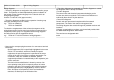
OV00.01-S-1901-03VA Use of wiring diagrams Wiring diagrams a The wiring diagrams are assigned to the familiar function groups 00-91. The systems are listed alphabetically with an indication of the function group/ function subgroup in the "Search aid for all wiring diagram groups" OV00.01-S-1901VA or A3 (paper version). a The wiring diagrams are filed in the respective function group arranged according to the PE number, e.g.: PE07.16-S-2000VA PE07.
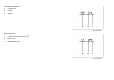
Connection designation a b Component Clutch c Socket P00.19-0402-01 Wire designation a Conductor cross-section in mm b Basic color c Identification color 2 P00.
Identification of truncated wires a Component to which the truncated electric line leads b Connection designation on component Fuse blocks a Receptacle numbering, output (A, B, C or D) b Line bridge c Terminal designation d Fuse rating in amp(s) e Receptacle numbering, input (E) f Fuse number
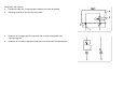
Components and switches a Component which are not represented completely are shown dismantled. b Switching contacts are shown in the rest position.
Looped lines a Function-specific components b The looped line connects two function-specific components across one or more functionindependent component connections. P00.19-2089-01 Indirect line (only for terminal 31 or terminal 58) a Function-specific component b Indirect line for more than two intermediate function-independent component connections/ loops.
Installation date a Installation of a component up to date b Installation of a component as of date P00.
Abbreviations for Wiring Diagrams 06/05 Transporters • Electrics <>Van - Electrical Systems Wiring Diagrams VITO (Model 639) Chapter 2
OV00.01-S-1001-27VA Abbreviations for wiring diagrams MODEL 639.601/603/605/701/703/ 705/711/713/811/813/815 Abbreviation Designation Code FG.FUG AB Airbag 91.00 ABL Exterior lights 82.10 ABS Antilock brake system 42.30 AT Automatic transmission G40 - Automatic transmission 27.19 AHV Trailer hitch Q22 - Fixed trailer hitch 31.
OCP Overhead control panel control unit LD0 - Dome lamp with reading lamp for driver/front passenger DTR Distronic (adaptive cruise control) IN18 - Distronic EDC Electronic diesel control 07.16 EDS Electronic diesel system 07 ATA Anti-theft alarm system EFH Power windows 72.29 ISC Electronic idle speed control 07 ELC Electronic level control CL0 - Rear lowerable/raisable air suspension 32.33 ESP Electronic stability program BB3 - Electronic Stability Program (ESP) 42.
HRA Headlamp range adjustment 82.10 ME-SFI ME-SFI fuel injection and ignition system 07.61 MT Manual transmission MOST Media Oriented System Transport REST Residual engine heat utilization system OSL Orthopedic seat backrest PTS Parktronic system RHD Right-hand drive vehicle SR Tilting/sliding roof HS Heated seats 82 EZ8 - Parktronic System (PTS) 54.65 D24 - Glass tilting/sliding roof in passenger compartment D27 - Glass tilting/sliding roof in driver compartment 54.
OV00.
A-P-EV1 Output - pulse width signal - injection valve, cyl. 1 A-P-EV2 Output - pulse width signal - injection valve, cyl. 2 A-P-EV3 Output - pulse width signal - injection valve, cyl. 3 A-P-EV4 Output - pulse width signal - injection valve, cyl.
A_Kl.
D- Dynamo, negative D+ Dynamo, positive D2B IN Input, digital data bus D2B OUT Output, digital data bus Daten IR Infrared DBE Overhead control panel DFA hi.li. Rpm sensor output, left rear DFA hi.re. Rpm sensor output, right rear DFA-HR Rpm sensor output, right rear DFHL Rpm sensor, left rear DFHR Rpm sensor, right rear DFVL Rpm sensor, left front DFVR Rpm sensor, right front Diag. Diagnosis Diag.
E-S-S+B Input - shift signal - set plus accelerate E-S-S-B Input - shift signal - set - accelerate (decelerate) E-S-v. Begr. Input - signal - variable limit E-S-WA Input - shift signal - resume ED Duty cycle EDW D ATA data EDW M Ground EDW-ZA ATA state display EHD Electrohydraulic pressure supply ELV Magnetabsch.
E_LSIA1 Input, O2 sensor, upstream from TWC E_LSIP1 Input, O2 sensor, upstream from TWC E_LSIP2 Input, common rail high pressure pump E_LSUN1 Input, O2 sensor, upstream from TWC E_LSVM1 Input, O2 sensor, upstream from TWC E_MOK Input, oil sensor (oil level, temperature and quality) E_NWDG Input, Hall sensor for camshaft E_P1 Input, pressure sensor, downstream from air filter E_P3 Input, charge pressure sensor E_PWG1 Input, pedal value sensor E_PWG2 Input, pedal value sensor E_RDS Inpu
GSLBF + Front passenger seat belt buckle, positive GSLFA+ Driver seat belt buckle, positive GUSFO li. - Left rear emergency tensioning retractor, negative GUSFO li.+ Left rear emergency tensioning retractor, positive GUSFO re. - Right rear emergency tensioning retractor, negative GUSFO re.
M-C-KWDGB Ground - crankshaft sensor M-R-LSVK Ground - oxygen sensor MBBVVR Ground, brake pad wear, right front MDFHL Ground, vehicle speed sensor, rear left MDFHR Ground, vehicle speed sensor, right rear MDFVL Ground, vehicle speed sensor, left front MDFVR Ground, vehicle rpm sensor, right front MH Engine hood Mikr. - Microphone negative Mikr.
M_TMOT Ground, coolant temperature sensor M_VDK Ground, intake air throttle valve actuator M_WSG Ground, fuel filter water level sensor N-R-NWHC Ground - camshaft Hall sensor NAV MUTE Navigation system muting NAV NF - Navigation low frequency negative NF Low frequency NF li Low frequency, left NF re Low frequency, right NOE Emergency opening NSL -LL Rear fog lamp - left-hand drive vehicle NSL -RL Rear fog lamp - right-hand drive vehicle NV Ancillary consumer (accessory) P1 Gearshi
Sig. Signal Sig. RF-Ant.
UB Voltage operation ÜKB Excess force limiter UMRFP Return flow pump monitor USP1 Voltage supply, set value potentiometer 1 USP2 Voltage supply, set value potentiometer 2 USV 1 Switchover solenoid valve 1 USV 2 Switchover solenoid valve 2 U_DPF Voltage supply, pressure differential sensor CAT (NAFTA) U_DRV Voltage supply, pressure regulator valve U_DRVa Voltage supply, pressure regulator valve U_EDW Voltage supply, interior protection sensor, rear U_HFMb Voltage supply, mass air flow
vo.li. + Left front positive vo.re. + Right front positive vo.re. - Right front negative VR AV Right front pressure reduction solenoid valve VR EV Right front pressure hold solenoid valve V_Signal_Eing. Input, mirror taximeter vehicle speed signal WALA See WL WL (SRS) Warning lamp (supplemental restraint system) ZA State display ZA-LED State displays - light emitting diode ZK Ignition circuit(s) Zp. AB, BF- Front passenger airbag squib, negative Zp.
Location and assignment of ground points 06/05 Transporters • Electrics <>Van - Electrical Systems Wiring Diagrams VITO (Model 639) Chapter 3
GF00.19-S-2000VB Location and assignment of ground points 19.7.05 MODEL 639.601 /603 /605 /701 /703 /705 /711 /713 /811 /813 /815 W10 Ground (battery) GF00.19-S-2000-04VB W10/4 Ground (additional battery) GF00.19-S-2000-05VB W12 Ground (cockpit and center console) GF00.19-S-2000-26VB W2 Ground (right front lamp unit) GF00.19-S-2000-02VB W2/1 Ground (right front ABS) GF00.19-S-2000-02VB W26 Ground (restraint systems control unit) GF00.19-S-2000-26VB W29/8 Ground (left D-pillar) GF00.
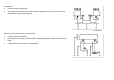
GF00.19-S-2000-01VB Location and assignment of ground points, engine compartment, left Model 639 N01.00-2433-06 Ground point Designation Copyright DaimlerChrysler AG 03.12.2005 CD-Ausgabe G/11/05 . This WIS print-out will not be recorded by Modification services. Component Designation Connector.
W9 W9/3 Ground (left front lamp unit) Ground (left front ABS) Copyright DaimlerChrysler AG 03.12.2005 CD-Ausgabe G/11/05 . This WIS print-out will not be recorded by Modification services. E1 Lamp unit, left front 3 E1 Lamp unit, left front 4 E1 Lamp unit, left front 8 E22/1 Additional turn signal lamp, left 2 K40/9 Fuse and relay block MK2.
GF00.19-S-2000-02VB Location and assignment of ground points, engine compartment, right Model 639 N62.20-2030-06 Ground point Designation Copyright DaimlerChrysler AG 03.12.2005 CD-Ausgabe G/11/05 . This WIS print-out will not be recorded by Modification services. Component Designation Connector.
W2 W2/1 Ground (right front lamp unit) Ground (right front ABS) Copyright DaimlerChrysler AG 03.12.2005 CD-Ausgabe G/11/05 . This WIS print-out will not be recorded by Modification services.
GF00.19-S-2000-04VB Arrangement and assignment of ground points interior left Type 639 N91.10-2171-11 Ground point Designation Component Designation Connector. Pin W10 G1 2 Ground (battery) Copyright DaimlerChrysler AG 03.12.2005 CD-Ausgabe G/11/05 . This WIS print-out will not be recorded by Modification services.
GF00.19-S-2000-05VB Location and assignment of ground points, interior compartment, right Type 639 N91.10-2170-11 Ground point Designation Component Designation Connector. Pin W10/4 G1/1 2 Ground (additional battery) Copyright DaimlerChrysler AG 03.12.2005 CD-Ausgabe G/11/05 . This WIS print-out will not be recorded by Modification services.
GF00.19-S-2000-21VB Location and assignment of ground points - rear- Type 639 end N64.20-2014-11 Copyright DaimlerChrysler AG 03.12.2005 CD-Ausgabe G/11/05 . This WIS print-out will not be recorded by Modification services.
N64.20-2015-11 Ground point Designation Copyright DaimlerChrysler AG 03.12.2005 CD-Ausgabe G/11/05 . This WIS print-out will not be recorded by Modification services. Comp-onent Designation Connector.
W29/8 W29/9 Ground (left D-pillar) Ground (right D-pillar) Copyright DaimlerChrysler AG 03.12.2005 CD-Ausgabe G/11/05 . This WIS print-out will not be recorded by Modification services. E3 Taillamp, left E22/3 Additional turn signal lamp, left rear N19/3 Rear AC control unit FONDKLA A. 4 N125 Telephone high frequency compensator 1.2 S81/1 Rear heater operating switch A.
GF00.19-S-2000-24VB Location and assignment of ground points - roof Model 639 N65.00-2028-11 Ground point Designation Component Designation Connector.
Copyright DaimlerChrysler AG 03.12.2005 CD-Ausgabe G/11/05 . This WIS print-out will not be recorded by Modification services. N70 Overhead control panel control unit 1.2 N70/1 Rear sliding roof unit control unit (SDE-H) 1.
GF00.19-S-2000-26VB Location and assignment of ground points center console Model 639 N68.20-2061-11 Copyright DaimlerChrysler AG 03.12.2005 CD-Ausgabe G/11/05 . This WIS print-out will not be recorded by Modification services.
N68.20-2062-11 Ground point Designation Copyright DaimlerChrysler AG 03.12.2005 CD-Ausgabe G/11/05 . This WIS print-out will not be recorded by Modification services. Component Designation Connector.
W12 W26 Ground (cockpit and center console) Ground (restraint systems control unit) Copyright DaimlerChrysler AG 03.12.2005 CD-Ausgabe G/11/05 . This WIS print-out will not be recorded by Modification services. A1 Instrument cluster 8 A1 Instrument cluster 12 A2/77 Telephone and communication unit j8.12 A2/77 Telephone and communication unit j8.13 A2/78 Audio-Video-Navigation (AVN) AB. A8 A35/11 SBS control unit 1.3 A35/13 D2B telephone transmitter/receiver 1.
Copyright DaimlerChrysler AG 03.12.2005 CD-Ausgabe G/11/05 . This WIS print-out will not be recorded by Modification services. A54 Thoraxbag and windowbag sensor, right 1 N2/2 SRS control unit 1.83 N2/2 SRS control unit 1.84 N2/10 SRS control unit 1.83 N2/10 SRS control unit 1.84 N2/11 ARCADE airbag control unit 1.15 N2/11 ARCADE airbag control unit 1.
GF00.19-S-2000-25VB Location and assignment of ground points - side panel Type 639 N63.00-2004-11 Ground point Designation Component Designation W33/4 W43/1 Ground (tank filler neck) Copyright DaimlerChrysler AG 03.12.2005 CD-Ausgabe G/11/05 . This WIS print-out will not be recorded by Modification services. Connector.
GF00.19-S-2000-30VB Location and assignment of ground points - left firewall Model 639 N62.25-2068-11 Ground point Designation Component Designation Connector. Pin W43/1 A6n1 STH control unit 1.2 K40/9 Fuse and relay block I1.6 M3/3 Fuel pump with fuel level sensor 4 M28/11 Lumbar support adjustment motor, right 2 M28/12 Lumbar support adjustment motor, left 2 M46/1 STH fuel metering pump 2 N10/16 COU [ZBE] control unit 1.8 N10/16 COU [ZBE] control unit 1.
Copyright DaimlerChrysler AG 03.12.2005 CD-Ausgabe G/11/05 . This WIS print-out will not be recorded by Modification services. N32/1 Left front seat adjustment control unit with memory 2.2 N32/2 Right front seat adjustment control unit with memory 2.2 N33/5 Hot air stationary heater control unit 1.10 N34 STH timer 1.4 N69/1 Door control unit, left front 2.
GF00.19-S-2000-34VB Location and assignment of ground points - right firewall Type 639 N62.25-2067-11 Ground point Designation Component Designation Connector. Pin W43/2 A6n1 STH control unit 1.2 B37/3 Pedal value sensor 2.2 K2 Headlamp cleaning system relay 4 K40/9 Fuse and relay block I1.6 M28/11 Lumbar support adjustment motor, right 2 M28/12 Lumbar support adjustment motor, left 2 N26/15 PSM control unit 2.3 N32/1 Left front seat adjustment control unit with memory 2.
Copyright DaimlerChrysler AG 03.12.2005 CD-Ausgabe G/11/05 . This WIS print-out will not be recorded by Modification services. N32/2 Right front seat adjustment control unit with memory 2.2 N62 PTS control unit 1.10 N69/2 Door control unit, right front 2.4 S12 Parking brake indicator switch 1 S40/3 Clutch pedal switch 1 X30/27 Engine CAN bus connector 1.
Location and assignment of plug connections 06/05 Transporters • Electrics <>Van - Electrical Systems Wiring Diagrams VITO (Model 639) Chapter 4
GF00.19-S-1000VB Location and assignment of line and plug connectors 19.7.05 X1/30 Speaker connector GF00.19-S-1000-05VB X8/20 Right rear-end door connector GF00.19-S-1000-20VB X8/22 Left rear-end door connector GF00.19-S-1000-20VB X11/32 Connector between selector lever module and data link connector GF00.19-S-1000-05VB X15 Engine fan 100 °C temperature switch connector GF00.19-S-1000-33VB X18/2 Load compartment lamp connector GF00.
GF00.19-S-1000-05VB Location and assignment of line and plug connectors, interior compartment, right Model 639 N68.10-2199-08 Code Designation Copyright DaimlerChrysler AG 03.12.2005 CD-Ausgabe G/11/05 . This WIS print-out will not be recorded by Modification services.
X1/30 X11/32 X18/2 X18/23 Speaker connector Connector between selector lever module and data link connector Load compartment lamp connector Telephone ON Telephone connector Copyright DaimlerChrysler AG 03.12.2005 CD-Ausgabe G/11/05 . This WIS print-out will not be recorded by Modification services.
X26/23 X30/24 X30/27 X54/12 Engine compartment to cockpit connector GNGY 3 GNGY GNWH 4 GNWH GNYE 5 GNYE BNBU 7 BNBU BURD 8 BURD green 9 GNWH BUVT 10 BU BUWH 11 BUWH BUGY 12 BUGY YERD 13 YERD YEWH 14 YEWH RDBU 15 RDBU GNYE 16 GNYE BKGN 17 BKGN BN 18 BN RDGN 19 RDGN BNGN 20 BNGN BKBU 21 BKBU 1 BNRD 2 BN 1 GNWH 2 GN 3 BNYE BKVT 1 BKVT BKGY 2 BKGY Interior CAN bus connector Engine CAN bus connector 2-pin heated seats connector, left an
X62/28 X72 Rpm sensor connector STH connector Copyright DaimlerChrysler AG 03.12.2005 CD-Ausgabe G/11/05 . This WIS print-out will not be recorded by Modification services.
GF00.19-S-1000-20VB Location and assignment of line and plug connectors - rear Model 639 N68.30-2073-12 Code Designation Copyright DaimlerChrysler AG 03.12.2005 CD-Ausgabe G/11/05 . This WIS print-out will not be recorded by Modification services.
X8/20 X8/22 X52 Right rear-end door connector Left rear-end door connector Trailer hitch connector Copyright DaimlerChrysler AG 03.12.2005 CD-Ausgabe G/11/05 . This WIS print-out will not be recorded by Modification services.
GF00.19-S-1000-24VB Location and assignment of line and plug connectors - underfloor Model 639 Shown on left side of vehicle S54.18-4517-05 Copyright DaimlerChrysler AG 12/3/05 G/11/05. This WIS printout will not be recorded by the update service.
Illustrated on right side of vehicle S35.00-4510-06 Code Designation X62/8 Rpm sensor and brake wear sensor connector, left rear Cable colors BK 1 GNRD WH 2 GNBN WH Copyright DaimlerChrysler AG 12/3/05 G/11/05. This WIS printout will not be recorded by the update service.
BK 2 BUBN WH 1 YE BK X62/21 X62/22 X62/39 X62/40 ABS/ASR rpm signal connector, left rear ABS/ASR rpm signal connector, right rear BBV rear axle connector, left BBV rear axle connector, right YEBN BK 1 green WH 2 GNRD WH 1 YE BK 2 YEBN WH 1 BU BK 2 BUBN BK 1 GN WH 2 GNRD BK WH Copyright DaimlerChrysler AG 12/3/05 G/11/05. This WIS printout will not be recorded by the update service.
GF00.19-S-1000-28VB Location and assignment of line and plug connectors - center console Code Designation X28/23 Airbag connector, driver and front passenger Model 639 Cable colors VT 1 GN 2 BUGN 3 BNBK Copyright DaimlerChrysler AG 12/3/05 G/11/05. This WIS printout will not be recorded by the update service.
N01.00-2432-06 Code Designation X15 Engine fan 100 °C temperature switch connector Cable colors RD 1 BN 2 BUVT Copyright DaimlerChrysler AG 12/3/05 G/11/05. This WIS printout will not be recorded by the update service.
BUWH X62/6 Rpm sensor and brake wear sensor connector, right front WH BK BK WH 4 1 2 YEVT VTGN WH 1 BK BK 2 BKYE BK 1 WH 2 3 4 Copyright DaimlerChrysler AG 12/3/05 G/11/05. This WIS printout will not be recorded by the update service.
Battery, starting charging circuit 06/05 Transporters • Electrics <>Van - Electrical Systems Wiring Diagrams VITO (Model 639) Chapter 5
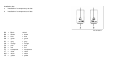
PE15.00-S-2000VA ENGINES ENGINES Wiring diagram for starter, alternator 25.3.03 646.982 /983, 112.951 /976, 642.990 up to 28.2.05 in MODELS 639.601 /603 /605 /701 /703 /705 up to 28.2.05 646.982, 112.951 /976, 642.990 up to 28.2.05 in MODELS 639.711 /713 /811 /813 /815 up to 28.2.05 PE15.00-S-2000-99VA Wiring diagram for starter, alternator PE15.00-S-2000-99VA PE15.00-S-2000-60VA Legend of wiring diagram for starter, alternator PE15.00-S-2000-60VA OV00.01-S-1901-03VA Use of wiring diagrams OV00.
PE15.00-S-2000-60VA Legend of wiring diagram for starter, alternator ENGINES 646.982 /983, 112.951 /976, 642.990 up to 28.2.05 in MODELS 639.601 /603 /605/ 701 /703 /705 up to 28.2.05 ENGINES 646.982, 112.951 /976, 642.990 up to 28.2.05 in MODELS 639.711 /713 /811/ 813 /815 up to 28.2.
U1080 Valid for alternator 14V / 200 A without automatic transmission 41F U150 Valid for engine M 112 24H 37B U740 Valid for engine OM 646 34H U999 Valid for engine OM 646 without automatic transmission 37A X22 Engine compartment and engine connector 3H Z66/1 Additional fuse box feed connector sleeve 30F Copyright DaimlerChrysler AG 03.12.2005 CD-Ausgabe G/11/05 . This WIS print-out will not be recorded by Modification services.
Copyright DaimlerChrysler AG 03.12.2005 CD-Ausgabe G/11/05 . This WIS print-out will not be recorded by Modification services.
Copyright DaimlerChrysler AG 03.12.2005 CD-Ausgabe G/11/05 . This WIS print-out will not be recorded by Modification services.
Copyright DaimlerChrysler AG 03.12.2005 CD-Ausgabe G/11/05 . This WIS print-out will not be recorded by Modification services.
PE15.00-S-2000VB ENGINES ENGINES Wiring diagram for starter, alternator 24.8.05 646.982 /983, 112.951 /976, 642.990 as of 1.3.05 in MODELS 639.601 /603 /605 /701 /703 /705 as of 1.3.05 646.982, 112.951 /976, 642.990 as of 1.3.05 in MODELS 639.711 /713 /811 /813 /815 as of 1.3.05 PE15.00-S-2000-99VB Wiring diagram for starter, alternator PE15.00-S-2000-99VB PE15.00-S-2000-60VB Legend of wiring diagram for starter, alternator PE15.00-S-2000-60VB OV00.01-S-1901-03VA Use of wiring diagrams OV00.
PE15.00-S-2000-60VB Legend of wiring diagram for starter, alternator ENGINES 646.982 /983, 112.951 /976, 642.990 from 1.3.05 in MODELS 639.601 /603 /605/ 701 /703 /705 from 1.3.05 ENGINES 646.982, 112.951 /976, 642.990 from 1.3.05 in MODELS 639.711 /713 /811/ 813 /815 from 1.3.
N33/4 Heater booster control unit 47L U53 Valid for automatic air conditioning "Thermotronic" 52H U54 Valid for regulated air conditioning "Tempmatic" 52H U1001 Valid for engine OM 646 with automatic transmission 15B U1002 Valid for PTC element 47H U1080 Valid for alternator 14V / 200 A without automatic transmission 23G U150 Valid for engine M 112 21B 50H U740 Valid for engine OM 646 58H U960 Valid for engine OM 642 1B 55H U999 Valid for engine OM 646 without automatic transmiss
Copyright DaimlerChrysler AG 03.12.2005 CD-Ausgabe G/11/05 . This WIS print-out will not be recorded by Modification services.
Copyright DaimlerChrysler AG 03.12.2005 CD-Ausgabe G/11/05 . This WIS print-out will not be recorded by Modification services.
Copyright DaimlerChrysler AG 03.12.2005 CD-Ausgabe G/11/05 . This WIS print-out will not be recorded by Modification services.
Copyright DaimlerChrysler AG 03.12.2005 CD-Ausgabe G/11/05 . This WIS print-out will not be recorded by Modification services.
Voltage supply fuses 06/05 Transporters • Electrics <>Van - Electrical Systems Wiring Diagrams VITO (Model 639) Chapter 6
PE54.15-S-2005VA Wiring diagram of voltage supply of fuses 25.3.03 MODEL 639.601 /603 /605 /701 /703 /705 /711 /713 /811 /813 /815 left seat frame PE54.15-S-2005-99VA Wiring diagram of voltage supply of fuses PE54.15-S-2005-99VA PE54.15-S-2005-60VA Legend of wiring diagram for voltage supply of fuses PE54.15-S-2005-60VA OV00.01-S-1901-03VA Use of wiring diagrams OV00.01-S-1901-03VA OV00.01-S-1901VA Search aid for all wiring diagram groups OV00.01-S-1901VA OV00.
PE54.15-S-2005-60VA Legend of wiring diagram for voltage supply of fuses MODEL 639.
N34 STH timer 22K N69/1 Door control unit, left front 6K N69/2 Door control unit, right front 9K U26 Valid for taxi version with emergency alarm system 11G U27 Valid for taxi version without emergency alarm system 11G U1025 Valid for warm air auxiliary heater with timer and temperature control 29G U1036 Valid for freezer vehicle 11H U1037 Valid for refrigerator vehicle 11H U1038 Valid for FUN equipment line with refrigerator box 16G 19B U1039 Valid for warm air auxiliary heater w
Copyright DaimlerChrysler AG 03.12.2005 CD-Ausgabe G/11/05 . This WIS print-out will not be recorded by Modification services.
Copyright DaimlerChrysler AG 03.12.2005 CD-Ausgabe G/11/05 . This WIS print-out will not be recorded by Modification services.
Copyright DaimlerChrysler AG 03.12.2005 CD-Ausgabe G/11/05 . This WIS print-out will not be recorded by Modification services.
PE54.15-S-2005VB Wiring diagram of voltage supply of fuses 25.7.03 MODEL 639.601 /603 /605 /701 /703 /705 /711 /713 /811 /813 /815 Sheet 1, E-box F34 PE54.15-S-2005-99VB Wiring diagram of voltage supply of fuses Sheet 1 PE54.15-S-2005-99VB PE54.15-S-2005-60VB Legend of wiring diagram for voltage supply of fuses Sheet 1 PE54.15-S-2005-60VB OV00.01-S-1901-03VA Use of wiring diagrams OV00.01-S-1901-03VA OV00.01-S-1901VA Search aid for all wiring diagram groups OV00.01-S-1901VA OV00.
PE54.15-S-2005-60VB Legend of wiring diagram for voltage supply of fuses MODEL 639.
N66/4 Rear conversation unit control unit 13K 75K N70 Overhead control panel control unit 58K N70/1 Rear sliding roof unit control unit (SDE-H) 65K N72/1 Upper control panel control unit 6K S1 Exterior lamp switch 4K S66/4 Rear entertainment system switch 11K S98 Air conditioning operating module 72K U15 Valid for screen in rear and DVD player 11D 75D U16 Valid for screen in rear, DVD player and TV tuner 11E 75E U37 Valid for ATA [EDW] I 57E U38 Valid for ATA [EDW] II 57E U5
U1017 Valid for electrohydraulic "Easy up" pop-up roof and glass sliding/lifting roof in driver area/front passenger area 62D U1018 Valid without EDW I 53H U1019 Valid without light/rain sensor 53H U1024 Valid for DBE with 2 reading spotlights or garage door opener without glass tilting/sliding roof in 59D driver/passenger compartment, glass tilting/sliding roof in passenger compartment, light/rain sensor, EDW II or EDW I U949 Valid for glass tilting/sliding roof in passenger compartment 57E U
Copyright DaimlerChrysler AG 03.12.2005 CD-Ausgabe G/11/05 . This WIS print-out will not be recorded by Modification services.
Copyright DaimlerChrysler AG 03.12.2005 CD-Ausgabe G/11/05 . This WIS print-out will not be recorded by Modification services.
Copyright DaimlerChrysler AG 03.12.2005 CD-Ausgabe G/11/05 . This WIS print-out will not be recorded by Modification services.
Copyright DaimlerChrysler AG 03.12.2005 CD-Ausgabe G/11/05 . This WIS print-out will not be recorded by Modification services.
Copyright DaimlerChrysler AG 03.12.2005 CD-Ausgabe G/11/05 . This WIS print-out will not be recorded by Modification services.
PE54.15-S-2005VC Wiring diagram of voltage supply of fuses 25.7.03 MODEL 639.601 /603 /605 /701 /703 /705 /711 /713 /811 /813 /815 Sheet 2, E-box F34 PE54.15-S-2005-99VC Wiring diagram of voltage supply of fuses Sheet 2 PE54.15-S-2005-99VC PE54.15-S-2005-60VC Legend of wiring diagram for voltage supply of fuses Sheet 2 PE54.15-S-2005-60VC OV00.01-S-1901-03VA Use of wiring diagrams OV00.01-S-1901-03VA OV00.01-S-1901VA Search aid for all wiring diagram groups OV00.01-S-1901VA OV00.
PE54.15-S-2005-60VC Legend of wiring diagram for voltage supply of fuses MODEL 639.
F34f41 Brake system delivery pump fuse 46B F34f42 Radio fuse or DIN navigation 57B H3/1 Alarm signal horn with additional battery 30K K2 Headlamp cleaning system relay 27K K23/1 Blower motor relay 41L N30/4 ESP control unit 45K N72/1 Upper control panel control unit 14K N73 EIS [EZS] control unit 33K N123 Hands-free system control unit 10L S98 Air conditioning operating module 36L U10 Valid for Sound 40 Pro radio 64D U11 Valid for radio with cassette drive, Latin America 6
U959 Valid for Audio 30 APS radio with TMC interface 54D U968 Valid for 1 day/2 driver tachograph 17D U998 Valid for auxiliary heater without air conditioning system 41G W12 Ground (cockpit and center console) 20L X31/9 Blower switch feed-in connector 36F Z66/1 Additional fuse box feed connector sleeve 2G Z151/3 A/C 1st stage connector sleeve 39H Copyright DaimlerChrysler AG 03.12.2005 CD-Ausgabe G/11/05 . This WIS print-out will not be recorded by Modification services.
Copyright DaimlerChrysler AG 03.12.2005 CD-Ausgabe G/11/05 . This WIS print-out will not be recorded by Modification services.
Copyright DaimlerChrysler AG 03.12.2005 CD-Ausgabe G/11/05 . This WIS print-out will not be recorded by Modification services.
Copyright DaimlerChrysler AG 03.12.2005 CD-Ausgabe G/11/05 . This WIS print-out will not be recorded by Modification services.
Copyright DaimlerChrysler AG 03.12.2005 CD-Ausgabe G/11/05 . This WIS print-out will not be recorded by Modification services.
PE54.15-S-2005VD Wiring diagram of voltage supply of fuses 25.8.05 MODEL 639.601 /603 /605 /701 /703 /705 /711 /713 /811 /813 /815 E-box F35 PE54.15-S-2005-99VD Wiring diagram of voltage supply of fuses PE54.15-S-2005-99VD PE54.15-S-2005-60VD Legend of wiring diagram for voltage supply of fuses PE54.15-S-2005-60VD OV00.01-S-1901-03VA Use of wiring diagrams OV00.01-S-1901-03VA OV00.01-S-1901VA Search aid for all wiring diagram groups OV00.01-S-1901VA OV00.
PE54.15-S-2005-60VD Legend of wiring diagram for voltage supply of fuses MODEL 639.
F35f38 Brake controller fuse (NAFTA) 70B F35f39 Front blower fuse 71B F35f40 Rear 12V socket fuse 73B F35f41 Additional turn signal module fuse 76B F35f42 Fuse 42 78B N9/1 Additional turn signal module control unit 76K N19/3 Rear AC control unit FONDKLA 66K N28/1 Trailer connection unit [AAG] control unit 18K 22K N32/1 Left front seat adjustment control unit with memory 26K N32/2 Right front seat adjustment control unit with memory 31K N51/3 ENR control unit 42K N62 PTS con
U939 Valid for socket for rear-mounted bicycle carrier repeater lamps 2E 15E 15G 18D 22D U940 Valid for electrical system for trailer socket 2D 15E 18E 22E U941 Valid for fixed trailer hitch 2H 15E 15G 18E 22E U942 Valid for removable trailer hitch 2H 15E 15H 18E 22E U945 Valid for warm water auxiliary heater 2F 63D U946 Valid for diesel heater booster 63D U951 Valid for raisable/lowerable rear air suspension 2D 41D U952 Valid for Tempmatic/Additional air conditioning in rear 2G 34D 3
X96/4 Rear recirculation unit connector 2 37F X137/1 VICS+ETC voltage supply separation point 61L Z51 ELC [ENR] terminal 30 connector sleeve 42G Z66/1 Additional fuse box feed connector sleeve 3G Copyright DaimlerChrysler AG 03.12.2005 CD-Ausgabe G/11/05 . This WIS print-out will not be recorded by Modification services.
Copyright DaimlerChrysler AG 03.12.2005 CD-Ausgabe G/11/05 . This WIS print-out will not be recorded by Modification services.
Copyright DaimlerChrysler AG 03.12.2005 CD-Ausgabe G/11/05 . This WIS print-out will not be recorded by Modification services.
Copyright DaimlerChrysler AG 03.12.2005 CD-Ausgabe G/11/05 . This WIS print-out will not be recorded by Modification services.
Copyright DaimlerChrysler AG 03.12.2005 CD-Ausgabe G/11/05 . This WIS print-out will not be recorded by Modification services.
Copyright DaimlerChrysler AG 03.12.2005 CD-Ausgabe G/11/05 . This WIS print-out will not be recorded by Modification services.
Fuse and relay board (SRB) 06/05 Transporters • Electrics <>Van - Electrical Systems Wiring Diagrams VITO (Model 639) Chapter 7
PE54.15-S-2001VA Wiring diagram for fuse and relay box 14.5.03 MODEL 639.601 /603 /605 /701 /703 /705 /711 /713 /811 /813 /815 Sheet 1 PE54.15-S-2001-99VA Wiring diagram for fuse and relay box Sheet 1 PE54.15-S-2001-99VA PE54.15-S-2001-60VA Legend of wiring diagram for fuse and relay box Sheet 1 PE54.15-S-2001-60VA OV00.01-S-1901-03VA Use of wiring diagrams OV00.01-S-1901-03VA OV00.01-S-1901VA Search aid for all wiring diagram groups OV00.01-S-1901VA OV00.
PE54.15-S-2001-60VA Legend for wiring diagram of fuse and relay box MODEL 639.
K40/9f21 Electronic selector lever module fuse 46K K40/9f22 Fuse, tachograph 47K K40/9f23 Airbag control unit fuse 49K K40/9f24 Fuse 45K K40/9f25 AAG fuse 47K K40/9f26 Cutoff relay fuse (Westfalia) 48K K40/9f27 Body manufacturer terminal 15 fuse 49K K40/9f28 Terminal 87 fuse, ETC [EGS] 52K K40/9f29 Fuse 51K K40/9f30 Fuse 50K K40/9f31 ATA [EDW] horn fuse 4K K40/9f32 Portable CTEL fuse, VICS 40K K40/9f33 Airbag control unit fuse, ACSR [AKSE] 41K K40/9f34 Body manufactur
K40/9k10 Terminal 15R relief relay 49C K40/9k11 Circuit 15 relief relay 54C M1 Starter 14L N10 SAM control unit 3B 22B 45B 66B Copyright DaimlerChrysler AG 03.12.2005 CD-Ausgabe G/11/05 . This WIS print-out will not be recorded by Modification services.
Copyright DaimlerChrysler AG 03.12.2005 CD-Ausgabe G/11/05 . This WIS print-out will not be recorded by Modification services.
Copyright DaimlerChrysler AG 03.12.2005 CD-Ausgabe G/11/05 . This WIS print-out will not be recorded by Modification services.
Copyright DaimlerChrysler AG 03.12.2005 CD-Ausgabe G/11/05 . This WIS print-out will not be recorded by Modification services.
Copyright DaimlerChrysler AG 03.12.2005 CD-Ausgabe G/11/05 . This WIS print-out will not be recorded by Modification services.
PE54.15-S-2001VC Wiring diagram for fuse and relay box 25.7.03 MODEL 639.601 /603 /605 /701 /703 /705 /711 /713 /811 /813 /815 Sheet 2 PE54.15-S-2001-99VC Wiring diagram for fuse and relay box Sheet 2 PE54.15-S-2001-99VC PE54.15-S-2001-60VC Legend of wiring diagram for fuse and relay box Sheet 2 PE54.15-S-2001-60VC OV00.01-S-1901-03VA Use of wiring diagrams OV00.01-S-1901-03VA OV00.01-S-1901VA Search aid for all wiring diagram groups OV00.01-S-1901VA OV00.
PE54.15-S-2001-60VC Legend of wiring diagram for fuse and relay box MODEL 639.
K57 Battery cutoff relay 47K N2/2 SRS control unit 31K N2/10 SRS control unit 34K N2/11 ARCADE airbag control unit 37K N15/3 EGS control unit 50K N15/5 Electronic selector lever module control unit 23K N28/1 Trailer connection unit [AAG] control unit 40K 43K U32 Valid for left-hand drive vehicles 17F U33 Valid for right-hand drive vehicles 20F U1031 Valid for additional heavy-duty battery 47D U1033 Valid for engine OM 646 with fuel filter with water separator and engine versio
X25/14 Connector for O2-sensor/exhaust gas temperature sensor 19E Z3/29 Circuit 15 connector sleeve (fused) 5G Z3/64 Circuit 15 connector sleeve 15E Copyright DaimlerChrysler AG 03.12.2005 CD-Ausgabe G/11/05 . This WIS print-out will not be recorded by Modification services.
Copyright DaimlerChrysler AG 03.12.2005 CD-Ausgabe G/11/05 . This WIS print-out will not be recorded by Modification services.
Copyright DaimlerChrysler AG 03.12.2005 CD-Ausgabe G/11/05 . This WIS print-out will not be recorded by Modification services.
Copyright DaimlerChrysler AG 03.12.2005 CD-Ausgabe G/11/05 . This WIS print-out will not be recorded by Modification services.
Copyright DaimlerChrysler AG 03.12.2005 CD-Ausgabe G/11/05 . This WIS print-out will not be recorded by Modification services.
PE54.15-S-2001VD Wiring diagram for fuse and relay box 25.7.03 MODEL 639.601 /603 /605 /701 /703 /705 /711 /713 /811 /813 /815 Sheet 3 PE54.15-S-2001-99VD Wiring diagram for fuse and relay box Sheet 3 PE54.15-S-2001-99VD PE54.15-S-2001-60VD Legend of wiring diagram for fuse and relay box Sheet 3 PE54.15-S-2001-60VD OV00.01-S-1901-03VA Use of wiring diagrams OV00.01-S-1901-03VA OV00.01-S-1901VA Search aid for all wiring diagram groups OV00.01-S-1901VA OV00.
PE54.15-S-2001-60VD Legend of wiring diagram for fuse and relay box MODEL 639.
N2/10 SRS control unit 12K N2/11 ARCADE airbag control unit 15K N3/9 CDI control unit 55K 62K N3/20 CDI control unit 58K 65K N66/4 Rear conversation unit control unit 51K N70 Overhead control panel control unit 22L N123 Hands-free system control unit 2K S109s3 Lumbar support adjustment switch, left front 26G 35G U15 Valid for screen in rear and DVD player 51D U16 Valid for screen in rear, DVD player and TV tuner 51D U32 Valid for left-hand drive vehicles 30F 40F U33 Valid f
W43/1 Ground (left interior compartment firewall) 31L 40L W43/2 Ground (right interior compartment firewall) 32L 42L X28/18 Seat occupied recognition with ACSR [AKSE] connector 18G X55/1 Left lumbar support adjustment connector 26E X55/2 Right lumbar support adjustment connector 35E X55/3 Left seat adjustment connector 26H X55/4 Right seat adjustment connector 35H X137/1 VICS+ETC voltage supply separation point 5K Copyright DaimlerChrysler AG 03.12.2005 CD-Ausgabe G/11/05 .
Copyright DaimlerChrysler AG 03.12.2005 CD-Ausgabe G/11/05 . This WIS print-out will not be recorded by Modification services.
Copyright DaimlerChrysler AG 03.12.2005 CD-Ausgabe G/11/05 . This WIS print-out will not be recorded by Modification services.
Copyright DaimlerChrysler AG 03.12.2005 CD-Ausgabe G/11/05 . This WIS print-out will not be recorded by Modification services.
Copyright DaimlerChrysler AG 03.12.2005 CD-Ausgabe G/11/05 . This WIS print-out will not be recorded by Modification services.
PE54.15-S-2001VE Wiring diagram for fuse and relay box 24.8.05 MODEL 639.601 /603 /605 /701 /703 /705 /711 /713 /811 /813 /815 Sheet 4 PE54.15-S-2001-99VE Wiring diagram for fuse and relay box PE54.15-S-2001-99VE PE54.15-S-2001-60VE Legend of wiring diagram for fuse and relay box PE54.15-S-2001-60VE OV00.01-S-1901-03VA Use of wiring diagrams OV00.01-S-1901-03VA OV00.01-S-1901VA Search aid for all wiring diagram groups OV00.01-S-1901VA OV00.
PE54.15-S-2001-60VE Legend of wiring diagram for fuse and relay box MODEL 639.
U939 Valid for socket for rear-mounted bicycle carrier repeater lamps 5D 8D U940 Valid for electrical system for trailer socket 5D 8D U941 Valid for fixed trailer hitch 5E 8E U942 Valid for removable trailer hitch 5E 8E U985 Valid for tailgate/hinged rear door window with wipe/wash system 12D W43/1 Ground (left interior compartment firewall) 34L W43/2 Ground (right interior compartment firewall) 32L X8/21 Tailgate connector 12G 18G X8/23 Left rear-end door connector 24G X20 Shift
Copyright DaimlerChrysler AG 03.12.2005 CD-Ausgabe G/11/05 . This WIS print-out will not be recorded by Modification services.
Copyright DaimlerChrysler AG 03.12.2005 CD-Ausgabe G/11/05 . This WIS print-out will not be recorded by Modification services.
Copyright DaimlerChrysler AG 03.12.2005 CD-Ausgabe G/11/05 . This WIS print-out will not be recorded by Modification services.
PE54.15-S-2001VF Wiring diagram for fuse and relay box 25.8.05 MODEL 639.601 /603 /605 /701 /703 /705 /711 /713 /811 /813 /815 Sheet 5 PE54.15-S-2001-99VF Wiring diagram for fuse and relay box PE54.15-S-2001-99VF PE54.15-S-2001-60VF Legend of wiring diagram for fuse and relay box PE54.15-S-2001-60VF OV00.01-S-1901-03VA Use of wiring diagrams OV00.01-S-1901-03VA OV00.01-S-1901VA Search aid for all wiring diagram groups OV00.01-S-1901VA OV00.
PE54.15-S-2001-60VF Legend of wiring diagram for fuse and relay box MODEL 639.
U1025 Valid for warm air auxiliary heater with timer and temperature control 6D U1044 Valid for FUN equipment line with warm air auxiliary heater with timer and temperature control 41D U507 Valid for Electronic Stability Program (ESP) 5D U909 Valid for radio preinstallation 23D U910 Valid for Sound 10 radio with cassette drive 17D U961 Valid for automatic transmission 2D 5D W12 Ground (cockpit and center console) 29L X11 Data link connector 5L Z3/11 Terminal 15 connector sleeve 10G
Copyright DaimlerChrysler AG 03.12.2005 CD-Ausgabe G/11/05 . This WIS print-out will not be recorded by Modification services.
Copyright DaimlerChrysler AG 03.12.2005 CD-Ausgabe G/11/05 . This WIS print-out will not be recorded by Modification services.
Copyright DaimlerChrysler AG 03.12.2005 CD-Ausgabe G/11/05 . This WIS print-out will not be recorded by Modification services.
Signal acquisition and actuation module (SAM) 06/05 Transporters • Electrics <>Van - Electrical Systems Wiring Diagrams VITO (Model 639) Chapter 8
PE54.21-S-2127VA Wiring diagram for signal acquisition and actuation module (SAM) control unit 14.5.03 MODEL 639.601 /603 /605 /701 /703 /705 /711 /713 /811 /813 /815 Sheet 1 PE54.21-S-2127-99VA Wiring diagram for signal acquisition and actuation module (SAM) control unit Sheet 1 PE54.21-S-2127-99VA PE54.21-S-2127-60VA Legend of wiring diagram for signal acquisition and actuation module (SAM) control unit Sheet 1 PE54.21-S-2127-60VA OV00.01-S-1901-03VA Use of wiring diagrams OV00.
PE54.21-S-2127-60VA Legend of wiring diagram for signal acquisition and actuation module (SAM) control unit MODEL 639.
U32 Valid for left-hand drive vehicles 58E 72E U33 Valid for right-hand drive vehicles 61E 75E U1081 Valid for 6-speed manual transmission, NSG 250 12D U1082 Valid for 6-speed manual transmission, NSG 370 12D U904 Valid for qualification as passenger car 28D 42D U927 Valid without backup warning system 49G U928 Valid for headlamp cleaning system 3C U964 Valid without electrically adjustable and heated outside rearview mirror 29F 42F U976 Valid for additional turn signal lamps on rea
Copyright DaimlerChrysler AG 03.12.2005 CD-Ausgabe G/11/05 . This WIS print-out will not be recorded by Modification services.
Copyright DaimlerChrysler AG 03.12.2005 CD-Ausgabe G/11/05 . This WIS print-out will not be recorded by Modification services.
Copyright DaimlerChrysler AG 03.12.2005 CD-Ausgabe G/11/05 . This WIS print-out will not be recorded by Modification services.
Copyright DaimlerChrysler AG 03.12.2005 CD-Ausgabe G/11/05 . This WIS print-out will not be recorded by Modification services.
Copyright DaimlerChrysler AG 03.12.2005 CD-Ausgabe G/11/05 . This WIS print-out will not be recorded by Modification services.
PE54.21-S-2127VB Wiring diagram for signal acquisition and actuation module (SAM) control unit 25.7.03 MODEL 639.601 /603 /605 /701 /703 /705 /711 /713 /811 /813 /815 Sheet 2 PE54.21-S-2127-99VB Wiring diagram for signal acquisition and actuation module (SAM) control unit Sheet 2 PE54.21-S-2127-99VB PE54.21-S-2127-60VB Legend of wiring diagram for signal acquisition and actuation module (SAM) control unit Sheet 2 PE54.21-S-2127-60VB OV00.01-S-1901-03VA Use of wiring diagrams OV00.
PE54.21-S-2127-60VB Legend of wiring diagram for signal acquisition and actuation module (SAM) control unit MODEL 639.
N10 SAM control unit 3A 11A 18A 26A 34A 42A 50A 56A N66/4 Rear conversation unit control unit 67K S10/3 Brake pad contact sensor, left rear 34K S10/4 Brake pad contact sensor, right rear 36K S12 Parking brake indicator switch 21L S49/7 Rotary tumbler switch, left rear-end door 45K U10 Valid for Sound 40 Pro radio 63D 63F U15 Valid for screen in rear and DVD player 63D 66F U16 Valid for screen in rear, DVD player and TV tuner 63D 66F U25 Valid for backup warning system 63E 69F U
U926 Valid for 270° 2-wing rear-end door 2D 9D 28E 43D U976 Valid for additional turn signal lamps on rear of roof 57D U977 Valid for additional turn signal lamps on rear of roof 52D U985 Window in tailgate/hinged rear door with wipe/wash system 25D W29/9 Ground (right D-pillar) 72L W43/1 Ground (left interior compartment firewall) 22L W43/2 Ground (right interior compartment firewall) 23L X8/20 Right rear-end door connector 6F 16E 43F 49F X8/21 Tailgate connector 26F 31F X8/22 L
Copyright DaimlerChrysler AG 03.12.2005 CD-Ausgabe G/11/05 . This WIS print-out will not be recorded by Modification services.
Copyright DaimlerChrysler AG 03.12.2005 CD-Ausgabe G/11/05 . This WIS print-out will not be recorded by Modification services.
Copyright DaimlerChrysler AG 03.12.2005 CD-Ausgabe G/11/05 . This WIS print-out will not be recorded by Modification services.
Copyright DaimlerChrysler AG 03.12.2005 CD-Ausgabe G/11/05 . This WIS print-out will not be recorded by Modification services.
Copyright DaimlerChrysler AG 03.12.2005 CD-Ausgabe G/11/05 . This WIS print-out will not be recorded by Modification services.
PE54.21-S-2127VC Wiring diagram for signal acquisition and actuation module (SAM) control unit 25.7.03 MODEL 639.601 /603 /605 /701 /703 /705 /711 /713 /811 /813 /815 Sheet 3 PE54.21-S-2127-99VC Wiring diagram for signal acquisition and actuation module (SAM) control unit Sheet 3 PE54.21-S-2127-99VC PE54.21-S-2127-60VC Legend of wiring diagram for signal acquisition and actuation module (SAM) control unit Sheet 3 PE54.21-S-2127-60VC OV00.01-S-1901-03VA Use of wiring diagrams OV00.
PE54.21-S-2127-60VC Legend of wiring diagram for signal acquisition and actuation module (SAM) control unit MODEL 639.
S21/13 Left vent window button 11L S21/14 Right vent window button 14L S49/6 Rotary tumbler switch, right rear-end door 46L 64L U1034 Valid for vehicles with ESP/ABS 68A U1035 Valid for vehicles without ESP/ABS 73A U1083 Valid for electric pop-out window in rear of passenger compartment 11D U924 Valid for tailgate 39G 57G U925 Valid for 180° 2-wing rear-end door 42G 61G U926 Valid for 270° 2-wing rear-end door 42G 61G U930 Valid for left load compartment sliding door 1D 49D U93
Copyright DaimlerChrysler AG 03.12.2005 CD-Ausgabe G/11/05 . This WIS print-out will not be recorded by Modification services.
Copyright DaimlerChrysler AG 03.12.2005 CD-Ausgabe G/11/05 . This WIS print-out will not be recorded by Modification services.
Copyright DaimlerChrysler AG 03.12.2005 CD-Ausgabe G/11/05 . This WIS print-out will not be recorded by Modification services.
Copyright DaimlerChrysler AG 03.12.2005 CD-Ausgabe G/11/05 . This WIS print-out will not be recorded by Modification services.
Copyright DaimlerChrysler AG 03.12.2005 CD-Ausgabe G/11/05 . This WIS print-out will not be recorded by Modification services.
PE54.21-S-2127VD Wiring diagram for signal acquisition and actuation module (SAM) control unit 25.8.05 MODEL 639.601 /603 /605 /701 /703 /705 /711 /713 /811 /813 /815 Sheet 4 PE54.21-S-2127-99VD Wiring diagram for signal acquisition and actuation module (SAM) control unit PE54.21-S-2127-99VD PE54.21-S-2127-60VD Legend of wiring diagram for signal acquisition and actuation module (SAM) control unit PE54.21-S-2127-60VD OV00.01-S-1901-03VA Use of wiring diagrams OV00.01-S-1901-03VA OV00.
PE54.21-S-2127-60VD Legend of wiring diagram for signal acquisition and actuation module (SAM) control unit MODEL 639.
S41 Fill level switch, coolant 18L S42 Fill level switch, window washer fluid 6L U32 Valid for left-hand drive vehicles 21G 25D 32D U33 Valid for right-hand drive vehicles 22G 28D 35D U37 Valid for ATA [EDW] I 49E U38 Valid for ATA [EDW] II 49E U1003 Valid for additional interior lamp in passenger compartment 67D U1004 Valid for interior lamp in rear 67E U1005 Valid without additional interior lamp in passenger compartment 71C U1006 Valid without interior lamp in rear 70G 71D U
U982 Valid for MPV 66G U983 Valid for TREND equipment line 66H U984 Valid for AMBIENTE equipment line 66H U987 Valid without DBE with 2 reading spotlights 57F W2 Ground (right front lamp unit) 22L W9 Ground (left front lamp unit) 21L W38 Ground (roof) 57L X18/2 Load compartment lamp connector 70F X18/29 Connector 1, left engine compartment or right engine compartment 33F X18/30 Connector 2, left engine compartment or right engine compartment 29F X30/24 Interior CAN bus connect
Copyright DaimlerChrysler AG 03.12.2005 CD-Ausgabe G/11/05 . This WIS print-out will not be recorded by Modification services.
Copyright DaimlerChrysler AG 03.12.2005 CD-Ausgabe G/11/05 . This WIS print-out will not be recorded by Modification services.
Copyright DaimlerChrysler AG 03.12.2005 CD-Ausgabe G/11/05 . This WIS print-out will not be recorded by Modification services.
Copyright DaimlerChrysler AG 03.12.2005 CD-Ausgabe G/11/05 . This WIS print-out will not be recorded by Modification services.
Copyright DaimlerChrysler AG 03.12.2005 CD-Ausgabe G/11/05 . This WIS print-out will not be recorded by Modification services.
Exterior lights 06/05 Transporters • Electrics <>Van - Electrical Systems Wiring Diagrams VITO (Model 639) Chapter 9
PE82.10-S-2000VA Wiring diagram of exterior lights 25.3.03 MODEL 639.601 /603 /605 /701 /703 /705 /711 /713 /811 /813 /815 except CODE (L84) Additional turn signal lamps on rear of roof PE82.10-S-2000-99VA Wiring diagram of exterior lights PE82.10-S-2000-99VA PE82.10-S-2000-60VA Legend for wiring diagram of exterior lights PE82.10-S-2000-60VA OV00.01-S-1901-03VA Use of wiring diagrams OV00.01-S-1901-03VA OV00.01-S-1901VA Search aid for all wiring diagram groups OV00.01-S-1901VA OV00.
PE82.10-S-2000-60VA Legend for wiring diagram of exterior lights MODEL 639.
W2 Ground (right front lamp unit) 43L 50L W9 Ground (left front lamp unit) 30L 37L Z3/11 Terminal 15 connector sleeve 19G Z36/6 HRA [LWR] power supply connector sleeve 26F 40G Z36/12 HRA [LWR] control bus connector sleeve 25F 39G Z66/1 Additional fuse box feed connector sleeve 4J Copyright DaimlerChrysler AG 03.12.2005 CD-Ausgabe G/11/05 . This WIS print-out will not be recorded by Modification services.
Copyright DaimlerChrysler AG 03.12.2005 CD-Ausgabe G/11/05 . This WIS print-out will not be recorded by Modification services.
Copyright DaimlerChrysler AG 03.12.2005 CD-Ausgabe G/11/05 . This WIS print-out will not be recorded by Modification services.
Copyright DaimlerChrysler AG 03.12.2005 CD-Ausgabe G/11/05 . This WIS print-out will not be recorded by Modification services.
PE82.10-S-2000VB Wiring diagram of exterior lights 25.8.05 MODEL 639.601 /603 /605 /701 /703 /705 /711 /713 /811 /813 /815 with CODE (L84) Additional turn signal lamps on rear of roof PE82.10-S-2000-99VB Wiring diagram of exterior lights PE82.10-S-2000-99VB PE82.10-S-2000-60VB Legend for wiring diagram of exterior lights PE82.10-S-2000-60VB OV00.01-S-1901-03VA Use of wiring diagrams OV00.01-S-1901-03VA OV00.01-S-1901VA Search aid for all wiring diagram groups OV00.01-S-1901VA OV00.
PE82.10-S-2000-60VB Legend for wiring diagram of exterior lights MODEL 639.
N10 SAM control unit 3K 14K 17K 32L 43L 46L U10 Valid for Sound 40 Pro radio 11G 40H U15 Valid for screen in rear and DVD player 11F 40H U16 Valid for screen in rear, DVD player and TV tuner 11G 40H U25 Valid for backup warning system 11G 40J U32 Valid for left-hand drive vehicles 15C 45C U33 Valid for right-hand drive vehicles 18C 48C U904 Valid for qualification as passenger car 7D 23D 35F 53F U976 Valid for additional turn signal lamps on rear of roof 29A U977 Valid without ad
Copyright DaimlerChrysler AG 03.12.2005 CD-Ausgabe G/11/05 . This WIS print-out will not be recorded by Modification services.
Copyright DaimlerChrysler AG 03.12.2005 CD-Ausgabe G/11/05 . This WIS print-out will not be recorded by Modification services.
Copyright DaimlerChrysler AG 03.12.2005 CD-Ausgabe G/11/05 . This WIS print-out will not be recorded by Modification services.
Copyright DaimlerChrysler AG 03.12.2005 CD-Ausgabe G/11/05 . This WIS print-out will not be recorded by Modification services.
Central locking 06/05 Transporters • Electrics <>Van - Electrical Systems Wiring Diagrams VITO (Model 639) Chapter 10
PE80.20-S-2000VA Wiring diagram of central locking (CL) 25.3.03 MODEL 639.601 /603 /605 /701 /703 /705 /711 /713 /811 /813 /815 with CODE (T19) Left sliding door PE80.20-S-2000-99VA Wiring diagram of central locking (CL) PE80.20-S-2000-99VA PE80.20-S-2000-60VA Legend of wiring diagram for central locking (CL) PE80.20-S-2000-60VA OV00.01-S-1901-03VA Use of wiring diagrams OV00.01-S-1901-03VA OV00.01-S-1901VA Search aid for all wiring diagram groups OV00.01-S-1901VA OV00.
PE80.20-S-2000-60VA Legend of wiring diagram for central locking (CL) MODEL 639.
S49/7 Rotary tumbler switch, left rear-end door 72L U32 Valid for left-hand drive vehicles 8C U33 Valid for right-hand drive vehicles 26C U49 Valid for Japan 48D U1020 Valid for convenience opening/closing with IR remote control 9D 26D U1111 Valid for vehicle ident end. no. 148282 12D 30D U1112 Valid as of vehicle ident. end no.
Copyright DaimlerChrysler AG 03.12.2005 CD-Ausgabe G/11/05 . This WIS print-out will not be recorded by Modification services.
Copyright DaimlerChrysler AG 03.12.2005 CD-Ausgabe G/11/05 . This WIS print-out will not be recorded by Modification services.
Copyright DaimlerChrysler AG 03.12.2005 CD-Ausgabe G/11/05 . This WIS print-out will not be recorded by Modification services.
Copyright DaimlerChrysler AG 03.12.2005 CD-Ausgabe G/11/05 . This WIS print-out will not be recorded by Modification services.
Copyright DaimlerChrysler AG 03.12.2005 CD-Ausgabe G/11/05 . This WIS print-out will not be recorded by Modification services.
CAN bus 06/05 Transporters • Electrics <>Van - Electrical Systems Wiring Diagrams VITO (Model 639) Chapter 11
PE00.19-S-2150VA Wiring diagram of CAN bus 25.3.03 MODEL 639.601 /603 /605 /701 /703 /705 /711 /713 /811 /813 /815 Sheet 1 PE00.19-S-2150-99VA Wiring diagram of CAN bus Sheet 1 PE00.19-S-2150-99VA PE00.19-S-2150-60VA Legend for electric wiring diagrams of CAN bus Sheet 1 PE00.19-S-2150-60VA OV00.01-S-1901-03VA Use of wiring diagrams OV00.01-S-1901-03VA OV00.01-S-1901VA Search aid for all wiring diagram groups OV00.01-S-1901VA OV00.
PE00.19-S-2150-60VA Legend for electric wiring diagrams of CAN bus MODEL 639.
U1016 Valid for glass tilting/sliding roof in passenger compartment without roof and rear-end doors, high version 44D U1017 Valid for electrohydraulic "Easy up" pop-up roof and glass tilting/sliding roof in driver/front passenger compartment 49E 58D U1107 Valid up to08/2005 9D 22D U1108 Valid as of09/2005 13D 30D U285 Valid for partially electric seat adjustment, driver 49E 62D U286 Valid for partially electric seat adjustment, front passenger 49E 65D U538 Valid for Parktronic System 37D
X8/25 Sliding roof in pop-up roof separation point (Westfalia) 59L X30/24 Interior CAN bus connector 15A 26A 42A 56A 64A 71A X30/25 Interior CAN bus connector 15A 26A 42A 56A 64A 71A X30/26 Interior CAN bus connector 15A 26A 42A 56A 64A 71A Copyright DaimlerChrysler AG 03.12.2005 CD-Ausgabe G/11/05 . This WIS print-out will not be recorded by Modification services.
Copyright DaimlerChrysler AG 03.12.2005 CD-Ausgabe G/11/05 . This WIS print-out will not be recorded by Modification services.
Copyright DaimlerChrysler AG 03.12.2005 CD-Ausgabe G/11/05 . This WIS print-out will not be recorded by Modification services.
Copyright DaimlerChrysler AG 03.12.2005 CD-Ausgabe G/11/05 . This WIS print-out will not be recorded by Modification services.
Copyright DaimlerChrysler AG 03.12.2005 CD-Ausgabe G/11/05 . This WIS print-out will not be recorded by Modification services.
PE00.19-S-2150VB Wiring diagram of CAN bus 25.7.03 MODEL 639.601 /603 /605 /701 /703 /705 /711 /713 /811 /813 /815 Sheet 2 PE00.19-S-2150-99VB Wiring diagram of CAN bus Sheet 2 PE00.19-S-2150-99VB PE00.19-S-2150-60VB Legend for electric wiring diagrams of CAN bus Sheet 2 PE00.19-S-2150-60VB OV00.01-S-1901-03VA Use of wiring diagrams OV00.01-S-1901-03VA OV00.01-S-1901VA Search aid for all wiring diagram groups OV00.01-S-1901VA OV00.
PE00.19-S-2150-60VB Legend for electric wiring diagrams of CAN bus MODEL 639.
U150 Valid for engine M 112 45D U507 Valid for Electronic Stability Program (ESP) 55D U740 Valid for engine OM 646 48D U955 Valid for alternator 14V / 200 Ah 16E U956 Valid for auto pilot system for Japan, large display 30D U957 Valid for Audio 10 radio with cassette drive 19D U958 Valid for Audio 10 radio with CD 19E U959 Valid for Audio 30 APS radio with TMC interface 23D U960 Valid for engine OM 642 41D U961 Valid for automatic transmission 64D W43/2 Ground (right interior
Copyright DaimlerChrysler AG 03.12.2005 CD-Ausgabe G/11/05 . This WIS print-out will not be recorded by Modification services.
Copyright DaimlerChrysler AG 03.12.2005 CD-Ausgabe G/11/05 . This WIS print-out will not be recorded by Modification services.
Copyright DaimlerChrysler AG 03.12.2005 CD-Ausgabe G/11/05 . This WIS print-out will not be recorded by Modification services.
Copyright DaimlerChrysler AG 03.12.2005 CD-Ausgabe G/11/05 . This WIS print-out will not be recorded by Modification services.
Instrument cluster 06/05 Transporters • Electrics <>Van - Electrical Systems Wiring Diagrams VITO (Model 639) Chapter 12
PE54.30-S-2000VA Wiring diagram of instrument cluster (IC)/gages/warning devices 14.5.03 MODEL 639.601 /603 /605 /701 /703 /705 /711 /713 /811 /813 /815 PE54.30-S-2000-99VA Wiring diagram of instrument cluster (IC)/gages/warning devices PE54.30-S-2000-99VA PE54.30-S-2000-60VA Legend of wiring diagram for instrument cluster (CLUS) / display instruments / warning devices PE54.30-S-2000-60VA OV00.01-S-1901-03VA Use of wiring diagrams OV00.01-S-1901-03VA OV00.
PE54.30-S-2000-60VA Legend of wiring diagram for instrument cluster (CLUS) / display instruments / warning devices MODEL 639.
U912 Valid for 1 day/2 driver tachograph and without automatic transmission 27G W12 Ground (cockpit and center console) 2L 21L X2/5 Tachograph connector 16E 30E X30/24 Interior CAN bus connector 6L X30/25 Interior CAN bus connector 6K X30/26 Interior CAN bus connector 6K X30/27 Engine CAN bus connector 3L Z3/11 Terminal 15 connector sleeve 11E Z60 Speed-dependent volume control signal connector sleeve 42E Copyright DaimlerChrysler AG 03.12.2005 CD-Ausgabe G/11/05 .
Copyright DaimlerChrysler AG 03.12.2005 CD-Ausgabe G/11/05 . This WIS print-out will not be recorded by Modification services.
Copyright DaimlerChrysler AG 03.12.2005 CD-Ausgabe G/11/05 . This WIS print-out will not be recorded by Modification services.
Copyright DaimlerChrysler AG 03.12.2005 CD-Ausgabe G/11/05 . This WIS print-out will not be recorded by Modification services.
Electronic ignition switch (EIS) 06/05 Transporters • Electrics <>Van - Electrical Systems Wiring Diagrams VITO (Model 639) Chapter 13
PE54.21-S-2104VA Wiring diagram of electronic ignition switch (EIS) control unit 25.3.03 MODEL 639.601 /603 /605 /701 /703 /705 /711 /713 /811 /813 /815 PE54.21-S-2104-99VA Wiring diagram of electronic ignition switch (EIS) control unit PE54.21-S-2104-99VA PE54.21-S-2104-60VA Legend of wiring diagram for electronic ignition switch control unit (EIS) PE54.21-S-2104-60VA OV00.01-S-1901-03VA Use of wiring diagrams OV00.01-S-1901-03VA OV00.
PE54.21-S-2104-60VA Legend of wiring diagram for electronic ignition switch control unit (EIS) MODEL 639.
Copyright DaimlerChrysler AG 03.12.2005 CD-Ausgabe G/11/05 . This WIS print-out will not be recorded by Modification services.
Copyright DaimlerChrysler AG 03.12.2005 CD-Ausgabe G/11/05 . This WIS print-out will not be recorded by Modification services.
Copyright DaimlerChrysler AG 03.12.2005 CD-Ausgabe G/11/05 . This WIS print-out will not be recorded by Modification services.
Electronic stability control (ESP) 06/05 Transporters • Electrics <>Van - Electrical Systems Wiring Diagrams VITO (Model 639) Chapter 14
PE42.45-S-2000VA Wiring diagram - electronic stability program (ESP) 25.3.03 MODEL 639.601 /603 /605 /701 /703 /705 /711 /713 /811 /813 /815 with CODE (BB3) Electronic Stability Program (ESP) PE42.45-S-2000-99VA Wiring diagram - electronic stability program (ESP) PE42.45-S-2000-99VA PE42.45-S-2000-60VA electronic stability program PE42.45-S-2000-60VA OV00.01-S-1901-03VA Use of wiring diagrams OV00.01-S-1901-03VA OV00.01-S-1901VA Search aid for all wiring diagram groups OV00.01-S-1901VA OV00.
PE42.45-S-2000-60VA electronic stability program MODEL 639.
S9/1 Stop lamp switch 17K U32 Valid for left-hand drive vehicles 6D 50D 56D U33 Valid for right-hand drive vehicles 8D 52D 59D U920 Valid up to vehicle identification end no. 30230 40D U921 Valid as of vehicle identification end no.
Copyright DaimlerChrysler AG 03.12.2005 CD-Ausgabe G/11/05 . This WIS print-out will not be recorded by Modification services.
Copyright DaimlerChrysler AG 03.12.2005 CD-Ausgabe G/11/05 . This WIS print-out will not be recorded by Modification services.
Copyright DaimlerChrysler AG 03.12.2005 CD-Ausgabe G/11/05 . This WIS print-out will not be recorded by Modification services.
Copyright DaimlerChrysler AG 03.12.2005 CD-Ausgabe G/11/05 . This WIS print-out will not be recorded by Modification services.
Common rail diesel injection (CDI) 06/05 Transporters • Electrics <>Van - Electrical Systems Wiring Diagrams VITO (Model 639) Chapter 15
PE07.16-S-2000VA Wiring diagram for common rail diesel injection (CDI) control unit 25.3.03 ENGINE 646.982 /983 in MODELS 639.601 /603 /605 /701 /703 /705 Sheet 1 ENGINE 646.982 in MODELS 639.711 /713 /811 /813 /815 Sheet 1 PE07.16-S-2000-99VA Wiring diagram for common rail diesel injection (CDI) control unit Sheet 1 PE07.16-S-2000-99VA PE07.16-S-2000-60VA Legend of wiring diagram for common rail diesel Sheet 1 injection (CDI) PE07.16-S-2000-60VA OV00.01-S-1901-03VA Use of wiring diagrams OV00.
PE07.16-S-2000-60VA Legend of wiring diagram for common rail diesel injection (CDI) ENGINE ENGINE 646.982 /983 in MODELS 639.601 /603 /605 /701 / 703 /705 Sheet 1 646.982 in MODELS 639.
U1114 Valid as of 01/2006 23D U559 Valid for cruise control 31E U961 Valid for automatic transmission 6D 31D U990 Valid without automatic transmission 34D W2 Ground (right front lamp unit) 19L 41L W9 Ground (left front lamp unit) 17L 40L W43/2 Ground (right interior compartment firewall) 33L X11 Data link connector 3L X22 Engine compartment and engine connector 6F X30/27 Engine CAN bus connector 20K Y77/1 Charge pressure control vacuum transducer 37L Copyright DaimlerChrysle
Copyright DaimlerChrysler AG 03.12.2005 CD-Ausgabe G/11/05 . This WIS print-out will not be recorded by Modification services.
Copyright DaimlerChrysler AG 03.12.2005 CD-Ausgabe G/11/05 . This WIS print-out will not be recorded by Modification services.
Copyright DaimlerChrysler AG 03.12.2005 CD-Ausgabe G/11/05 . This WIS print-out will not be recorded by Modification services.
Copyright DaimlerChrysler AG 03.12.2005 CD-Ausgabe G/11/05 . This WIS print-out will not be recorded by Modification services.
PE07.16-S-2000VB Wiring diagram for common rail diesel injection (CDI) control unit 25.7.03 ENGINE 646.982 /983 in MODELS 639.601 /603 /605 /701 /703 /705 Sheet 2 ENGINE 646.982 in MODELS 639.711 /713 /811 /813 /815 Sheet 2 PE07.16-S-2000-99VB Wiring diagram for common rail diesel injection (CDI) control unit Sheet 2 PE07.16-S-2000-99VB PE07.16-S-2000-60VB Legend of wiring diagram for common rail diesel Sheet 2 injection (CDI) PE07.16-S-2000-60VB OV00.01-S-1901-03VA Use of wiring diagrams OV00.
PE07.16-S-2000-60VB Legend of wiring diagram for common rail diesel injection (CDI) ENGINES 646.982 /983 in MODELS 639.601 /603 /605 /701 / 703 /705 Sheet 2 ENGINE 646.982 in MODELS 639.
K40/9f10 Engine components voltage supply fuse 50K K40/9f20 Ignition coil M112 fuse 12K L5/7 Crankshaft position sensor 26L M16/9 Intake air throttle valve actuator 45L N3/9 CDI control unit 6A 13A 20A 27A 33A 40A 47A 54A 61A R39/1 Vent line heater element 10L U32 Valid for left-hand drive vehicles 57F 62F U33 Valid for right-hand drive vehicles 59F 64F U961 Valid for automatic transmission 52D U991 Valid for particulate filter 55D U992 Valid for low emission vehicle EU4 Group
Y76/4 Cylinder 4 fuel injector 8L Y83 Inlet port shutoff switchover valve 43L Y94 Quantity control valve 36L Z7/24 Circuit 87 connector sleeve 50F Copyright DaimlerChrysler AG 03.12.2005 CD-Ausgabe G/11/05 . This WIS print-out will not be recorded by Modification services.
Copyright DaimlerChrysler AG 03.12.2005 CD-Ausgabe G/11/05 . This WIS print-out will not be recorded by Modification services.
Copyright DaimlerChrysler AG 03.12.2005 CD-Ausgabe G/11/05 . This WIS print-out will not be recorded by Modification services.
Copyright DaimlerChrysler AG 03.12.2005 CD-Ausgabe G/11/05 . This WIS print-out will not be recorded by Modification services.
Copyright DaimlerChrysler AG 03.12.2005 CD-Ausgabe G/11/05 . This WIS print-out will not be recorded by Modification services.
Standard heater 06/05 Transporters • Electrics <>Van - Electrical Systems Wiring Diagrams VITO (Model 639) Chapter 16
PE83.20-S-2000VA Wiring diagram heater 25.3.03 MODEL 639.601 /603 /605 /701 /703 /705 /711 /713 /811 /813 /815 except CODE (HH4) Automatic air conditioning except CODE (HH9) Regulated air conditioning (Tempmatic) PE83.20-S-2000-99VA Wiring diagram heater PE83.20-S-2000-99VA PE83.20-S-2000-60VA Legend of wiring diagram heater PE83.20-S-2000-60VA OV00.01-S-1901-03VA Use of wiring diagrams OV00.01-S-1901-03VA OV00.01-S-1901VA Search aid for all wiring diagram groups OV00.01-S-1901VA OV00.
PE83.20-S-2000-60VA Legend of wiring diagram heater MODEL 639.
Copyright DaimlerChrysler AG 03.12.2005 CD-Ausgabe G/11/05 . This WIS print-out will not be recorded by Modification services.
Copyright DaimlerChrysler AG 03.12.2005 CD-Ausgabe G/11/05 . This WIS print-out will not be recorded by Modification services.
» ... Staff must in future assume the role of personal knowledge managers, who actively take Jürgen E. Schrempp responsibility for their own qualification ... « DCUK56789 CV Electrics and Telematics Team Prepared by Ian Swales Mercedes-Benz Commercial Vehicle Training CV Electrics & Telematics Team DaimlerChrysler UK Ltd.