
Electrical Wiring Diagram


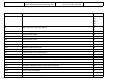


PE54.30-S-2000-60VA Legend of wiring diagram for instrument cluster
(CLUS) / display instruments / warning devices
MODEL 639.601 /603 /605 /701 /703
/705 /711 /713 /811 /813 /815
Code Designation Coordinates
A1 Instrument cluster 2A
10A
19A
28A
35A
39A
A2 Radio / Sound 10 / Sound 40 / Audio 10 39L
42L
A56 Modular tachograph 22L
B6 Speed inductive sensor 35L
B6/4 Speed inductive sensor 30L
B6/6 Speed inductive sensor 18L
K40/9 Fuse and relay block 9L
N66/4 Rear conversation unit control unit 51L
N123 Hands-free system control unit 48L
U10 Valid for Sound 40 Pro radio 42J
U15 Valid for screen in rear and DVD player 51J
U16 Valid for screen in rear, DVD player and TV tuner 51J
U51 Valid for telephone preinstallation 48J
U905 Valid without ABS/ASR and with 1 day/2 driver tachograph 16D
U906 Valid for odometer preinstallation and without 1 day/2 driver tachograph 16E
U907 Valid without ABS/ASR and with 1 day/2 driver tachograph 20D
U908 Valid for odometer preinstallation and with 1 day/2 driver tachograph 20E
U909 Valid for radio preinstallation 45J
U910 Valid for radio Sound 10 with cassette drive 39J
U911 Valid for 1 day/2 driver tachograph and with automatic transmission 33G
Copyright DaimlerChrysler AG 03.12.2005 CD-Ausgabe G/11/05 . This WIS print-out will not be recorded by Modification services. Page 1