
Electrical Wiring Diagram


OV00.01-S-1901-03VA Use of wiring diagrams
The wiring diagrams are prepared as function diagrams or controla
Wiring diagrams
unit diagrams and are built up as follows:
The wiring diagrams are assigned to the familiar function groupsa
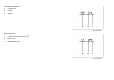
-Function diagrams
00-91. The systems are listed alphabetically with an indication of
The control units and electrical components belonging to the
the function group/ function subgroup in the "Search aid for all
function are shown as symbols. The functional connections are
wiring diagram groups"
realized by direct lines or by the data bus.
OV00.01-S-1901VA or A3 (paper version).
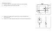
-Control unit diagrams
The wiring diagrams are filed in the respective function groupa
Control units are represented complete with all connected
arranged according to the PE number,
components. The feed of the control units appears first.
e.g.: PE07.16-S-2000VA
The wiring diagrams also contain linkages of possible versions and
PE07.16-S-2000IVB
functions.
To check the completeness of the volume the sequence of the
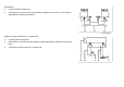
Linkages, recognizable as versions, are framed and provided with
wiring diagrams filed can be seen from the lists of contents of the
an abbreviated designation/ abbreviation.
respective function group. For supplements the wiring diagrams
The versions are designated with 1
should be filed as per the supplement sheet.
and 2
e.g.: PE00.19-P-1100VA Overview of wiring diagrams....
-------------------------------------------------------------------------------------
-----------------------------------------------------------------------------------
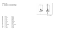
Notes on the accompanying documents for connectors/ terminala
blocks (B1)
Special equipment (SA) is specifically highlighted in the notes
column. For connectors, which are installed in special
equipment, the special equipment is specified in the notes
column in the row in front of the connector designation. For
connectors, which are installed as standard, special
equipment specification is noted directly at the respective jack
and/or connector.
The feed of the terminal blocks is shown by means of an
arrow pointing to the left, the outputs by means of arrows
pointing to the right. The grouping of the individual variants/
special equipment (SA) is highlighted by means of broken
lines. All outputs to components, which are installed as
standard, are listed up to the first broken line.