
User's Manual


Quantum 1000 Base Station User
Figure 41, d
emonstrates graphically how these elements are applied to an overall lightning design.
Please note that this is simply a generic diagram and that each individual installation may have its own
specific requirements which may differ from the diagram. The key
The main items will be outlined in more detail in the following sections.
Figure
3.2 Lightning Rod
The Lightning Rod must be welded to the mast
constructed of a steel pointed tip and is in general installed at the highest point of the tower. It operates to
intercept the downward moving lightning strike by launching an upward going attachment spark.
attachment is achieved, the bulk of the lightning current follows the ionized path. In this way, the lightning
rod diverts the lightning away from equipment on the tower.
If the lightning rod is not installed at the highest point on the tower, t
highest point (usually a radio) is the most likely attachment point.
A Class I lightning rod (air terminal) is 3/8
inch copper or 5/8-
inch aluminum. Con
(stranded or strips) and materials (aluminum or copper). Since most soils contain acid or alkaloid
compounds that react with aluminum, any aluminum used must not come in contact with the so
Lightning rods (air terminals) 24 inches or higher should be used.
Quantum 1000 Base Station User
Guide
Rev 1.1, Page
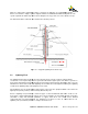
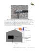
emonstrates graphically how these elements are applied to an overall lightning design.
Please note that this is simply a generic diagram and that each individual installation may have its own
specific requirements which may differ from the diagram. The key
point to note is the overall concept.
The main items will be outlined in more detail in the following sections.
Figure
41 - A Typical Lightning Protection Design
The Lightning Rod must be welded to the mast
structure and to a down conductor. This should be
constructed of a steel pointed tip and is in general installed at the highest point of the tower. It operates to
intercept the downward moving lightning strike by launching an upward going attachment spark.
attachment is achieved, the bulk of the lightning current follows the ionized path. In this way, the lightning
rod diverts the lightning away from equipment on the tower.
If the lightning rod is not installed at the highest point on the tower, t
he equipment that is connected to the
highest point (usually a radio) is the most likely attachment point.
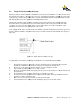
A Class I lightning rod (air terminal) is 3/8
-inch copper or 1/2-
inch aluminum, while Class II calls for 1/2
inch aluminum. Con
ductor sizes vary accordingly, also depending on their composition
(stranded or strips) and materials (aluminum or copper). Since most soils contain acid or alkaloid
compounds that react with aluminum, any aluminum used must not come in contact with the so
Lightning rods (air terminals) 24 inches or higher should be used.
Rev 1.1, Page
39 of 70
emonstrates graphically how these elements are applied to an overall lightning design.
Please note that this is simply a generic diagram and that each individual installation may have its own
point to note is the overall concept.
structure and to a down conductor. This should be
constructed of a steel pointed tip and is in general installed at the highest point of the tower. It operates to
intercept the downward moving lightning strike by launching an upward going attachment spark.
Once the
attachment is achieved, the bulk of the lightning current follows the ionized path. In this way, the lightning
he equipment that is connected to the
inch aluminum, while Class II calls for 1/2
-
ductor sizes vary accordingly, also depending on their composition
(stranded or strips) and materials (aluminum or copper). Since most soils contain acid or alkaloid
compounds that react with aluminum, any aluminum used must not come in contact with the so
il.