
User's Manual Part 1
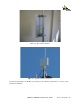

Quantum 1000 Base Station User
Figure
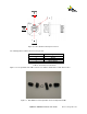
The following table 2 indicates the connector pin
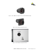
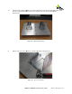
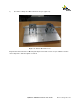
Figure 17
is an expanded view of the connector onto which is attached the actual cable of wires.
Figure 17 -
Base Station Power Input Cable Connector Expanded View
Quantum 1000 Base Station User
Guide
Rev 1.1, Page
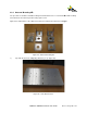
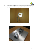
16 - Base Station Power Input Connector
The following table 2 indicates the connector pin
-outs.
Pin #
Signal
1 -48V DC
2 -48V DC
3 48v DC Return
4 48v DC Return
Table 2 – Power Pin-out connections
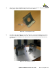
is an expanded view of the connector onto which is attached the actual cable of wires.
Base Station Power Input Cable Connector Expanded View
Rev 1.1, Page
22 of 70
is an expanded view of the connector onto which is attached the actual cable of wires.
Base Station Power Input Cable Connector Expanded View