
User's Manual

Quantum 1000 Base Station User
• E-
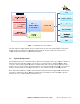
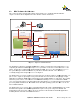
NET 2: This Gigabit Ethernet port provides an out
this port can be used for d
aisy
device such as a web Camera
aggregated and passed through the backhauling connector
NOTE:
DO NOT POWER ON THE
BASE STATION OR REMO
TWO TRANSMITTING ANT
ENNA PORTS (ANT 1 AN
SUITABLE RF LOAD OR
AN ANTENNA. A FAILUR
RESULT IN INTER
NAL DAMAGE TO THE BA
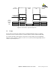
Figure
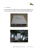
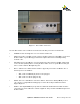
Connect the two transmitting ports (ANT 1 and ANT 2) to the two outer most elements of the actual
antenna thus ensuring that the transmission paths are as far apart as possible on the 4 available antenna
ports.
It is also important that while the base s
antenna ports remain terminated. Removal of the transmitter load while operating at high output powers is
not recommended and may result in damage to the base station.
2.6 Power
The Base Station DC power requirements is such that the external DC source needs to be capable of
delivering up to 4
Amps of current at
48VDC.
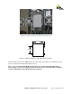
PureWave provides the power connector to the Base S
Installation kit (figure 13).
The "Tyco
" power connector that is used on the Base Station will
Remember to take account of the voltage drop when running long power cable runs.
AWG, for a cable length of 1
00 feet, a nominal 48VDC supply delivering into a
voltage drop of 2.7 volts.
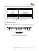
Please ensure that the DC power source is powered off and solder the
and 2.
Solder the 48 VDC Return wires to pins
Quantum 1000 Base Station User
Guide
Rev 1.1, Page
NET 2: This Gigabit Ethernet port provides an out
-of-
band management interf
aisy
chaining
to another base station or to connect to an external
device such as a web Camera
. T
he traffic coming from the daisy chain connector shall be
aggregated and passed through the backhauling connector
.
BASE STATION OR REMO
VE THE BASE STATION
POWER UNLESS THE
ENNA PORTS (ANT 1 AN
D ANT 2) ARE EITHER
TERMINATED BY A
AN ANTENNA. A FAILUR
E TO ENSURE THIS, AT
ALL TIMES, COULD
NAL DAMAGE TO THE BA
SE STATION (FIGURE 12).
Figure
12 - Base Station Connected
Connect the two transmitting ports (ANT 1 and ANT 2) to the two outer most elements of the actual
antenna thus ensuring that the transmission paths are as far apart as possible on the 4 available antenna
It is also important that while the base s
tation is operating at maximum power levels, the transmitting
antenna ports remain terminated. Removal of the transmitter load while operating at high output powers is
not recommended and may result in damage to the base station.
The Base Station DC power requirements is such that the external DC source needs to be capable of
Amps of current at
-48 VDC.
The Base Station nominally runs at approx 2 Amps at
PureWave provides the power connector to the Base S
tation (Tyco P/N
796094
" power connector that is used on the Base Station will
accommodate 14 to
18
Remember to take account of the voltage drop when running long power cable runs.
For
00 feet, a nominal 48VDC supply delivering into a
2
A load will lead to a
Please ensure that the DC power source is powered off and solder the
-
48 VDC wires to connector pins 1
Solder the 48 VDC Return wires to pins
3 and 4 (figures 14 to 16).
Rev 1.1, Page
20 of 70
band management interf
ace. In addition,
to another base station or to connect to an external
he traffic coming from the daisy chain connector shall be
POWER UNLESS THE
TERMINATED BY A
ALL TIMES, COULD
Connect the two transmitting ports (ANT 1 and ANT 2) to the two outer most elements of the actual
antenna thus ensuring that the transmission paths are as far apart as possible on the 4 available antenna
tation is operating at maximum power levels, the transmitting
antenna ports remain terminated. Removal of the transmitter load while operating at high output powers is
The Base Station DC power requirements is such that the external DC source needs to be capable of
The Base Station nominally runs at approx 2 Amps at
-
796094
-2) as part of the
18
gauge wire.
For
example, for 18
A load will lead to a
48 VDC wires to connector pins 1