
User's Manual


Quantum 1000 Base Station User
No software pre-configu
ration is required and all that is needed is to connect the Base Station to a GPS.
When the Base Station detects that a 1 pps GPS signal is present then it will synchronize its TDD gate to
the GPS and if it does not detect a 1 pps GPS signal then it will s
In the event that there are co-
located multiple Base Stations, it is important to synchronize all the Base
Station to a 1 pps GPS such that this will co
concurrently.
This is especially important if neighboring Base Stations are set to operate on overlapping
or identical frequency channels.
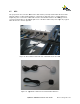
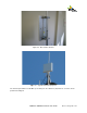
2.8 Antenna
A low-
loss, coaxial cable has to be connected to each of the N
back of the antenna panel and the respective antenna port on the base of the Base Station Sector. The
co-
axial cable must be capable of propagating the rel
recommended to use any high-
performance, low
Technologies P/N CA3N100 or Times Microwave LMR 400).The order of antenna connections is
unimportant.
The important consider
ation is the length of the co
and thus effective range of the system. In the case that the Base Station unit is installed outdoors and
close to the antenna, then the co-
axial cable runs can be kept
Base Station unit is installed indoors with long cable runs up the tower to the antennas then the amount of
signal loss will need to be calculated to ensure that adequate range will still be achieved. As an example,
a Times Microwave LMR400 cable has an attenuation loss of 6.8dB per 100 feet at a frequency of
2.5GHz.
For your information, the procedure to install co
Note:
It is strongly recommended that appropriate lightn
installed (refer to section 3).
Please ensure that appropriate weather protection is applied to all
outdoor N-
type coaxial connections.
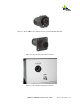
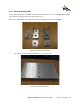
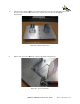
One antenna panel is used for each Base Station. The antenna panel is populated with a number of
directional patch-
element strips. All elements are enclosed within a single radome and common, rear
mounting plate. Access to each element (antenna) is provide
connector. Thus, for a 4-
element antenna panel configuration there are a total of 4 exposed RF
connectors protruding from the rear mounting plate (refer to figures
The specifications for the 2.5GHz a
nd the 3.65GHz antenna’s are detailed in Appendix A.
Quantum 1000 Base Station User
Guide
Rev 1.1, Page
ration is required and all that is needed is to connect the Base Station to a GPS.
When the Base Station detects that a 1 pps GPS signal is present then it will synchronize its TDD gate to
the GPS and if it does not detect a 1 pps GPS signal then it will s
ynchronize to its own internal source.
located multiple Base Stations, it is important to synchronize all the Base
Station to a 1 pps GPS such that this will co
-
ordinate all Base Station to transmit and receive
This is especially important if neighboring Base Stations are set to operate on overlapping
loss, coaxial cable has to be connected to each of the N
-
type female connectors located on the
back of the antenna panel and the respective antenna port on the base of the Base Station Sector. The
axial cable must be capable of propagating the rel
evant RF frequency and therefore it is
performance, low
-loss 400-
series coaxial cable (i.e. Hyperlink
Technologies P/N CA3N100 or Times Microwave LMR 400).The order of antenna connections is
ation is the length of the co
-
axial cable as this will affect the amount of signal loss
and thus effective range of the system. In the case that the Base Station unit is installed outdoors and
axial cable runs can be kept
short and thus loss is minimized. If the
Base Station unit is installed indoors with long cable runs up the tower to the antennas then the amount of
signal loss will need to be calculated to ensure that adequate range will still be achieved. As an example,
a Times Microwave LMR400 cable has an attenuation loss of 6.8dB per 100 feet at a frequency of
For your information, the procedure to install co
-
axial connectors is provided in Appendix A.
It is strongly recommended that appropriate lightn
ing surge protection devices are
Please ensure that appropriate weather protection is applied to all
type coaxial connections.
One antenna panel is used for each Base Station. The antenna panel is populated with a number of
element strips. All elements are enclosed within a single radome and common, rear
mounting plate. Access to each element (antenna) is provide
d by a dedicated N-
type female coaxial RF
element antenna panel configuration there are a total of 4 exposed RF
connectors protruding from the rear mounting plate (refer to figures
20 and 21).
nd the 3.65GHz antenna’s are detailed in Appendix A.
Rev 1.1, Page
24 of 70
ration is required and all that is needed is to connect the Base Station to a GPS.
When the Base Station detects that a 1 pps GPS signal is present then it will synchronize its TDD gate to
ynchronize to its own internal source.
located multiple Base Stations, it is important to synchronize all the Base
ordinate all Base Station to transmit and receive
This is especially important if neighboring Base Stations are set to operate on overlapping
type female connectors located on the
back of the antenna panel and the respective antenna port on the base of the Base Station Sector. The
evant RF frequency and therefore it is
series coaxial cable (i.e. Hyperlink
Technologies P/N CA3N100 or Times Microwave LMR 400).The order of antenna connections is
axial cable as this will affect the amount of signal loss
and thus effective range of the system. In the case that the Base Station unit is installed outdoors and
short and thus loss is minimized. If the
Base Station unit is installed indoors with long cable runs up the tower to the antennas then the amount of
signal loss will need to be calculated to ensure that adequate range will still be achieved. As an example,
a Times Microwave LMR400 cable has an attenuation loss of 6.8dB per 100 feet at a frequency of
axial connectors is provided in Appendix A.
ing surge protection devices are
Please ensure that appropriate weather protection is applied to all
One antenna panel is used for each Base Station. The antenna panel is populated with a number of
element strips. All elements are enclosed within a single radome and common, rear
type female coaxial RF
element antenna panel configuration there are a total of 4 exposed RF
nd the 3.65GHz antenna’s are detailed in Appendix A.