
User's Guide


Quantum 2200 Installation Guide v2.1
Page 13
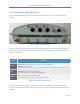
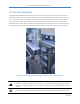
2.3 Connectors and Indicators
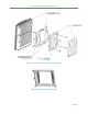
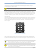
Figure 3 shows the bottom panel of the base station, where all the connectors and indicators are
located.
Figure 3: Base Station Connectors
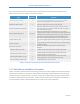
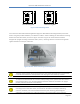
The base station connector panel contains 3 high-intensity LEDs that are intended to be viewable from
the ground for quick confirmation of the operational state of the base station. Table 2 describes the
function of each LED.
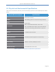
LED
Function
STATUS
Green - BS is up and running normally. No faults detected.
Blinking Red – System booting up, or system is temporarily down.
Solid Red - Fault detected.
Off – LEDs disabled or Power is off. Fault detected if POWER LED is Green, but STATUS LED is Off.
LINK
Solid Green – Connected to an Ethernet switch.
Blinking Green – Ethernet packet activity.
Off – LEDs disabled or no Ethernet activity detected.
POWER
Green – Power is being supplied to the BS.
Off – LEDs disabled or no power is being supplied to the BS.
Table 2: Base Station LED Description
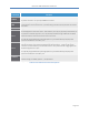
The function of each base station connector/port is described in Table 3. Note that every present
connector must be terminated according to the instructions in this guide to ensure proper base station
operation.