
User's Guide


Quantum 2200 Installation Guide v2.1
Page 17
If you have ordered the pole mounting kit then it was shipped in the same box as the base station.
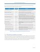
Please locate the kit and compare its contents to Table 4.
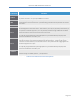
Item
Quantity
Purpose
a) Front Pole Mount Plate
1
Grips pole along with back pole mount plate (b). The base
station mounting bracket also connects to this piece.
b) Back Pole Mount Plate
1
Grips pole along with front pole mount plate (a).
c) Base Station Mounting Bracket
1
Attaches to base station mounting holes, as well as to front
pole mount plate (a). A built-in handle facilitates carrying the
base station when attached.
d) Carriage Bolt SAE 3/8-16
Up to 12
Selection of carriage bolts ranging from 6” to 10”, fully or
partially threaded. Select a set of 4 that are appropriate to the
installation, and use with push nut (e), hex nut (g), and washer
(h) to fasten front (a) and back (b) mounting plates to pole.
e) Nylon Pushnut, 3/8
4
Slide onto carriage bolt (d) to prevent it from slipping out of
front mounting plate (a) while fastening hex nut (g) and washer
(h).
f) Nylon Tie Wrap
2
Use to temporarily affix mounting hardware to pole during the
installation process.
g) Hex Nut, SAE 3/8-16
4
Use with carriage bolts (d) and split lock washers (h) as
described.
h) Split Lock Washer, SAE 38
4
Use with carriage bolts (d) and hex nuts(g) as described.
i) Hex Bolt, Metric M8 -1.25 X 16
6
Use with M8 split lock washers (k) to fasten base station
mounting bracket (c) to base station.
j) Hex Bolt, Metric M8 -1.25 X 25
4
Use with M8 split lock washers (k) to fasten base station
mounting bracket (c) to front pole mount plate (a).
k) Split Lock Washer, Metric M8
10
Use with M8 bolts (i, j) as described.
Table 4: PureWave Quantum Base Station Pole Mount Kit Contents
3.2.1 Pole Mount Installation Procedure
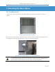
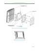
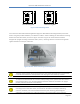
Figure 7 illustrates how the entire pole-mounting mechanism connects together and to the base station.
The pole mount mechanism consists of a base station bracket (Figure 8) that attaches to the mounting
points on the back of the base station, and a pair of pole-mount plates (Figure 9) that grip the pole and
to which the base station bracket attaches. Table 4 indicates where each included piece of hardware is
to be used and should be strictly followed to ensure a secure and proper installation.