Contents Before driving Introduction 2 Instrumentation 3 Controls and features Seating and safety restraints 19 110 Starting and driving Starting 152 Driving 157 Roadside emergencies 171 Servicing Maintenance and care 191 Capacities and specifications 235 Customer assistance 241 Reporting safety defects 254 Index 255 All rights reserved.
Introduction ICONS Indicates a safety alert. Read the following section on Warnings. Indicates vehicle information related to recycling and other environmental concerns will follow. Correct vehicle usage and the authorized disposal of waste cleaning and lubrication materials are significant steps towards protecting the environment. Indicates a message regarding child safety restraints. Refer to Seating and safety restraints for more information.
Instrumentation 3
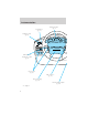
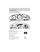
Instrumentation Instrument cluster (pg. 6) Panel dimmer (pg. 19) Headlamp control (pg. 19) 3 2 AUTO 1 1 0 OFF AUTO 2 4 40 5 20 7 50 60 60 30 6 40 80 100 70 120 140 F 80 90 H N O R M A L 1/2 E C TEMP FUEL 0 0 DIM PUSH INTERIOR RES ACCEL VOL CANCEL NEXT VOL COAST SET CRUISE OFF Turn signal and wiper/washer control (pg. 86) Speed control (pg. 85) Audio controls * (pg. 85) Driver side air bag (pg. 131) Anti-theft indicator light* (pg.
Instrumentation Gearshift (including overdrive button) (pg. 161) Rear wiper/washer (pg. 87) Hazard flasher (pg. 171) Rear defroster (pg. 39) VE DRI ON ER OV OFF/ Auxiliary power point (pg. 80) HAZAR D RR WA SH RR WIP ER RR DEF OG SECUR ITY Electronic sound system (pg. 40) VOL - PUSH ON AM FM DC 12V CLK BASS TREB BAL FADE CD SEEK SCAN TUNE SIDE 1 - 2 EJ REW DISCS CD CD 1 2 1 TAPE AMS 3 4 FF COMP SHUFFLE 5 6 Climate control system (pg.
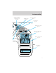
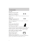
Instrumentation WARNING LIGHTS AND CHIMES Standard analog instrument cluster 40 4 3 5 30 2 6 1 0 7 RPMx1000 50 60 100 80 40 20 F 80 140 N O R M A L 1/2 E 90 10 0 0 0 000000 0 0 MPH R N D 2 1 P ! P BRAKE C TEMP FUEL 100 km/h FUEL DOOR AIR BAG H 160 20 8 70 120 60 UNLEADED FUEL ONLY SERVICE ENGINE SOON CRUISE O/D OFF Optional electronic instrument cluster CRUISE OUTSIDE TEMP INST ECONOMY AVG.
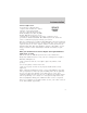
Instrumentation Safety belt Momentarily illuminates when the ignition is turned to the ON position to remind you to fasten your safety belts. For more information, refer to the Seating and safety restraints chapter. Brake system warning Momentarily illuminates when the ! P ignition is turned to the ON position. Also illuminates if the BRAKE parking brake is engaged. If the brake warning lamp does not illuminate at these times, seek service immediately.
Instrumentation Turn signal Illuminates when the left or right turn signal or the hazard lights are turned on. If one or both of the indicators stay on continuously or flash faster, check for a burned-out turn signal bulb. Refer to Exterior bulbs in the Maintenance and care chapter. Speed control This light comes on when either the CRUISE COAST/SET or RES/ACCEL controls are pressed. It turns off when the cruise cancel control is pressed, the brake is applied or the ignition is turned to the OFF position.
Instrumentation Service engine soon Your vehicle is equipped with a SERVICE computer that monitors the engine’s ENGINE emission control system. This SOON system is commonly known as the On Board Diagnostics System (OBD II). The OBD II system protects the environment by ensuring that your vehicle continues to meet government emission standards. The OBD II system also assists the service technician in properly servicing your vehicle.
Instrumentation Light is blinking: Engine misfire is occurring which could damage your catalytic converter. You should drive in a moderate fashion (avoid heavy acceleration and deceleration) and have your vehicle serviced at the first available opportunity. Under engine misfire conditions, excessive exhaust temperatures could damage the catalytic converter, the fuel system, interior floor coverings or other vehicle components, possibly causing a fire.
Instrumentation Headlamps on warning chime Sounds when the headlamps or parking lamps are on, the ignition is off (and the key is not in the ignition) and the driver’s door is opened.
Instrumentation • Standard analog instrument cluster 4 3 • Optional electronic instrument cluster 5 2 6 1 0 7 CRUISE 8 RPMx1000 5 4 3 6 7 8 2 MPH km/h km 1 X 1000 TRIP 1 TRIP 2 RPM 0 Speedometer Indicates the current vehicle speed.
Instrumentation Odometer Registers the total kilometers (miles) of the vehicle. • Standard analog instrument 0 0 cluster • Optional electronic instrument cluster CRUISE 3 0 0 0 0 4 5 6 7 8 2 MPH km/h km 1 X 1000 TRIP 1 TRIP 2 RPM 0 Refer to Electronic Message Center for information on how to switch the display from metric to English measurements. Trip odometer Registers the kilometers (miles) of individual journeys. • Standard analog instrument cluster To reset, depress the control.
Instrumentation empty indication, the amount of fuel that can be added will be less than the advertised capacity due to the reserve fuel. • Standard analog instrument F cluster E FUEL • Optional electronic instrument cluster F 1/2 E Engine coolant temperature gauge Indicates the temperature of the engine coolant. At normal operating temperature, the needle remains within the normal area (the area between the “H” and “C”). If it enters the red section, the engine is overheating.
Instrumentation • Optional electronic instrument cluster H N O R M A L C ELECTRONIC MESSAGE CENTER (IF EQUIPPED) The electronic message center only works when the ignition is in the ON position. The message center allows you to: • display the outside temperature. • change your gauges from english ˚F ˚C to metric units. MILES/GAL L/100 km MILES km • monitor the instantaneous fuel OUTSIDE TEMP economy. INST ECONOMY AVG ECONOMY • monitor the average fuel TO EMPTY economy.
Instrumentation • • • • OUTSIDE TEMP INST ECONOMY AVG ECONOMY TO EMPTY ˚F ˚C MILES/GAL L/100 km MILES km OUTSIDE TEMP INST ECONOMY AVG ECONOMY TO EMPTY RESET Press this control to reset the RESET ENG / MET TRIP / RST average fuel economy calculation. SELECT OD / TRIP ENG/MET Press this control to change your instrument cluster gauges from english to metric.
Instrumentation INST ECONOMY Press SELECT until the menu displays INST ECONOMY. This will display your fuel economy in ˚F ˚C MILES/GAL liters/100 km or miles/gallon based L/100 km MILES km on the type of traffic you are in. OUTSIDE TEMP INST ECONOMY Your vehicle must be moving to AVG ECONOMY TO EMPTY calculate instantaneous fuel economy. When your vehicle is not moving, this function shows 99.9 L/100km or 0.0 MILES/GAL. Instantaneous fuel economy cannot be reset.
Instrumentation 2. Select AVG ECONOMY. 3. Press the RESET control to clear the system memory. RESET ENG / MET TRIP / RST • Actual highway fuel economy is now displayed. This current SELECT OD / TRIP average measure will change as the speed control system changes the engine speed to maintain a constant vehicle speed. This is most noticeable in hilly environments. 4. Drive the vehicle at least 8 km (5 miles) with the speed control system engaged to display a stabilized average. 5.
Controls and features PANEL DIMMER CONTROL Use to adjust the brightness of the instrument panel. • Push and hold top of control to brighten. • Push and hold bottom of control to dim. HEADLAMP CONTROL Rotate the headlamp control clockwise to the first position to turn on the parking lamps. Rotate clockwise to the second position to also turn on the headlamps. Push the control to turn on the interior lamps. Push control again to turn off the interior lamps.
Controls and features High beams Push forward to activate. Pull toward you to deactivate. HI LO F S OFF Flash to pass Pull toward you to activate and release to deactivate. HI LO F S OFF AUTOLAMP CONTROL (IF EQUIPPED) The autolamp system provides light OFF AUTO sensitive automatic on-off control of 1 the exterior lights normally AUTO controlled by the headlamp control. 2 The autolamp system also keeps the lights on for a preselected period of time after the ignition switch is turned to OFF.
Controls and features CLIMATE CONTROL SYSTEM Manual heating and air conditioning system 1 OFF 2 3 4 CLIMATE CONTROL SYSTEM MAX A/C A/C Fan speed control Controls the volume of air circulated in the vehicle. 1 2 3 4 Temperature control Controls the temperature of the airflow inside the vehicle. Mode selector control Controls the direction of the airflow to the inside of the vehicle.
Controls and features The air conditioning operates in MAX A/C and when the A/C control is depressed. However, the air conditioning will only function if the outside temperature is about 4°C (40°F) or higher. Since the air conditioner removes considerable moisture from the air during operation, it is normal if clear water drips on the ground under the air conditioner drain while the system is working and even after you have stopped the vehicle.
Controls and features and air conditioning capabilities are provided in this mode. For added customer comfort, when the temperature control knob is anywhere in between the full hot and full cold positions, the air distributed through the front and rear floor ducts will be slightly warmer than the air sent to the windshield defroster ducts. If the outside temperature is about 4°C (40°F) or higher, the air conditioner will automatically dehumidify the air to reduce fogging.
Controls and features Rear seat heating Rear seat heating is provided through the floor ducts located under the front seats. Airflow and temperature to the rear seating are regulated by the main climate control system. OFF REAR A/C 1 2 3 4 A/C The rear passenger compartment air conditioning system (if equipped) should be set to OFF, if rear heating is desired. Operating tips • In humid weather, select before driving. This will reduce fogging on your windshield.
Controls and features • Remove any snow, ice or leaves from the air intake area (at the bottom of the windshield under the hood). • If your vehicle has been parked with the windows closed during hot weather, the air conditioner will do a much faster job of cooling if you drive for two or three minutes with the windows open. This will force most of the hot, stale air out of the vehicle. Then operate your air conditioner as you would normally.
Controls and features The rear A/C fan speed control allows the rear passengers to control the volume of air that is distributed from the rear registers. 0 1 4 3 REAR A/C 2 The rear seat A/C system is controlled from the main climate control system on the instrument panel.
Controls and features Turning the Rear A/C on 1 OFF 2 3 MAX A/C 4 OFF REAR A/C 1 2 3 4 A/C 1. Set the main climate control rear fan control to Rear A/C, set the mode selector in any position (other than OFF), and depress the A/C control. 2. Set the fan speed on the Rear A/C fan control to a number between 1–4. REAR A/C 1 4 3 2 Front seat air flow regulation of the rear fan Set the main climate control rear fan control to a number between 1–4.
Controls and features Turning the Rear A/C off: OFF REAR A/C 1 2 3 4 A/C To turn the Rear A/C off, turn the Rear Fan Control on the main climate control system to OFF, or OFF REAR A/C 1 2 3 4 A/C 0 1 4 3 REAR A/C 2 turn the Rear Fan Control on the main climate control system to Rear A/C and turn the Rear A/C Fan Control to 0. For maximum cooling for the front seat passengers, set the rear fan switch to the OFF (0) position.
Controls and features Electronic Automatic Temperature Control (EATC) system (if equipped) A/C OFF HI MAX OFF REAR 1 A/C TEMP AUTOMATIC 2 3 4 LO The EATC system will maintain a selected temperature and automatically control airflow. You can override automatic operation with any of the override controls or the fan speed control. Turning the EATC on A/C OFF HI MAX TEMP AUTOMATIC OFF REAR 1 A/C 2 3 4 LO Press AUTOMATIC, any of the override controls or the fan speed control.
Controls and features Turning the EATC off Press OFF. OFF OFF REAR 1 A/C TEMP AUTOMATIC Automatic operation Press AUTOMATIC and select the desired temperature. The selected temperature and the word AUTO will appear in the display window. The EATC system will either heat or cool to achieve the selected temperature. The system will automatically determine fan speed, airflow location and if outside air or recirculated air is required. Fan speed remains automatic unless the fan speed control is turned.
Controls and features To control the temperature, select any temperature between 15°C (60°F) and 32°C (90°F) by pressing the temperature controls. OFF TEMP AUTOMATIC OFF REAR 1 A/C For continuous maximum cooling, push the temperature control until 15°C (60°F) is shown in the display window. The EATC will continue maximum cooling (disregarding the displayed temperature) until a warmer temperature is selected by pressing the temperature controls.
Controls and features Fan speed ( ) When AUTOMATIC is pressed, fan speed is adjusted automatically for existing conditions. You can override fan speed at any time. To control fan speed manually, use the thumbwheel to cancel automatic fan speed operation. Rotate the thumbwheel up for higher fan speed or down for lower fan speed. The display will show manual fan operation. HI A/C MAX 1 2 3 4 LO to indicate ˚F AUTO To return to automatic fan operation, press AUTOMATIC.
Controls and features Since the air conditioner removes considerable moisture from the air during operation, it is normal if clear water drips on the ground under the air conditioner drain while the system is working and even after you have stopped the vehicle. Under normal conditions, your vehicle’s climate control system should be left in any position other than MAX or OFF when the vehicle is parked. This allows the vehicle to “breathe” through the outside air inlet duct.
Controls and features • MAX A/C-Uses recirculated air to cool the vehicle. MAX A/C is noisier than A/C A/C but more economical and will cool the inside of the vehicle faster. After pressing the MAX control, both the MAX and A/C A/C indicators will light and the airflow will be from the instrument panel registers. In this mode, the air conditioning will automatically engage if the outside temperature is about 4°C (40°F) or higher.
Controls and features Rear seat heating Rear seat heating is provided through the floor ducts located under the front seats. Airflow and temperature to the rear seating are regulated by the main climate control system. OFF REAR A/C 1 2 3 4 A/C The rear passenger compartment air conditioning system (if equipped) should be set to OFF, if rear heating is desired. Operating tips • In humid weather, select (Defrost) before driving. This will reduce fogging on your windshield.
Controls and features • Remove any snow, ice or leaves from the air intake area (at the bottom of the windshield). • If your vehicle has been parked with the windows closed during hot weather, the air conditioner will do a much faster job of cooling if you drive for two or three minutes with the windows open. This will force most of the hot, stale air out of the vehicle. Then operate the air conditioner as you would normally.
Controls and features The rear A/C fan speed control allows rear passengers to control the volume of air that is distributed from the rear registers. The rear A/C system is controlled from the main climate control system on the instrument panel. The rear seat A/C system is controlled from the main climate control system on the instrument panel.
Controls and features Turning the Rear A/C on 1. Set the main climate control rear fan control to Rear A/C, set the mode selector in any position (other than OFF), and depress the A/C control. 2. Set the fan speed on the Rear A/C fan control to a number between 1–4. REAR A/C 1 4 3 2 Front seat air flow regulation of the rear fan Set the main climate control rear fan control to a number between 1–4. This numerical settingwill take control of the airflow from the rear A/C fan control.
Controls and features OFF REAR A/C 1 2 3 4 A/C 0 1 4 3 REAR A/C 2 turn the Rear Fan Control on the main climate control system to Rear A/C and turn the Rear A/C Fan Control to 0. For maximum cooling for the front seat passengers, set the rear fan switch to the OFF (0) position. Please note that the rear passenger air conditioning system is designed for air conditioning purposes only, and does not heat the rear compartment. Rear compartment heating is provided by the underseat ducts.
Controls and features The ignition must be in the ON position to operate the rear window defroster. The defroster turns off automatically after 15 minutes or when the ignition is turned to the OFF position. To manually turn off the defroster before 15 minutes have passed, push the control again.
Controls and features Turn the control to raise or lower volume. VOL - PUSH ON If the volume is set above a certain level and the ignition is turned off, the volume will come back on at a “nominal” listening level when the ignition switch is turned back on. AM/FM select The AM/FM select control works in radio, tape and CD changer modes (if equipped). AM FM CD AM/FM select in radio mode This control allows you to select AM or FM frequency bands.
Controls and features Tune adjust in radio mode • Press to move to the next SEEK frequency down the band (whether or not a listenable TUNE station is located there). Hold the DISCS control to move through the frequencies quickly. • Press to move to the next frequency up the band (whether or not a listenable station is located there). Hold for quick movement. Tune adjust for CD changer (if equipped) • Press to select the previous SEEK disc in the CD changer.
Controls and features • Press to seek forward to the next track of the current disc. After the last track has been completed, the first track of the current disc will automatically replay. Scan function The scan function works in radio or CD changer mode (if equipped). SCAN Scan function in radio mode Press the SCAN control to hear a brief sampling of all listenable stations on the frequency band. Press the SCAN control again to stop the scan mode.
Controls and features Bass adjust The bass adjust control allows you to increase or decrease the audio system’s bass output. BASS Treble adjust The treble adjust control allows you to increase or decrease the audio system’s treble output. TREB Speaker balance adjust Speaker sound distribution can be adjusted between the right and left speakers. BAL Speaker fade adjust Speaker sound can be adjusted between the front and rear speakers.
Controls and features Tape select • To enter tape mode while in radio or CD changer mode, press the TAPE control. • If no tape is found, NO TAPE appears in the display. CLK TAPE AMS Automatic Music Search The Automatic Music Search feature allows you to quickly locate the CLK beginning of the tape selection being played or to skip to the next selection. TAPE AMS To activate the feature, momentarily depress the TAPE AMS button.
Controls and features Press the 1–2/FF control to stop rewinding the tape. SIDE REW 1-2 FF To rewind in CD changer mode, press the CD control (preset 1). Press the control again to deactivate rewind mode. CD 1 Fast forward The fast forward control works in tape and CD changer modes. To fast forward in tape mode, press SIDE 1 - 2 the 1–2/FF control. Tape direction will automatically REW FF reverse when the end of the tape is reached.
Controls and features The shuffle feature continues to the next disc after all tracks are played. Press the SHUFFLE control to start this feature. Random order play will continue until the SHUFFLE control is pressed again. Tape direction select Press SIDE and 1–2 at the same time to play the alternate side of a tape. Eject function Press the control to stop and eject a tape. SIDE REW 1-2 FF EJ DolbyT noise reduction Dolbyt noise reduction operates only in tape mode.
Controls and features • • to decrease hours and to increase hours. SEEK SEEK TUNE TUNE To set the minute, press and hold the CLK control and press the TUNE control: CLK TAPE AMS • • to decrease minutes and to increase minutes. SEEK SEEK TUNE TUNE The CLK control will allow you to switch between media display mode (radio station, stereo information, etc.) and clock display mode (time).
Controls and features Rear seat controls (if equipped) The Rear Seat Controls (RSC) allow the rear seat passengers to operate the radio, tape, or CD changer (if equipped). CD 1 VOLUME CD 2 3 4 MEDIA SEEK MEM COMP SHUFFLE 5 6 To turn on the rear seat controls, press the memory preset controls 3 will appear in the radio display. and 5 at the same time. The Pressing 3 and 5 at the same time again will turn the rear seat controls off. Adjusting the volume Press the + control to increase volume.
Controls and features Using headphones Plug a 3.6 mm headphone (not VOLUME included) into either one of the two jacks. Press the / control to operate the headphones. The speakers will cut out once the speaker on/off control is pressed. Press the / deactivate headphones. Media select Push the MEDIA control to toggle between AM, FM1, FM2, tape, or CD changer (if equipped).
Controls and features Premium AM/FM Cassette (CD changer compatible) BASS BAL SEL TREB VOL PUSH ON CD EJ TAPE AM FM TUNE SEEK MUTE REW FF SIDE 1.2 1 2 3 RDS / CLK SCAN 4 FADE AUTO COMP SHUFF 5 6 Your audio system is equipped with selective lighting, a unique lighting strategy. This lighting feature is operable when the headlamps are illuminated. During the operation of any selected mode, lighting for the individual function controls will either illuminate or turn off.
Controls and features Turn the control to raise or lower volume. VOL PUSH ON If the volume is set above a certain level and the ignition is turned off, the volume will come back on at a “nominal” listening level when the ignition switch is turned back on. AM/FM select The AM/FM select control works in radio, tape and CD changer modes (if equipped). AM FM AM/FM select in radio mode This control allows you to select AM or FM frequency bands.
Controls and features disc unless the CD changer is in shuffle mode.) Refer to Shuffle feature for more information. Hold the control to continue reversing through the disc. • Press to select the next disc in the CD changer. Hold the control to fast-forward through the remaining discs. Seek function The seek function control works in radio, tape or CD changer mode (if equipped). Seek function in radio mode • Press to find the next listenable station down the frequency band.
Controls and features Scan function in radio mode Press the SCAN control to hear a brief sampling of all listenable stations on the frequency band. Press the SCAN control again to stop the scan mode. Scan function in tape mode Press the SCAN control to hear a short sampling of all selections on the tape. (The tape scans in a forward direction. At the end of the tape’s first side, direction automatically reverses to the opposite side of the tape.) To stop on a particular selection, press the control again.
Controls and features Starting autoset memory preset 1. Select a frequency using the AM/FM select controls. 2. Press the AUTO control. 3. When the first six strong stations AUTO are filled, the station stored in memory preset control 1 will start playing. If there are less than six strong stations available on the frequency band, the remaining memory preset controls will all store the last strong station available.
Controls and features Speaker fade adjust Speaker sound can be adjusted between the front and rear speakers. BAL SEL FADE Tape/CD changer mode select (if equipped) • To begin tape play (with a tape loaded into the audio system) CD TAPE while in the radio or CD changer mode, press the TAPE control. Press the button during rewind or fast forward to stop the rewind or fast forward function and begin play. • To begin CD play (if CD[s] are loaded), press the CD control.
Controls and features • In CD changer mode, pressing the control for less than three seconds results in slow forward action. Pressing the control for more than three seconds results in fast forward action. Tape direction select Press SIDE 1–2 to play the alternate side of a tape. SIDE 1-2 3 Eject function Press the control to stop and eject a tape. EJ DolbyT noise reduction Dolbyt noise reduction operates only in tape mode. Dolbyt reduces the amount of hiss and static during 4 tape playback.
Controls and features Press the SHUFFLE control to start this feature. Random order play will continue until the SHUFFLE control is pressed again.
Controls and features • Use the SEL control to select the program type. With the feature on, use the SEEK or SCAN control to find the desired program type from the following selections: • Classic • Country • Info • Jazz • Oldies • R&B • Religious • Rock • Soft • Top 40 Show • With RDS activated, press the RDS control until SHOW is displayed. • Use the SEL control to select the program TYPE, station NAME or NONE (no text displayed).
Controls and features Use the SEL control to manually set the time. • Press to increase hours/minutes. to decrease • Press hours/minutes. SEL Mute mode Press the control to mute the MUTE playing media. Press the control again to return to the playing media. Rear seat controls (if equipped) The Rear Seat Controls (RSC) allow the rear seat passengers to operate the radio, tape, or CD changer (if equipped). REW FF SIDE 1.
Controls and features Adjusting the volume Press the + control to increase volume. VOLUME MEDIA MEM SEEK Press the — control to decrease volume. From the RSC, the speaker volume can not be set higher than the current volume radio setting. Once in headphone mode, the RSC volume controls will only change volume in the headphones to a desired level (muting the speakers will not mute the headphones). Turning the speakers on and off Press the control to turn all speakers on or off.
Controls and features Memory preset control Push the MEM control successively to allow rear sear passengers to scroll through the 6 memory presets in AM, FM1, or FM2. Push the MEM control in CD changer mode (if equipped) to advance to the next disc. VOLUME MEDIA SEEK MEM Seek function • Press to find the next listenable station down the VOLUME MEDIA MEM SEEK frequency band. • Press to find the next listenable station up the frequency band.
Controls and features Your audio system is equipped with selective lighting, a unique lighting strategy. This lighting feature is operable when the headlamps are illuminated. During the operation of any selected mode, lighting for the individual function controls will either illuminate or turn off. Those controls which have a function for the specific mode of operation selected will be lit, while the controls which have no function for that mode will be turned off.
Controls and features AM/FM select in radio mode This control allows you to select AM or FM frequency bands. Press the control to switch between AM, FM1 or FM2 memory preset stations. AM/FM select in tape mode Press this control to stop tape play and begin radio play. AM/FM select in CD mode Press this control to stop CD play and begin radio play. Tune adjust The tune control works in radio or CD mode.
Controls and features Seek function in radio mode • Press to find the next listenable station down the frequency band. • Press to find the next listenable station up the frequency band. SEEK SEEK TUNE TUNE Seek function in tape mode • Press to listen to the previous selection on the tape. to listen to the next selection on the tape. • Press Seek function for CD changer (if equipped) • Press to seek to the previous track of the current disc.
Controls and features Scan function in tape mode Press the SCAN control to hear a short sampling of all selections on the tape. (The tape scans in a forward direction. At the end of the tape’s first side, direction automatically reverses to the opposite side of the tape.) To stop on a particular selection, press the control again. Scan function in CD mode Press the SCAN control to hear a short sampling of all selections on the CD.
Controls and features Starting autoset memory preset 1. Select a frequency using the AM/FM select controls. 2. Press the AUTO control. AUTO 3. When the first six strong stations RDS are filled, the station stored in CLK memory preset control 1 will start playing. If there are less than six strong stations available on the frequency band, the remaining memory preset controls will all store the last strong station available.
Controls and features • • to decrease treble output and to increase treble output. SEL Speaker balance adjust Speaker sound distribution can be adjusted between the right and left speakers. Press the BAL control then press: • to shift sound to the left and to shift sound to the right. • Speaker fade adjust Speaker sound can be adjusted between the front and rear speakers. Press the FADE control then press: • to shift sound to the front and • to shift sound to the rear.
Controls and features Tape/CD/CD changer (if equipped) select • To begin tape play (with a tape loaded into the audio system) TAPE CD while in the radio or CD mode, press the TAPE control. Press the button during rewind or fast forward to stop the rewind or fast forward function. • To begin CD play (if CD(s) are loaded), press the CD control. TAPE CD The first track of the disc will begin playing. After that CD play will begin where it stopped last.
Controls and features Tape direction select Press SIDE 1–2 to play the alternate side of a tape. Eject function Press the control to stop and eject a tape. SIDE 1-2 3 EJ Press the control to stop and eject a CD. EJ Dolby noise reduction Dolby noise reduction reduces the amount of hiss and static during 4 tape playback. Press the control to activate (and deactivate) the noise reduction. Dolby noise reduction manufactured under license from Dolby Laboratories Licensing Corporation.
Controls and features Setting the clock Press the RDS/CLK control until SELECT HOUR is displayed and press: AUTO • • SEL to decrease hours and to increase hours. To set the minute, press the RDS/CLK control until SELECT MIN is displayed and press: • • to decrease minutes and to increase minutes.
Controls and features Press the RDS control. Use the SEL control to select ON or OFF to enable or disable the feature. SEL RDS traffic announcement When set ON, this traffic feature will AUTO interrupt tape or CD play to play a RDS traffic report broadcast from a FM CLK RDS station. To activate the traffic feature: • Press the RDS control until TRAFFIC is displayed. To see if any stations in your area are capable of broadcasting an RDS traffic alert, press SCAN or SEEK while TRAFFIC ON is displayed.
Controls and features • • • • • Jazz/R&B Religious Rock Soft Top 40 RDS show RDS sends information with the FM broadcast, including: station name, station type, and/or radio text. To view this information: • With the RDS menu enabled, press the RDS control until SHOW is displayed. • Use the SEL control to select TYPE, NAME, TEXT or NONE. When your radio is turned to a RDS station, RDS station TYPE, station NAME, or TEXT message will be displayed along with the frequency.
Controls and features REW FF SIDE 1-2 1 2 3 4 COMP SHUFFLE 5 6 To turn on the rear seat controls, press the memory preset controls 3 and 5 at the same time. The will appear in the radio display. Pressing 3 and 5 at the same time again will turn the rear seat controls off. If there is a discrepancy between the rear seat and the front audio controls, (i.e, both trying to listen to the same playing media), the front audio system will receive the desired selection.
Controls and features The rear speakers will cut out once the speaker on/off control is pressed. A soft audible sound may be heard from the rear speakers. The front speaker will remain playing for the front passengers. Press the / control again to deactivate headphones (Personal Audio System). Media select Push the MEDIA control to toggle between AM, FM1, FM2, tape, CD, or CD changer (if equipped).
Controls and features CD changer (if equipped) The CD changer is located in the center console of your vehicle. 1. Slide the door to access the CD changer magazine. 2. Press to eject the magazine. 3. Turn the magazine (A) over. 4. Using the disc holder release knob (C), pull the disc holder (B) out of the magazine.
Controls and features A If you pull too hard on the disc holder, the disc holder may come completely out of the magazine. If this happens, reinsert the disc holder back into the magazine while pressing on the lever (A). 5. Line up the CD with the groove of the disc holder. Ensure that the label on the CD faces downwards. 6. Press in on the disc holder until it locks securely into the magazine. If the disc holders are not fully locked into the magazine, the unit will not operate.
Controls and features The CD magazine may be inserted or ejected with the radio power on or off. ONLY use the magazine type supplied with the CD changer, other types will damage the unit. Keep the CD changer door closed. Coins and foreign objects will damage the CD player and void your audio system warranty. Do not insert any promotional (odd shaped or sized) discs into the CD changer as that jamming may occur.
Controls and features Cleaning cassette player Clean the tape player head with a cassette cleaning cartridge after ten to twelve hours of play in order to maintain the best sound and operation. Cassette and cassette player care • Use only cassettes that are 90 minutes long or less. • Do not expose tapes to direct sunlight, high humidity, extreme heat or extreme cold. Allow tapes that may have been exposed to extreme temperatures to reach a moderate temperature before playing.
Controls and features • Station overload. Weak signals are sometimes captured by stronger signals when you pass a broadcast tower. A stronger signal may temporarily overtake a weaker signal and play while the weak station frequency is displayed. The audio system automatically switches to single channel reception if it will improve the reception of a station normally received in stereo. Audio system warranties and service Refer to the “Warranty Guide” for audio system warranty information.
Controls and features POSITIONS OF THE IGNITION 1. OFF/LOCK, shuts off the engine 3 and all accessories/locks the steering wheel, gearshift lever and allows key 2 removal. 4 2. ACC, allows the electrical accessories such as the radio to operate while the engine is not running. 1 3. ON, all electrical circuits operational. Warning lights illuminated. Key position when driving. 4. START, cranks the engine. Release the key as soon as the engine starts. SPEED CONTROL To turn speed control on • Press CRUISE.
Controls and features To turn speed control off • Press OFF. CRUISE OFF Once speed control is switched off, the previously programmed set speed will be erased. To set a speed • Press COAST/SET. For speed control to operate, the speed control must be ON and the vehicle speed must be greater than 48 km/h (30 mph). RES ACCEL CANCEL COAST SET If you drive up or down a steep hill, your vehicle speed may vary momentarily slower or faster than the set speed. This is normal.
Controls and features To set a higher set speed • Press and hold RES/ACCEL. Release the control when the RES ACCEL desired vehicle speed is reached or • Press and release RES/ACCEL. CANCEL Each press will increase the set speed by 1.6 km/h (1 mph) or COAST • Accelerate with your accelerator SET pedal. When the desired vehicle speed is reached, press and release COAST/SET. You can accelerate with the accelerator pedal at any time during speed control usage.
Controls and features To disengage speed control • Depress the brake pedal. • Press CANCEL. Disengaging the speed control will not erase the previously programmed set speed. RES ACCEL CANCEL COAST SET • Press OFF. Pressing OFF will erase the previously programmed set speed.
Controls and features To return to a previously set speed • Press RES/ACCEL. For RES/ACCEL to operate, the vehicle speed must be faster than 48 km/h (30 mph). RES ACCEL CANCEL COAST SET Indicator light This light comes on in the CRUISE instrument cluster when either the COAST/SET or RES/ACCEL controls are pressed. It turns off when the speed control OFF control is pressed, the brake is applied or the ignition is turned to the OFF position.
Controls and features In any mode: • Press VOL up or down to adjust the volume. VOL NEXT VOL TURN SIGNAL CONTROL • Push down to activate the left turn signal. • Push up to activate the right turn signal. HI LO F S OFF WINDSHIELD WIPER/WASHER CONTROLS Rotate the windshield wiper control to the desired interval, low or high speed position. The bars of varying length are for intermittent wipers. When in this position rotate the control upward for fast intervals and downward for slow intervals.
Controls and features Rear window wiper and washer Press the wiper control to activate the rear wiper. Press again to turn off the wiper. The wiper operates at a pre-set interval. HAZARD RR WASH RR WIPER RR DEFOG SECURITY Press the washer control to activate the rear washer. The wiper will come on when the washer control is pressed, if it is not already on.
Controls and features Deactivating overdrive Press the Transmission Control Switch (TCS) located on the end of OVERDRIVE OFF/ON the gearshift lever. The O/D OFF indicator light will illuminate. The transaxle will operate in all gears except overdrive. To return to normal overdrive mode, press the Transmission Control Switch again. The O/D OFF indicator light will no longer be illuminated. When you shut off and re-start your vehicle, the transaxle will automatically return to normal D (Overdrive) mode.
Controls and features POWER WINDOWS • Press and hold the switch to open. • Pull up and hold the switch to close. Power vent windows (if equipped) Your vehicle may be equipped with rear power vent windows which are operated the same as the front power windows. One touch down • Press AUTO completely down and release quickly. The driver’s window will open fully. Depress again to stop window operation. AUTO AUTO AUTO The window lock feature allows only the driver to operate the power windows.
Controls and features Accessory delay With accessory delay, the window and moonroof switches may be used for up to 15 minutes after the ignition switch is turned to the OFF position or until either of the front doors are opened. POWER DOOR LOCKS Push control forward to unlock all doors and pull backward to lock all doors. Anti-lockout This feature prevents the front doors from being locked while the key is in the ignition and the driver’s door is open.
Controls and features Pull lock control out to engage the lock. Push control in to disengage childproof locks. POWER SIDE VIEW MIRRORS The ignition must be in ACC or ON position to adjust the power side view mirrors. To adjust your mirrors: 1. Select L to adjust the left mirror or R to adjust the right mirror.
Controls and features 2. Move the control in the direction you wish to tilt the mirror. MIRRORS L R 3. Return to the center position to lock mirrors in place. Heated outside mirrors (if equipped) Both mirrors are heated automatically to remove ice, mist and fog when the rear window defrost is activated. Do not remove ice from the mirrors with a scraper or attempt to readjust the mirror glass if it is frozen in place. These actions could cause damage to the glass and mirrors.
Controls and features HOMELINKT UNIVERSAL TRANSCEIVER WITH TRAVELNOTET (IF EQUIPPED) The HomeLinkt Universal Transceiver, located on the driver’s visor, provides a convenient way to replace up to three hand-held transmitters with a single built-in device. This feature will learn the radio frequency codes of most current transmitters to operate garage doors, entry gates, security systems, entry door locks, and home or office lighting.
Controls and features 4. The red light will flash slowly and then rapidly. Release both buttons when the red light flashes rapidly. 5. Follow steps 2 through 4 to program the remaining two buttons. If you do not successfully program the HomeLinkt Universal Transceiver after repeated attempts, refer to Rolling code programing which follows, or call toll-free customer assistance: 1–800–355–3515 or on the Internet at HomeLink.jci.com.
Controls and features • The hand-held transmitter appears to program the HomeLinkt Universal Transceiver but does not activate the device. • Press and hold the trained HomeLinkt button. The device has the rolling code feature if the indicator light flashes rapidly and then turns solid after 2 seconds. After completing the “Programming” functions, follow these steps to train a garage door opener with the rolling code feature: 1. Locate the training button on the garage door motor head unit.
Controls and features 1. Press and hold the desired HomeLinkt button. Do NOT release until step 4 has been completed. 2. When the indicator light begins to flash slowly (after 20 seconds), position the hand-held transmitter 5–14 cm (2 to 5 inches) away from the HomeLinkt surface. 3. Press and hold the hand-held transmitter button. 4. The HomeLinkt indicator light will flash, first slowly and then rapidly. When the indicator light begins to flash rapidly, release both buttons.
Controls and features To play a message: 1. Press and release the PLAY button to play the message. REC DEL PLAY 2. Press and hold the PLAY button to hear all the messages in consecutive order starting with the most recent. 3. If the PLAY button is pressed while a message is being listened to, TravelNote will skip to the beginning of the next message. 4. During all PLAY functions, the indicator light will be a solid green.
Controls and features Storage bin (if equipped) The storage compartment may be used to store small objects. Push in to open or close the cover. Installing a garage door opener (if equipped) The storage compartment can be converted to accommodate a variety of aftermarket garage door openers: • Remove the GARAGE control button from the storage compartment. • Place Velcroy on aftermarket transmitter opposite of actuator control. • Install the transmitter into storage compartment, control down.
Controls and features • Place the provided height adaptors on the back of the GARAGE control button as needed. • Place the GARAGE control button in the storage compartment. • Close cover and press the GARAGE control button to activate the transmitter. INTERIOR LAMPS Dome lamps The front dome lamp is located overhead between the driver and passenger seats. The dome lamp will stay on if the control is moved to the ON position.
Controls and features MOON ROOF (IF EQUIPPED) To operate the moon roof: • To open, press and hold the rear portion of the control. This will fully open the moon roof. • To close, press and hold the front portion of the control. To operate the moon roof vent position: • To open, press and hold the front portion of the control. This will open the vent. • To close, press and hold the rear portion of the control.
Controls and features Unlocking the doors Press this control to unlock the driver’s door. The interior lamps will illuminate and the parking and tail lamps will flash once. Press the control a second time within five seconds to unlock all doors. LOCK UN LOCK PANIC Locking the doors Press this control to lock all doors. LOCK To confirm all doors are closed and locked, the horn will chirp and the UN lamps will flash.
Controls and features This device complies with part 15 of the FCC rules and with RS-210 of Industry Canada. Operation is subject to the following two conditions: (1) This device may not cause harmful interference, and (2) This device must accept any interference received, including interference that may cause undesired operation. Changes or modifications not expressly approved by the party responsible for compliance could void the user’s authority to operate the equipment.
Controls and features To replace the battery: 1. Twist a thin coin between the two halves of the transmitter near the key ring. DO NOT TAKE THE FRONT PART OF THE TRANSMITTER APART. 2. Place the positive (+) side of new battery up. Refer to the diagram inside the transmitter unit. 3. Snap the two halves back together. Replacing lost transmitters Take all your vehicle’s transmitters to your dealer if service is required.
Controls and features ANTI-THEFT SYSTEM (IF EQUIPPED) When armed, the anti-theft system will help prevent your vehicle from unauthorized entry. If there is any potential perimeter anti-theft problem with your vehicle, ensure ALL key fobs (remote entry transmitters) are brought to the dealership, to aid in troubleshooting. Arming the system When unauthorized entry occurs, the system will flash headlamp lamps, tail lamps and the security indicator lamp, chirp the horn and disable the starting system.
Controls and features If a door is open, the system is prearmed and is waiting for the door to close. Once all the doors are closed, the security indicator lamp on the instrument panel will illuminate continuously when the system is prearmed. Once the doors are closed, the system will arm in 30 seconds and the security indicator lamp will begin to flash.
Controls and features Disarming a triggered anti-theft system You can disarm the system by any of the following actions: • Press the unlock control. • Unlock the doors with a key. LOCK UN LOCK PANIC LIFTGATE To open the liftgate window (if equipped), insert key into lock and turn clockwise. The window unlatches and the wiper moves out of the way. To open the liftgate, insert key into lock and turn counterclockwise. Pull back and upward on liftgate handle to fully open liftgate.
Controls and features Make sure that the liftgate door and/or window are closed to prevent exhaust fumes from being drawn into the vehicle. This will also prevent passengers and cargo from falling out. If you must drive with the liftgate door or window open, keep the vents open so outside air comes into the vehicle. CARGO AREA FEATURES Rear Cargo net The cargo net helps stabilize lightweight objects in the cargo area. Attach the net to the anchors provided.
Controls and features Front Cargo net The front cargo net can be used to hold small items between the front seats. To install the net, secure the hooks into the retainers located on the inboard base of the front seats. LOC Parcel Shelf (if equipped) Your vehicle may be equipped with a 14 kg (30 lbs.) maximum capacity parcel shelf located behind the rear seat of your vehicle which can be positioned to three different heights. To remove the shelf: 1. Open the liftgate. 2.
Controls and features To secure objects on the shelf: 1. Disconnect the net loops from the retainers underneath the shelf. 2. Place the objects underneath the net and secure the net loops to the retainers underneath the shelf. All objects loaded on the cargo shelf MUST BE SECURED UNDER THE CARGO NET. The net is permanently attached to the cargo shelf. Do not load more than 14 kg (30 lbs.) on the parcel shelf. Make sure the rear seat back is in the rearmost/upright position when parcel shelf is loaded.
Seating and safety restraints SEATING Adjustable head restraints Your vehicle’s seats may be equipped with head restraints which are vertically adjustable. The purpose of these head restraints is to help limit head motion in the event of a rear collision. To properly adjust your head restraints, lift the head restraint so that it is located directly behind your head or as close to that position as possible. Refer to the following to raise and lower the head restraints.
Seating and safety restraints Always drive and ride with your seatback upright and the lap belt snug and low across the hips. Reclining the seatback can reduce the effectiveness of the seat’s safety belt in the event of a collision. Lift handle to move seat forward or backward. Pull lever up to adjust seatback. Adjusting the power seats (if equipped) The power seat controls are located on the outboard side of the seat. Never adjust the driver’s seat or seatback when the vehicle is moving.
Seating and safety restraints Always drive and ride with your seatback upright and the lap belt snug and low across the hips. Reclining the seatback can reduce the effectiveness of the seat’s safety belt in the event of a collision. Move the control up or down to move the seat up and down. • 6 way (driver seat) Slide the control forward or backward to move the seat forward or backward. • 6 way (driver seat) • 4 way (passenger seat) Rotate the vertical control to adjust the seatback.
Seating and safety restraints The lumbar control is located on the inboard side of the driver’s seat. Move the control up or down to adjust lumbar support. Memory seats and mirrors (if equipped) The memory seat control is located on the driver’s door panel. The control operates with the ignition in the OFF position or the ignition is in 1 the ON position and the vehicle is in P (Park) or N (Neutral).
Seating and safety restraints 2. Press and hold the desired memory position button. Within ten seconds, press the unlock button on the transmitter while the memory button is pressed. 3. When the transmitter has been programmed, the indicator will flash five times. The indicator light will remain illuminated until the memory button is pressed again or ten seconds lapse. To remove a remote entry transmitter from memory: 1.
Seating and safety restraints • 4 passenger vehicle (with third row seat in storage position) A. Cargo mat B. Narrow mats C. Sliding door mats, LH/RH A B C B • 5 passenger vehicle (second row seats removed) A. Cargo mat B. Narrow mats C.
Seating and safety restraints • 5 passenger vehicle (second row seats removed and third row bench seat moved forward to limousine seating position) A. Cargo mat B. Narrow mats B A • Two passenger vehicle (second row seats removed and third row seat stored in full forward position) A. Cargo mat B.
Seating and safety restraints • Bucket seat (driver’s side only) inboard side of seat base Use only soft cups in the cupholder. Hard objects can injure you in a collision. Adjusting 2nd row bench Pull control up to flip seatback to forward flat position.
Seating and safety restraints 2nd row bucket seats (if equipped) • Adjusting the left side bucket seat Pull control up to recline the seatback or fold the seatback flat. • Adjusting the right side (E-Z Entry Tip Slide) bucket seat The E-Z Entry Tip Slide seat allows for easier entry and exit to and from the 3rd row seat. The E-Z Entry system will slide the seat and tip the seatback forward (the seatback must be in the upright position). To enter the 3rd row seat, pull up on the seatback recline handle.
Seating and safety restraints To exit the third row seat, pull up on the 3rd row access control. To return the seat to a seating position, move the seat rearward until the seat track locks. Then readjust the seatback. Lift handle to move the seat forward or backward.
Seating and safety restraints Pull control up to flip seatback to a forward flat position. Adjusting 3rd row bench Pull control up to adjust seatback position. This control will also allow the seatback to be put in the forward flat position.
Seating and safety restraints A C B The entire seat can be moved to four seating positions and two storage positions. Before rearranging the seats, remove any floor mats that might be in the way, see Removable floor mats in this chapter for instructions on placement of floor mats. For vehicles equipped with a second row bench seat: If the three passenger bench seat is moved up to the second row position, the outside passenger (opposite the driver) should fasten the standard lap/shoulder belt.
Seating and safety restraints To move the seat to another seating or storage position: 1. Lift control (A) to release the seat cushion and flip the cushion up. The seat cushion must be moved to the storage position before the seat can be moved along the track. A 2. Pull control (B) to move the seat forward or backward until it locks into position. The seat cushion cannot be lowered if the seat is in a storage position.
Seating and safety restraints After sliding the seat, check to ensure that both sides of the seat are locked in position. This must be done before the vehicle is put into motion in order to prevent unintended movement of the seat. Every time you adjust any seat, check to be sure that it is properly latched in the lock position of both seat tracks. If the seat is not properly latched, it could come loose and increase the risk of severe injury or death in an accident. The 3rd row bench seat is not removable.
Seating and safety restraints To install the seat: The bucket seats are not interchangeable due to the locations of the seat anchors on the floor of the vehicle. Each seat must be installed in its original position. 1. Position the seat in the vehicle. 2. Align seat front hooks to front anchors and push forward into place, lower back of seat into the rear anchors until both rear latches fully engage into place. Be sure that the seat is locked in place both front and back. 3.
Seating and safety restraints It is extremely dangerous to ride in a cargo area, inside or outside of a vehicle. In a collision, people riding in these areas are more likely to be seriously injured or killed. Do not allow people to ride in any area of your vehicle that is not equipped with seats and safety belts. Be sure everyone in your vehicle is in a seat and using a safety belt properly.
Seating and safety restraints 2. To unfasten, push the release button and remove the tongue from the buckle. The front and rear outboard safety restraints in the vehicle are combination lap and shoulder belts. The front passenger and rear seat outboard safety belts have two types of locking modes described below: Vehicle sensitive mode The vehicle sensitive mode is the normal retractor mode, allowing free shoulder belt length adjustment to your movements and locking in response to vehicle movement.
Seating and safety restraints How to use the automatic locking mode • Buckle the combination lap and shoulder belt. • Grasp the shoulder portion and pull downward until the entire belt is extracted. • Allow the belt to retract. As the belt retracts, you will hear a clicking sound. This indicates the safety belt is now in the automatic locking mode.
Seating and safety restraints Front safety belt height adjustment Your vehicle has safety belt height adjustments for the driver and front passenger. Adjust the height of the shoulder belt so the belt rests across the middle of your shoulder. To lower the shoulder belt height, push the button and slide the height adjuster down. To raise the height of the shoulder belt, slide the height adjuster up. Pull down on the height adjuster to make sure it is locked in place.
Seating and safety restraints Insert the tongue into the correct buckle (the buckle closest to the direction the tongue is coming from). To lengthen the belt, turn the tongue at a right angle to the belt and pull across your lap until it reaches the buckle. To tighten the belt, pull the loose end of the belt through the tongue until it fits snugly across the hips. Shorten and fasten the belt when not in use.
Seating and safety restraints Conditions of operation If... The driver’s safety belt is not buckled before the ignition switch is turned to the ON position... The driver’s safety belt is buckled while the indicator light is illuminated and the warning chime is sounding... The driver’s safety belt is buckled before the ignition switch is turned to the ON position... Then... The safety belt warning light illuminates until safety belt is buckled. The safety belt warning light and warning chime turn off.
Seating and safety restraints AIR BAG SUPPLEMENTAL RESTRAINT SYSTEM (SRS) 3 AUTO 1 OFF AUTO 2 4 40 5 6 7 20 50 60 60 30 2 1 0 40 80 100 70 120 140 F 80 90 N O R M A L 1/2 E IVE RDR OVE OFF/ON H C TEMP FUEL HAZARD 0 0 0 0 RR WASH RR WIPER RR DEFOG PUSH INTERIOR SECURI TY RES ACCEL VOL CANCEL NEXT COAST SET VOL CRUISE ON OFF VOL - PUSH ON AM FM CLK BASS TREB BAL FADE CD SEEK SCAN TUNE CD REW CD 2 1 TAPE AMS SIDE 1 - 2 EJ DISCS 1 3 4 FF COMP SHUFFLE
Seating and safety restraints National Highway Traffic Safety Administration (NHTSA) recommends a minimum distance of at least 25 cm (ten [10] inches) between an occupant’s chest and the driver air bag module. Never place your arm over the air bag module as a deploying air bag can result in serious arm fractures or other injuries. Steps you can take to properly position yourself away from the airbag: • Move your seat to the rear as far as you can while still reaching the pedals comfortably.
Seating and safety restraints Children and air bags For additional important safety information, read all information on safety restraints in this guide. Children must always be properly restrained. Accident statistics suggest that children are safer when properly restrained in the rear seating positions than in the front seating position. Failure to follow these instructions may increase the risk of injury in a collision. Air bags can kill or injure a child in a child seat.
Seating and safety restraints The air bags inflate and deflate rapidly upon activation. After air bag deployment, it is normal to notice a smoke-like, powdery residue or smell the burnt propellant. This may consist of cornstarch, talcum powder (to lubricate the bag) or sodium compounds (e.g., baking soda) that result from the combustion process that inflates the air bag. Small amounts of sodium hydroxide may be present which may irritate the skin and eyes, but none of the residue is toxic.
Seating and safety restraints The diagnostic module monitors its own internal circuits and the supplemental air bag electrical system warning (including the impact sensors), the system wiring, the air bag system readiness light, the air bag back up power and the air bag ignitors. Determining if the system is operational The SRS uses a readiness light in the instrument cluster to indicate the condition of the system. Refer to the Air bag readiness section in the Instrumentation chapter.
Seating and safety restraints Never let a passenger hold a child on his or her lap while the vehicle is moving. The passenger cannot protect the child from injury in a collision. Always follow the instructions and warnings that come with any infant or child restraint you might use. When possible, always place children under age 12 in the rear seat of your vehicle. Accident statistics suggest that children are safer when properly restrained in the rear seating positions than in the front seating position.
Seating and safety restraints SAFETY SEATS FOR CHILDREN Child and infant or child safety seats Use a safety seat that is recommended for the size and weight of the child. Carefully follow all of the manufacturer’s instructions with the safety seat you put in your vehicle. If you do not install and use the safety seat properly, the child may be injured in a sudden stop or collision.
Seating and safety restraints Ford recommends the use of a child safety seat having a top tether strap. Install the child safety seat in a seating position which is capable of providing a tether anchorage. For more information on top tether straps, refer to Attaching safety seats with tether straps. Carefully follow all of the manufacturer’s instructions included with the safety seat you put in your vehicle.
Seating and safety restraints 2. Pull down on the shoulder belt and then grasp the shoulder belt and lap belt together. 3. While holding the shoulder and lap belt portions together, route the tongue through the child seat according to the child seat manufacturer’s instructions. Be sure the belt webbing is not twisted. 4. Insert the belt tongue into the proper buckle (the buckle closest to the direction the tongue is coming from) for that seating position until you hear a snap and feel the latch engage.
Seating and safety restraints 5. To put the retractor in the automatic locking mode, grasp the shoulder portion of the belt and pull downward until all of the belt is extracted and a click is heard. 6. Allow the belt to retract. The belt will click as it retracts to indicate it is in the automatic locking mode. 7. Pull the lap belt portion across the child seat toward the buckle and pull up on the shoulder belt while pushing down with your knee on the child seat. 8.
Seating and safety restraints Installing child safety seats in the lap belt seating positions 1. Lengthen the lap belt. To lengthen the belt, hold the tongue so that its bottom is perpendicular to the direction of webbing while sliding the tongue up the webbing. 2. Place the child safety seat in the center seating position. 3. Route the tongue and webbing through the child seat according to the child seat manufacturer’s instructions. 4.
Seating and safety restraints Seat Type/Position 3-passenger/3rd row position 2-passenger bench or bucket/2nd row child seat position 3-passenger/2nd row –Outboard 3-passenger/2nd row –Center Tether to... Reference Section Floor anchor directly 3rd row seats behind child seat position Directly to the rear of 2nd row seats the second row seats Tongue of 3rd row belt directly behind child seat position CANNOT BE TETHERED Tether strap anchorage locations have been provided in your vehicle.
Seating and safety restraints Second row seats 1. Position the child safety seat on the passenger seat cushion. 2. Route the child safety seat tether strap over the back of the seat. 3. Grasp the tether strap and position it to the seat frame.
Seating and safety restraints 4. Rotate the tether strap. 5. Clip the tether strap to the seat tether slot bracket at the lower rear portion of the seatback. If the tether strap is clipped incorrectly (as shown) the child safety seat may not be retained properly in the event of a collision.
Seating and safety restraints 6. Rotate the tether strap clip. 7. Refer to the instructions in this section under Installing child safety seats in combination lap and shoulder belt seating positions to secure the child safety seat. 8. Tighten the child safety seat tether strap according to the manufacturer’s instructions.
Seating and safety restraints Third row seat and tether anchorage hardware The tether has to be attached to the anchorage locations on the floor behind the third row seating position (third row seat only) with a tether anchorage hardware kit. Tether anchorage hardware kits (part number 613D20) including instructions, may be obtained at no charge from any Ford or Lincoln-Mercury dealer. All vehicles built for sale in Canada include a tether anchor hardware kit.
Seating and safety restraints Third row bench in second row position To attach a tether strap to a lap/shoulder belt: 1. Route the tether strap under the head restraint and between the head restraint supports. 2. Hook the tether strap hook into the large hole at the end of the seat belt tongue of the lap/shoulder belt directly behind the child seat position. 3. Adjust the tether strap length until the hook is about one foot behind the seatback. 4.
Seating and safety restraints BUILT-IN CHILD SEATS Built-in child safety seat (if equipped) The 2nd row seat may include a built-in child seat. This child seat conforms to all Federal and local motor vehicle safety standards. Read the labels located on the child seat cushion for information on the built-in child seat.
Seating and safety restraints 1. Pull the release strap near the bottom of the seatback. 2. Grasp the child seat at the top of the seatback and pull the top forward to release the latch. 3. Continue to unfold the child seat until it rests on the seat.
Seating and safety restraints 4. Read all information and warnings on the child seat cushion and shoulder safety belt. The child seat is to be used only by children who: • are at least one year old • weigh between 10 and 27 kg (22 and 60 lbs.) • shoulders must be below the shoulder harness slots 5. If connected, squeeze the top and the bottom of the right half of the chest clip and pull to separate both halves and unbuckle the two safety belt tongues from the crotch belt buckle. 6.
Seating and safety restraints 10. Pull the right shoulder belt fully out to put the retractor into the automatic locking mode. 11. If the belts become too tight, unbuckle the crotch safety belt buckle to unlock the retractors, then reinsert both belt tongues. Removing your child from the built-in child seat 1. Squeeze the tabs on the top and the bottom of the chest clip and pull the halves apart to open the chest clip. 2. Press the release button on the crotch safety belt buckle. 3.
Starting PREPARING TO START YOUR VEHICLE Engine starting is controlled by the ignition system. This system meets all Canadian Interference-Causing Equipment standard requirements regulating the impulse electrical field strength of radio noise. When starting a fuel-injected engine, avoid pressing the accelerator before or during starting. Only use the accelerator when you have difficulty starting the engine. For more information on starting the vehicle, refer to Starting the engine in this chapter.
Starting 2. Make sure the headlamps and vehicle accessories are off. 3. Make sure the parking brake is set. FUSES 4. Make sure the gearshift is in P (Park). P R N D 2 1 5. Turn the key to 3 (ON) without 3 turning the key to 4 (START). If there is difficulty in turning the 2 key, firmly rotate the steering wheel 4 left and right until the key turns freely.
Starting CRUISE 6 7 8 F 2 ˚F ˚C MILES/BAL L/100 km OUTSIDE TEMP INST ECONOMY AVG. ECONOMY TO EMPTY 5 4 3 H 1 0 X 1000 TRIP 1 TRIP 2 RPM MPH km/h km E FUEL DOOR AIR BAG ! P BRAKE P N O R M A L 1/2 R N D 2 1 C UNLEADED FUEL ONLY ABS SERVICE ENGINE SOON O/D OFF Make sure the corresponding lights illuminate briefly. If a light fails to illuminate, have the vehicle serviced. • If the driver’s safety belt is fastened, the light may not illuminate. STARTING THE ENGINE 1.
Starting Using the engine block heater (if equipped) An engine block heater warms the engine coolant, which improves starting, warms up the engine faster and allows the heater-defroster system to respond quickly. Use of an engine block heater is strongly recommended if you live in a region where temperatures reach -23°C (-10°F) or below. For best results, plug the heater in at least three hours before starting the vehicle.
Starting Important ventilating information If the engine is idling while the vehicle is stopped in an open area for long periods of time, open the windows at least 2.5 cm (one inch). Adjust the heating or air conditioning to bring in fresh air. Improve vehicle ventilation by keeping all air inlet vents clear of snow, leaves and other debris.
Driving BRAKES Your service brakes are self-adjusting. Refer to the scheduled maintenance guide for scheduled maintenance. Occasional brake noise is normal and often does not indicate a performance concern with the vehicle’s brake system. In normal operation, automotive brake systems may emit occasional or intermittent squeal or groan noises when the brakes are applied.
Driving ABS warning lamp The ABS warning lamp in the instrument cluster momentarily illuminates when the ignition is turned to the ON position. If the light does not illuminate momentarily at start up, remains on or continues to flash, the ABS needs to be serviced. With the ABS light on, the anti-lock ! P brake system is disabled and normal braking is still effective unless the BRAKE brake warning light also remains illuminated with parking brake released.
Driving The BRAKE warning lamp in the instrument cluster illuminates and remains illuminated (when the ignition is turned ON) until the parking brake is released. ! P BRAKE Always set the parking brake fully and make sure that the gearshift is securely latched in P (Park). The parking brake is not recommended to stop a moving vehicle. However, if the normal brakes fail, the parking brake can be used to stop your vehicle in an emergency.
Driving • • • • high crown in center of road high crosswinds wheels out of alignment loose or worn components in steering linkage AUTOMATIC TRANSAXLE OPERATION Brake-shift interlock This vehicle is equipped with a brake-shift interlock feature that prevents the gearshift lever from being moved from P (Park) unless the brake pedal is depressed. If you cannot move the gearshift lever out of P (Park) with the brake pedal depressed: 1.
Driving Understanding gearshift positions To account for customer driving habits and conditions, your automatic transaxle electronically controls the shift feel by using an adaptive learning strategy. During the first few hundred kilometers (miles) of operation, it is normal for your transaxle to have abrupt shifts. The adaptive learning strategy is maintained by power from the battery. When the battery is disconnected or a new battery is installed, the transaxle must relearn its adaptive strategy.
Driving automatic overdrive transaxle. When your vehicle cruises at a constant speed for any length of time, this fourth gear will increase your fuel economy. Overdrive may not be appropriate for certain terrains. If the transaxle OVERDRIVE OFF/ON shifts back and forth between third and fourth gears while you are driving hilly roads or if your vehicle requires additional power for climbing hills, press the O/D OFF switch.
Driving second and third gears and will not shift into fourth gear. Operating in D (O/D OFF) provides more engine braking than Overdrive for descending hills or city driving. To return the transaxle to the normal Overdrive operation, press the O/D OFF control again. Use this control to select between Overdrive or D (O/D OFF) whenever you drive your vehicle.
Driving Driving with an automatic overdrive transaxle Your automatic transaxle electronically controls the shift feel by using an adaptive learning strategy. This feature is designed to optimize shift smoothness. It is normal for your transaxle to shift firmly during the first few hundred kilometers (miles) of operation until the adaptive strategy has been learned. The adaptive learning strategy is maintained by power from the battery.
Driving VEHICLE LOADING Before loading a vehicle, familiarize yourself with the following terms: • Base Curb Weight : Weight of the vehicle including any standard equipment, fluids, lubricants, etc. It does not include passengers or aftermarket equipment. • Payload : Combined maximum allowable weight of cargo, passengers and optional equipment. The payload equals the gross vehicle weight rating minus base curb weight. • GVW (Gross Vehicle Weight) : Base curb weight plus payload weight.
Driving Do not use replacement tires with lower load carrying capacities than the originals because they may lower the vehicle’s GVWR and GAWR limitations. Replacement tires with a higher limit than the originals do not increase the GVWR and GAWR limitations. The Certification Label, found on the inside pillar of the driver’s door, lists several important vehicle weight rating limitations. Before adding any additional equipment, refer to these limitations.
Driving The optional Trailer Tow Prep Package is recommended for towing of any trailer since it provides a heavy duty battery, conventional size spare tire and wiring. Trailer towing puts additional loads on your vehicle’s engine, transmission, axle, brakes, tires, and suspension. For your safety and to maximize vehicle performance, be sure to use the proper equipment while towing. Follow these guidelines to ensure safe towing procedure: • Stay within your vehicle’s load limits.
Driving Preparing to tow Use the proper equipment for towing a trailer, and make sure it is properly attached to your vehicle. See your dealer or a reliable trailer dealer if you require assistance. Hitches For towing trailers up to 907 kg (2 000 lb), use a weight carrying hitch and ball which uniformly distributes the trailer tongue load through the underbody structure.
Driving Trailer lamps Trailer lamps are required on most towed vehicles. Make sure your trailer lamps conform to local and Federal regulations. See your dealer or trailer rental agency for proper instructions and equipment for hooking up trailer lamps. Driving while you tow Do not drive faster than 88 km/h (55 mph) when towing a trailer. Speed control may shut off if you are towing on long, steep grades. When towing a trailer: • Use a lower gear when towing up or down steep hills.
Driving LUGGAGE RACK The front and rear crossbar can be adjusted to fit the item being carried. Do not load more than 44 kg (100 lbs.) on the luggage rack. To adjust cross-bar position: 1. Loosen the thumbwheel at both ends of the cross-bar. 2. Slide the cross-bar to the desired location. 3. Tighten the thumbwheel at both ends of the cross-bar. Use adjustable tie down loops to secure the load.
Roadside emergencies HAZARD FLASHER Use only in an emergency to warn traffic of vehicle breakdown, approaching danger, etc. The hazard flashers can be operated when the ignition is off. • The hazard lights control is located on the instrument panel. HAZARD • Depress hazard lights control to activate all hazard flashers simultaneously. RR WASH RR WIPER • Depress control again to turn the flashers off.
Roadside emergencies The fuel pump shut-off switch is located in the driver’s foot well, behind the kick panel. The reset button for the fuel pump shut-off switch is accessible through an opening in the kick panel. Use the following procedure to reset the fuel pump shut-off switch. 1. Turn the ignition to the OFF position. 2. Check the fuel system for leaks. 3. If no fuel leak is apparent, reset the fuel pump shut-off switch by pushing in on the reset button. 4. Turn the ignition to the RUN position.
Roadside emergencies Standard fuse amperage rating and color COLOR Fuse Rating Mini Fuses Standard Fuses Maxi Fuses 2A 3A 4A 5A 7.
10A 10A 10A 7.5A 20A 20A 20A 10A 7.5A 20A BAT ACC FRONT BLOWER TURN O2 SENSOR REAR BLOWER HAZARD STOP LAMP 20A ROOM LAMP 10A AUDIO 10A TAIL LAMP 20A ELECTRON IGN IGN HEATED MIRROR REAR DEFOG A/C CONT 20A IGN BAT UP SIDE BAT 7.5A 20A IGN I/P ILLUM BAT ST 10A 7.5A 10A 10A 15A 20A 10A 15A 15A 7.5A 10A CORNER LAMPS BAT 7.
Roadside emergencies Fuse/Relay Location Room Lamp Mirror Fuse Amp Rating 15A 7.5A Stop Lamp 20A Cigar Lighter Hazard 20A 10A RR Pwr Plug Rear Blower 20A 15A Wiper Rear Blower 20A 15A Rear Wiper O2 Sensor Audio Turn Audio Amp Front Blower 10A 7.5A 7.5A 10A 20A 20A Eng Cont 7.5A Relays 10A A/C Cont 7.
Roadside emergencies Fuse/Relay Location Electron Fuse Amp Rating 10A Rear Defog Front Blower 20A 20A Rear Defog — Heated Mirror 20A — 10A Description Transmission Control, Lighting Control Module, ABS Control Module, Smart Entry Control (SEC)/Timer Module Rear Window Defrost Front Blower Motor, Front Blower Motor/Speed Controller Rear Window Defrost Not Used Rear Window Defrost Switch, Power/Heated Mirrors Power distribution box The power distribution box is located in the engine compartment.
Roadside emergencies USE SPECIFIED FUSES OR FUSIBLE LINKS ONLY ALT 15A 65A FR BLW 30A PWR WND 20A 7.5A HORN ABS SEC 40A ABS 100A 140A 7.5A 15A FUEL RAD PUMP MAIN ALT 45A 75A RR RAD DEF FAN 30A IGN SW 20A RAD FAN LO 15A H/L LH 15A H/L RH 10A 10A ALT ECCS 10A INJ FRONT JOINT CONN. RAD FAN RAD FAN RAD FAN H1 H2 LO The high-current fuses are coded as follows. Fuse/Relay Location — FUEL PUMP INJ Fuse Amp Rating — 15A* 10A* SEC 7.5A* RAD ECCS 7.
Roadside emergencies Fuse/Relay Location ABS — H/L RH HORN — H/L LH — — ABS — PWR WND Fuse Amp Rating 20A* — 15A* 15A* — 15A* — — 40A** — 30A** RAD FAN LO — IGN SW — RAD FAN FR BLW RR DEF ALT 20A** — 30A** — 75A** 65A** 45A** 140A** MAIN 100A** * Mini Fuses ** Maxi Fuses 178 Description ABS Control Module Not Used Lighting Control Module Horn Relay Not Used Lighting Control Module Not Used Not Used ABS Control Module Not Used Power Window Relay, Smart Entry Control (SEC)/Timer Module, Power Seats Low
Roadside emergencies Relay box The relay box is located in the engine compartment in front of the battery. 1 2 3 4 5 6 7 The relays are coded as follows: Relay location 1 2 3 4 5 6 7 Description Start Inhibit Relay Fuel Pump Relay Bulb Check Relay Speed Control Hold Relay Anti-theft Relay Horn Relay A/C Relay CHANGING THE TIRES If you get a flat tire while driving, do not apply the brake heavily. Instead, gradually decrease your speed.
Roadside emergencies Temporary spare tire information Your vehicle may have a temporary or conventional size spare tire. The temporary spare tire for your vehicle is labeled as such. It is smaller than a regular tire and is designed for emergency use only. Replace this tire with a full-size tire as soon as possible. If you use the temporary spare tire continuously or do not follow these precautions, the tire could fail, causing you to lose control of the vehicle, possibly injuring yourself or others.
Roadside emergencies Removing the spare tire 1. Open the liftgate, locate the U-shaped slits in the carpet, and flip up the piece of carpet to expose the hex nut. 2. Insert the lug nut wrench on the hex nut in cargo floor. 3. Turn the wrench counterclockwise until tire is lowered to the ground and the cable is slightly slack. 4. Remove the retainer from the spare tire. It may be necessary to lift one end of the tire to disengage the retainer.
Roadside emergencies Stowing the spare 1. Lay the tire on the ground with the interior side facing up. 2. Install the retainer through the wheel center and slide the wheel under the vehicle. 3. Turn the wrench clockwise until the tire is raised to its original position underneath the vehicle. The hex nut ratchets when the tire is raised to the stowed position. It will not allow you to overtighten. 4. Check seating position of tire for looseness against the underbody supports and retighten if necessary.
Roadside emergencies 1. Park on a level surface, activate hazard flashers and set parking brake. FUSES 2. Place gearshift lever in P (Park), turn engine OFF, and block the diagonally opposite wheel. 3. Remove the spare tire and jack assembly. 4. Remove the center ornament or wheel cover from the wheel with the tapered end of the jack handle that came with your vehicle. Insert and twist the handle, then pry against the wheel. 5.
Roadside emergencies Jacking notches are located approximately six inches rearward of the front wheels and twelve inches foward of the rear wheels. 6. Locate the jack notch closest to the tire you are changing, then place the jack on the frame rail directly behind the notch. 7. Turn the jack handle clockwise until the wheel is completely off the ground. To lessen the risk of personal injury, do not put any part of your body under the vehicle while changing a tire.
Roadside emergencies JUMP STARTING YOUR VEHICLE The gases around the battery can explode if exposed to flames, sparks, or lit cigarettes. An explosion could result in injury or vehicle damage. Do not push start your vehicle. You could damage the catalytic converter. Batteries contain sulfuric acid which can burn skin, eyes, and clothing, if contacted. Do not attempt to push start your vehicle. Automatic transmissions do not have push-start capability. Preparing your vehicle 1.
Roadside emergencies Connecting the jumper cables + + – – 1. Connect the positive (+) booster cable to the positive (+) terminal of the discharged battery. Note: In the illustrations, lightning bolts are used to designate the assisting (boosting) battery. + + – – 2. Connect the other end of the positive (+) cable to the positive (+) terminal of the assisting battery.
Roadside emergencies + + – – 3. Connect the negative (-) cable to the negative (-) terminal of the assisting battery. + + – – 4. Make the final connection of the negative (-) cable to an exposed metal part of the stalled vehicle’s engine, away from the battery and the carburetor/fuel injection system. The preferred locations of an exposed metal part (to ground the circuit) are the alternator mounting brackets or an engine lifting eye.
Roadside emergencies Jump starting 1. Start the engine of the booster vehicle and run the engine at moderately increased speed. 2. Start the engine of the disabled vehicle. 3. Once the disabled vehicle has been started, run both engines for an additional three minutes before disconnecting the jumper cables. Removing the jumper cables + + – – Remove the jumper cables in the reverse order that they were connected. 1. Remove the jumper cable from the ground metal surface. + + – – 2.
Roadside emergencies + + – – 3. Remove the jumper cable from the positive (+) terminal of the booster vehicle’s battery. + + – – 4. Remove the jumper cable from the positive (+) terminal of the disabled vehicle’s battery. After the disabled vehicle has been started and the jumper cables removed, allow it to idle for several minutes so the engine computer can relearn its idle conditions.
Roadside emergencies WRECKER TOWING If you need to have your vehicle towed, contact a professional towing service or, if you are a member, your roadside assistance center. It is recommended that your vehicle be towed with a wheel lift or flatbed equipment. Do not tow with a slingbelt. Ford Motor Company has not approved a slingbelt towing procedure.
Maintenance and care SERVICE RECOMMENDATIONS To help you service your vehicle: • We highlight do-it-yourself items in the engine compartment for easy location. • We provide a Scheduled Maintenance Guide which makes tracking routine service easy. If your vehicle requires professional service, your dealership can provide necessary parts and service. Check your “Warranty Guide” to find out which parts and services are covered.
Maintenance and care Do not start your engine with the air cleaner removed and do not remove it while the engine is running. OPENING THE HOOD 1. Inside the vehicle, pull the hood release handle located under the bottom left corner of the instrument panel. 2. Go to the front of the vehicle and release the auxiliary latch that is located under the front center of the hood. 3. Lift the hood and secure it with the prop rod.
Maintenance and care IDENTIFYING COMPONENTS IN THE ENGINE COMPARTMENT 3.3L V6 engine 10 11 1 2 3 9 8 7 6 5 4 1. Power distribution box 2. Brake fluid reservoir 3. Air filter assembly 4. Battery 5. Relay box 6. Engine oil filler cap 7. Engine oil dipstick 8. Windshield washer fluid reservoir 9. Engine coolant reservoir 10. Power steering fluid reservoir 11.
Maintenance and care ENGINE OIL Checking the engine oil Refer to the Scheduled Maintenance Guide for the appropriate intervals for checking the engine oil . 1. Make sure the vehicle is on level ground. 2. Turn the engine off and wait a few minutes for the oil to drain into the oil pan. 3. Set the parking brake and ensure the gearshift is securely latched in P. 4. Open the hood. Protect yourself from engine heat. 5. Locate and carefully remove the engine oil indicator (dipstick). L H 6.
Maintenance and care • If the oil level is below the L mark, add enough oil to raise the level within the L and H range. • Oil levels above the H mark may cause engine damage. Some oil must be removed from the engine by a service technician. 7. Put the indicator back in and ensure it is fully seated. Adding engine oil 1. Check the engine oil. For instructions, refer to Checking the engine oil in this chapter. 2.
Maintenance and care Engine oil and filter recommendations Look for this Certification Trademark. Use SAE 5W-30 motor oil certified for gasoline engines by the American Petroleum Institute (API). Motor oil displaying the API Certification Trademark will meet all requirements for your vehicle’s engine. Ford oil specification is WSS-M2C153-G. Do not use supplemental engine oil additives, oil treatments or engine treatments.
Maintenance and care BRAKE FLUID Checking and adding brake fluid Brake fluid should be checked and refilled as needed. Refer to the Scheduled Maintenance Guide for the service interval schedules: 1. Clean the reservoir cap before removal to prevent dirt or water from entering the reservoir. 2. Visually inspect the fluid level. 3. If necessary, add brake fluid until the level reaches MAX. Do not fill above this line. 4. Use only a DOT 3 brake fluid certified to meet Ford specifications.
Maintenance and care WINDSHIELD WASHER FLUID Checking and adding washer fluid Check the washer fluid whenever you stop for fuel. The reservoir is highlighted with a symbol. If the level is low, add enough fluid to fill the reservoir. In very cold weather, do not fill the reservoir all the way. Do not put washer fluid in the reservoir for the engine coolant Checking and adding washer fluid for the liftgate Washer fluid for the liftgate is supplied by the same reservoir as the windshield.
Maintenance and care The engine coolant must be maintained at the correct fluid level and concentration to work properly. If the engine coolant fluid level and concentration is not maintained correctly, damage to the engine and cooling system may result . When the engine is cold, check the level of the engine coolant in the reservoir. • The engine coolant should be at the “cold fill level” or within the “cold fill range” as listed on the engine coolant reservoir (depending upon application).
Maintenance and care • DO NOT USE alcohol or methanol antifreeze or any engine coolants mixed with alcohol or methanol antifreeze. • DO NOT USE supplemental coolant additives in your vehicle. These additives may harm your engine’s cooling system. • DO NOT MIX recycled coolant and conventional coolant together in your vehicle. Mixing of engine coolants may harm your engine’s cooling system.
Maintenance and care To avoid scalding hot steam or coolant from being released from the engine cooling system, never remove the radiator cap while the engine is running or hot. Failure to follow this warning may result in damage to the engine’s cooling system and possible severe personal injury. If you must remove the radiator cap, follow these steps to avoid personal injury: 1. Before you remove the cap, turn the engine off and let it cool. 2. When the engine is cool, wrap a thick cloth around the cap.
Maintenance and care • NEVER increase the coolant concentration above 60%. • Increased engine coolant concentrations above 60% will decrease the freeze protection characteristics of the engine coolant and may cause engine damage. Vehicles driven year-round in non-extreme climates should use a 50/50 mixture of engine coolant and distilled water for optimum freeze protection. CHECKING AND ADDING POWER STEERING FLUID Check the power steering fluid.
Maintenance and care properly, i.e., if the transaxle slips or shifts slowly or if you notice some sign of fluid leakage. Automatic transmission fluid expands when warmed. To obtain an accurate fluid check, drive the vehicle until it is warmed up (approximately 30 km [20 miles]). If your vehicle has been operated for an extended period at high speeds, in city traffic during hot weather or pulling a trailer, the vehicle should be turned off for about 30 minutes to allow fluid to cool before checking. 1.
Maintenance and care High fluid level Fluid levels above the safe range may result in transaxle failure. An overfill condition of transmission fluid may cause shift and/or HOT engagement concerns and/or possible damage. High fluid levels can be caused by an overheating condition. Adjusting automatic transmission fluid levels Before adding any fluid, make sure the correct type is used.
Maintenance and care CHANGING THE AIR FILTER ELEMENT 1. Release the four clamps that secure the air filter housing cover. 2. Carefully separate the two halves of the air filter housing. 3. Remove the air filter element from the air filter housing. 4. Install a new air filter element. Be careful not to crimp the filter element edges between the air filter housing and cover. This could cause filter damage and allow unmetered air to enter the engine if not properly seated. 5.
Maintenance and care If the electrolyte level in the battery is low, you can add plain tap water to the battery, as long as you do not use hard water (water with a high mineral or alkali content). If possible, however, try to only fill the battery cells with distilled water. If the battery needs water often, have the charging system checked. If your battery has a cover/shield, make sure it is reinstalled after the battery has been cleaned or replaced.
Maintenance and care TU LE AD RE transaxle must relearn its adaptive strategy. Optimal shifting will resume within a few hundred kilometers (miles) of operation. If the battery has been disconnected or a new battery has been installed, the clock and the preset radio stations must be reset once the battery is reconnected. • Always dispose of automotive batteries in a responsible manner. Follow your local authorized standards for disposal.
Maintenance and care The odor and particulate air filtration system is designed to reduce the concentration of objectionable exterior odors as well as airborne particles such as dust, spores and pollen in the air being supplied to the interior of the vehicle. The extent of EXTERIOR odor reduction depends on the odor itself and the perceptional threshold of the individual.
Maintenance and care B A C 2. Remove the six (6) screws (B) from the cowl grille (A) at the base of the windshield. 3. Open the hood. 4. Remove the four (4) plastic screws (C) from the forward edge of the cowl leaf screen under the hood. • Remove the four (4) screw anchors by pushing upward on the screw anchor. 5. Disconnect the windshield washer hose at the Y connector at the rear corner of the engine compartment. 6. Lift the cowl grille from the vehicle. 7.
Maintenance and care 8. Remove four (4) screws from the top surface of the cabin air filter top cover. 9. Remove the cover. 10. Remove the filter element by pulling forward on the top surface of the filter and lifting. B 11. Install the new filter (A) element into the filter retaining frame (B). Ensure that you insert the three retaining tabs in the A bottom of the filter frame. 12. Reinstall the filter top cover and the four (4) screws. 13. Reconnect the washer hose.
Maintenance and care 14. Position the cowl grille in place. 15. Reinstall the four (4) screw anchors and the four (4) plastic screws. 16. Close the hood. 17. Reinstall the six (6) screws in the cowl grille. 18. Reinstall the wiper arms. Ensure that you reinstall the wiper arms in the same position. 19. Push the wiper arm downward onto the wiper arm pivot until the small retaining clip snaps into the locked position. 20. Lower the wiper arm blade onto the windshield surface.
Maintenance and care INFORMATION ABOUT TIRE QUALITY GRADES New vehicles are fitted with tires that have their Tire Quality Grade (described below) molded into the tire’s sidewall. These Tire Quality Grades are determined by standards that the United States Department of Transportation has set. Tire Quality Grades apply to new pneumatic tires for use on passenger cars.
Maintenance and care Temperature A B C The temperature grades are A (the highest), B, and C, representing the tire’s resistance to the generation of heat and its ability to dissipate heat when tested under controlled conditions on a specified indoor laboratory test wheel. Sustained high temperature can cause the material of the tire to degenerate and reduce tire life, and excessive temperature can lead to sudden tire failure.
Maintenance and care • Four tire rotation Replacing the tires Replace the tires when the wear band is visible through the tire treads. When replacing full size tires, never mix radial bias-belted, or bias-type tires. Use only the tire sizes that are listed on the Certification Label. Make sure that all tires are the same size, speed rating, and load-carrying capacity. Use only the tire combinations recommended on the label.
Maintenance and care Failure to follow these precautions may adversely affect the handling of the vehicle and make it easier for the driver to lose control and roll over. Tires that are larger or smaller than your vehicle’s original tires may also affect the accuracy of your speedometer. SNOW TIRES AND CHAINS Snow tires must be the same size and grade as the tires you currently have on your vehicle. The tires on your vehicle have all weather treads to provide traction in rain and snow.
Maintenance and care The fuel system may be under pressure. If the fuel filler cap is venting vapor or if you hear a hissing sound, wait until it stops before completely removing the fuel filler cap. Otherwise, fuel may spray out and injure you or others. If you do not use the proper fuel filler cap, excessive pressure or vacuum in the fuel tank may damage the fuel system or cause the fuel system to work improperly in a collision, which may result in possible personal injury.
Maintenance and care • Avoid getting fuel liquid in your eyes. If fuel is splashed in the eyes, remove contact lenses (if worn), flush with water for 15 minutes and seek medical attention. Failure to seek proper medical attention could lead to permanent injury. • Fuels can also be harmful if absorbed through the skin. If fuel is splashed on the skin and/or clothing, promptly remove contaminated clothing and wash skin thoroughly with soap and water.
Maintenance and care When the fuel filler door is open, the left hand sliding door will not open. When fueling your vehicle: 1. Turn the engine off. 2. Carefully turn the fuel filler cap counterclockwise, using caution to minimize the possibility of fuel spraying. 3. Remove the cap from the fuel filler pipe. 4. To install the cap, turn it clockwise until you hear at least three clicks.
Maintenance and care Octane recommendations Your vehicle is designed to use “Regular” unleaded gasoline with an (R+M)/2 octane rating of 87. We do not recommend the use of gasolines (R+M)/2 METHOD labeled as “Regular” that are sold with octane ratings of 86 or lower in high altitude areas. Do not be concerned if your engine sometimes knocks lightly.
Maintenance and care If you have run out of fuel: • You may need to crank the engine several times after refueling before the system starts to pump the fuel from the tank to the engine. • Your “Service Engine Soon” indicator may come on. For more information on the “Service Engine Soon” indicator, refer to the Instrumentation chapter. Fuel Filter For fuel filter replacement, see your dealer or a qualified service technician.
Maintenance and care For consistent results when filling the fuel tank: • Use the same filling rate setting (low — medium — high) each time the tank is filled. • Allow three automatic click-offs when filling. • Always use fuel with the recommended octane rating. • Use a known quality gasoline, preferably a national brand. • Use the same side of the same pump and have the vehicle facing the same direction each time you fill up. • Have the vehicle loading and distribution the same every time.
Maintenance and care Habits • Smooth, moderate operation can yield up to 10% savings in fuel. • Steady speeds without stopping will usually give the best fuel economy. • Idling for long periods of time (greater than one minute) may waste fuel. • Anticipate stopping; slowing down may eliminate the need to stop. • Sudden or hard accelerations may reduce fuel economy. • Slow down gradually. • Driving at reasonable speeds (traveling at 88 km/h [55 mph] uses 15% less fuel than traveling at 105 km/h [65 mph]).
Maintenance and care • Carrying unnecessary weight may reduce fuel economy (approximately 0.4 km/L [1 mpg] is lost for every 180 kg [400 lb] of weight carried). • Adding certain accessories to your vehicle (for example bug deflectors, rollover/light bars, running boards, ski/luggage racks) may reduce fuel economy. • Using fuel blended with alcohol may lower fuel economy. • Fuel economy may decrease with lower temperatures during the first 12–16 km (8–10 miles) of driving.
Maintenance and care The scheduled maintenance items listed in the Scheduled Maintenance Guide are essential to the life and performance of your vehicle and to its emissions system. If other than Ford, Motorcraft or Ford-authorized parts are used for maintenance replacements or for service of components affecting emission control, such non-Ford parts should be equivalent to genuine Ford Motor Company parts in performance and durability.
Maintenance and care condition. To ready the on-board diagnostics system for I/M testing, follow the procedure described below: 1. Allow the engine to cool to ambient temperature (the engine coolant temperature gauge indicator will point to C). 2. Start the engine and let it run until it reaches normal operating temperature (the engine coolant temperature gauge indicator will be near the center of the normal area between H and C). 3.
Maintenance and care Do not remove lamp bulbs unless they will be replaced immediately. If a bulb is removed for an extended period of time, contaminants may enter the lamp housings and affect performance. Replacing headlamp bulbs To remove the headlamp bulb: 1. Make sure headlamp switch is in OFF position, then open the hood. 2. Disconnect the electrical connector from the bulb by pulling rearward. 3.
Maintenance and care 2. Install the bulb retaining ring over the plastic base until it contacts the rear of the socket by rotating clockwise until you feel a “stop.” 3. Connect the electrical connector into the rear of the plastic base until it snaps, locking it into position. 4. Turn the headlamps on and make sure they work properly. If the headlamp was correctly aligned before you changed the bulb, you should not need to align it again. Replacing front cornering/side marker lamp bulbs 1.
Maintenance and care Replacing high-mount brakelamp bulbs 1. Remove the two screws and lamp assembly from vehicle. 2. Remove the bulb by rotating socket counterclockwise and pulling it out of the lamp assembly. 3. Pull bulb straight out of socket and push in the new bulb. 4. To complete installation, follow removal procedure in the reverse order. Replacing tail lamp/backup/turn signal lamp bulbs 1. Open the liftgate to expose the lamp assemblies. 2. Remove the two screws from the lamp assembly. 3.
Maintenance and care Replacing license plate lamp bulbs 1. Remove two screws, grommets and the license plate lamp assembly from the liftgate. 2. Remove bulb socket by turning counterclockwise. 3. Carefully pull the bulb from the socket and push in the new bulb. 4. Install the lamp assembly on liftgate with two grommets, ensuring the grommets are pushed all the way in to the liftgate and secure with two screws.
Maintenance and care Function Number of Trade number bulbs Stepwell lamps 4 194 Glove compartment 1 194 All replacement bulbs are clear in color except where noted. To replace all instrument panel lights - see your dealer. AIMING THE HEADLAMPS The alignment of your headlamps should be checked by a qualified service technician if: • Oncoming motorists frequently signal you to deactivate your high beams, and your high beams are not activated.
Maintenance and care Remove any exterior accessories, such as antennas, before entering a car wash. If you have wax applied to the vehicle at a commercial car wash, it is recommended that you clean the wiper blades and windshield as described in Cleaning the wiper blades and windshield. After washing, apply the brakes several times to dry them. Waxing your vehicle Waxing your vehicle on a regular basis will reduce minor scratches and paint damage. Wax when water stops beading on the surface.
Maintenance and care Cleaning the engine Engines are more efficient when they are clean because grease and dirt buildup keep the engine warmer than normal. When washing: • Take care when using a power washer to clean the engine. The high pressure fluid could penetrate the sealed parts and cause damage. • Do not spray with cold water to avoid cracking the engine block or other engine components. • Never apply anything to the drive belt (including belt dressing).
Maintenance and care Cleaning the exterior lamps Wash with the same detergent as the exterior of your vehicle. If necessary, use a tar remover such as Ford Extra Strength Tar and Road Oil Remover (B7A-19520–AA) or tar remover if necessary. To avoid scratching the lamps, do not use a dry paper towel, chemical solvents or abrasive cleaners.
Maintenance and care Cleaning the built-in child seat (if equipped) Clean with mild soap and water. Do not use household cleaning products because they may weaken the safety belt webbing or damage the vinyl parts of the seat. The child seat liner is removable and may be machine-washed and air dried. Cleaning the interior fabric Remove dust and loose dirt with a whisk broom or a vacuum cleaner. Remove fresh spots immediately. Do not use household or glass cleaners.
Capacities and specifications MOTORCRAFT PART NUMBERS Component Engine air filter element Cabin air filter Fuel filter Battery (standard) Battery 1 Oil filter PCV Valve Spark plugs 2 3.3L V6 engine FA-1121 FP-27 FG-993 BXT-35 BXT-24F FL-2007 EV-217 AGSP-32FP 1 Standard for Canada. Included with trailer tow package and rear A/C. Refer to Vehicle Emissions Control Information (VECI) decal for spark plug gap information.
Capacities and specifications LUBRICANT SPECIFICATIONS Item Brake fluid Door weatherstrips Engine coolant Engine oil Ford part name High Performance DOT 3 Motor Vehicle Brake Fluid Silicone Lubricant Ford Premium Engine Coolant Motorcraft SAE 5W-30 Super Premium Motor Oil Door latch, hood Multi-Purpose Grease latch,auxiliary hood latch, door and liftgate hinges, striker plates, seat tracks, fuel filler door hinge.
Capacities and specifications Item Disc brake caliper rails Constant velocity joints Windshield washer fluid Ford part name Silicone Brake Caliper Grease and Dielectric Compound CV Joint Grease (High Temp.) Ultra-clear Windshield Washer Concentrate Ford part Ford number specification D7AZ-19A331-A ESE-M1C171-A (Motorcraft WA-10) E43Z-19590-A ESP-M1C207-A C9AZ-19550-AC ESR-M17P5-A ENGINE DATA Engine Cubic inches Required fuel Firing order Spark plug gap Ignition system1 Compression ratio 3.
Capacities and specifications VEHICLE DIMENSIONS Vehicle dimensions (1) Overall length (2) Overall width (3) Overall height (with luggage rack) (4) Wheelbase (5) Track - Front (5) Track - Rear mm (in) 4 945.4 (194.7) 1 902.5 (74.9) 1 780.5 (70.1) 2 849.9 (112.2) 1 610.4 (63.4) 1 610.4 (63.
Capacities and specifications 4 1 IDENTIFYING YOUR VEHICLE Certification label The National Highway Traffic Safety Administration Regulations require that a Certification Label be affixed to a vehicle and prescribe where the Certification Label may be located. The Certification Label is located on the front door latch pillar on the driver’s side. MFD. BY FORD MOTOR CO.
Capacities and specifications Vehicle identification number The vehicle identification number is attached to a metal tag and is located on the driver side instrument panel and under the liftgate scuff plate at the bottom of the liftgate opening. (Please note that in the graphic XXXX is representative of your vehicle identification number.
Customer assistance GETTING ROADSIDE ASSISTANCE To fully assist you should you have a vehicle concern, Ford offers a complimentary roadside assistance program. This program is separate from the New Vehicle Limited Warranty. The service is available: • 24–hours, seven days a week • for the Basic warranty period (Canada) or New Vehicle Limited Warranty period (U.S.
Customer assistance Ford Extended Service Plan You can get more protection for your new car or light truck by purchasing Ford Extended Service Plan (Ford ESP) coverage. Ford ESP is an optional service contract which is backed by Ford Motor Company or Ford Motor Service Company (in the U.S.) and Ford of Canada (in Canada).
Customer assistance Getting the service you need At home Ford Motor Company and Ford of Canada have authorized dealerships to service your vehicle. When you need warranty repairs your selling dealer would like you to return to it for that service, but you may also take your vehicle to another Ford Motor Company dealership authorized for warranty repairs. Certain warranty repairs require special training though, so not all dealers are authorized to perform all warranty repairs.
Customer assistance If you own a Lincoln vehicle and are away from home when your vehicle needs service, or if you need more help than the dealership could provide, after following the steps described above, contact the Ford Customer Assistance Center to find an authorized dealership to help you. In the United States: Ford Motor Company Customer Assistance Center 16800 Executive Plaza Drive P.O.
Customer assistance THE DISPUTE SETTLEMENT BOARD (U.S. only) The Dispute Settlement Board is: • an independent, third-party arbitration program for warranty disputes • available free to owners and lessees of qualifying Ford Motor Company vehicles The Dispute Settlement Board may not be available in all states. Ford Motor Company reserves the right to change eligibility limitations, modify procedures and/or to discontinue this service without notice and without incurring obligations per applicable state law.
Customer assistance Board membership The Board consists of: • three consumer representatives • a Ford or Lincoln-Mercury dealership representative Consumer candidates for Board membership are recruited and trained by an independent consulting firm. The dealership Board member is chosen from Ford and Lincoln-Mercury dealership management, recognized for their business leadership qualities.
Customer assistance You will receive a letter of explanation if your application does not qualify for Board review. Oral presentations If you would like to make an oral presentation, indicate YES to question #6 on the application. While it is your right to make an oral presentation before the Board, this is not a requirement and the Board will decide the case whether or not an oral presentation is made. Oral presentation may be requested by the Board as well.
Customer assistance GETTING ASSISTANCE OUTSIDE THE U.S. AND CANADA Before exporting your vehicle to a foreign country, contact the appropriate foreign embassy or consulate. These officials can inform you of local vehicle registration regulations and where to find unleaded fuel. If you cannot find unleaded fuel or can only get fuel with an anti-knock index lower than is recommended for your vehicle, contact a district or owner relations/customer assistance office.
Customer assistance Ford Custom Silicone Gloss Polish Ford Custom Vinyl Protectant* Ford Deluxe Leather and Vinyl Cleaner Ford Extra Strength Tar and Road Oil Remover* Ford Extra Strength Upholstery Cleaner Ford Metal Surface Cleaner Ford Multi-Purpose Cleaner* Motorcraft Car Wash Concentrate Motorcraft Carlite Glass Cleaner Ford Spot and Stain Remover* Ford Super Premium Tire and Trim Dressing Ford Triple Clean Ford Ultra-Clear Spray Glass Cleaner * May be sold with the Motorcraft name A wide selection of
Customer assistance Comfort and convenience Air conditioner Air filtration systems Cargo nets Cargo organizers Cargo shades Cargo trays Dash trim Engine block heaters Gear shift knob Luggage presenter (Continental only) Manual sliding rear window Tire step Travel equipment Console Console armrest Daytime running lights Factory luggage rack Factory luggage rack adaptors Fog lights Framed luggage covers Heavy-duty battery Neutral towing transfer case kit (Explorer 4.
Customer assistance Soft luggage cover Speed control Towing mirrors Trailer hitch Trailer hitch bars and balls Trailer hitch wiring adaptor Protection and appearance equipment Air bag anti-theft locks Bed mat/bedliner tailgate covers Bed mats Bedliners Car/truck covers Cargo liners, interior Carpet floor mats Cleaners, waxes and polishes Flat splash guards Front end covers (full and mini) Hood deflectors Locking gas cap Lubricants and oils Molded splash guards Molded vinyl floor mats Rallye bars Rear air de
Customer assistance Tailgate lock Tailgate protector Tonneau covers Touch-up paint Universal floor mats For maximum vehicle performance, keep the following information in mind when adding accessories or equipment to your vehicle: • When adding accessories, equipment, passengers and luggage to your vehicle, do not exceed the total weight capacity of the vehicle or of the front or rear axle (GVWR or GAWR as indicated on the Safety compliance certification label).
Customer assistance ORDERING ADDITIONAL OWNER’S LITERATURE To order the publications in this portfolio in the United States: Make checks payable to: HELM, INCORPORATED P.O. Box 07150 Detroit, Michigan 48207 For a free publication catalog, order toll free: 1-800-782-4356 Monday-Friday 8:00 a.m. - 6:00 p.m. EST, for credit card holders only To order the publications in this portfolio in Canada: Make cheques payable to: Ford Motor Company of Canada, Ltd. Service Publications P.O.
Reporting safety defects REPORTING SAFETY DEFECTS (U.S. ONLY) If you believe that your vehicle has a defect that could cause a crash, or could cause injury or death, you should immediately inform the National Highway Traffic Safety Administration (NHTSA) in addition to notifying Ford Motor Company. If NHTSA receives similar complaints, it may open an investigation, and if it finds that a safety defect exists in a group of vehicles, it may order a recall and remedy campaign.
Index Accessory delay ..........................90 Air bag supplemental restraint system ........................................131 and child safety seats ............133 description ..............................131 disposal ....................................135 driver air bag ..........................133 indicator light ......................6,135 operation .................................133 passenger air bag ...................133 Air cleaner filter .........204,205,235 Air conditioning ...........
Index Ford accessories for your vehicle .....................................248 Ford Extended Service Plan ..........................................242 Getting assistance outside the U.S. and Canada .....................248 Getting roadside assistance ................................241 Getting the service you need .........................................243 Ordering additional owner’s literature .................................253 The Dispute Settlement Board .......................................
Index GVWR (Gross Vehicle Weight Rating) .......................................165 calculating ...............................165 definition .................................165 driving with a heavy load ......165 location ....................................165 Hazard flashers .........................171 Head restraints .........................110 Headlamps ...................................19 aiming ......................................230 autolamp system .......................
Index Overdrive ..............................87,164 Panic alarm feature, remote entry system ..............................101 Parking brake ............................158 Parts (see Motorcraft parts) ....235 Power distribution box (see Fuses) ...............................176 Power door locks ........................90 Power steering ..........................159 fluid, checking and adding ....202 fluid, refill capacity ................235 fluid, specifications ..........236,237 Radio ..................
Index Warning chimes ......................10,11 Warning lights (see Lights) .........6 Washer fluid ..............................198 Water, Driving through .............164 Windows power .........................................89 rear wiper/washer .....................87 Windshield washer fluid and wipers ..........................................87 checking and cleaning ............211 operation ...................................86 replacing wiper blades ...........211 Wrecker towing .................
Filling station information Item Information Required fuel Unleaded fuel only - 87 octane Fuel tank capacity 75.7L (20.0 gallons) Engine oil capacity (includes filter 4.0L (4.2 quarts). Use Motorcraft change) SAE 5W-30 Super Premium Motor Oil, Ford specification WSS-M2C153-G. Tire size and pressure Refer to the Certification Label on inside of driver’s door. Hood release Pull handle under the left side of the instrument panel. 1 10.6L (11.