Contents Before driving Introduction 2 Instrumentation 6 Controls and features 24 Seating and safety restraints 87 Starting and driving Starting 113 Driving 118 Roadside emergencies 133 Servicing Maintenance and care 150 Capacities and specifications 197 Customer assistance 203 Reporting safety defects 214 Index 215 All rights reserved.
Introduction The following warning may be required by California law: CALIFORNIA Proposition 65 Warning Engine exhaust, some if its constituents, and certain vehicle components contain or emit chemicals known to the State of California to cause cancer, or birth defects or other reproductive harm. ICONS Indicates a safety alert. Read the following section on Warnings. Indicates vehicle information related to recycling and other environmental concerns will follow.
Introduction WARNINGS Warnings provide information which may reduce the risk of personal injury and prevent possible damage to others, your vehicle and its equipment. BREAKING-IN YOUR VEHICLE There are no particular breaking-in rules for your vehicle. During the first 1 600 km (1 000 miles) of driving, vary speeds frequently. This is necessary to give the moving parts a chance to break in. INFORMATION ABOUT THIS GUIDE The information found in this guide was in effect at the time of printing.
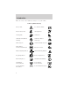
Introduction These are some of the symbols you may see on your vehicle.
Introduction Vehicle Symbol Glossary Child Safety Door Lock/Unlock Interior Luggage Compartment Release Symbol Panic Alarm Engine Oil Engine Coolant Engine Coolant Temperature Do Not Open When Hot Battery Avoid Smoking, Flames, or Sparks Battery Acid Explosive Gas Fan Warning Power Steering Fluid Maintain Correct Fluid Level Emission System Engine Air Filter Passenger Compartment Air Filter Jack MAX MIN 5
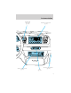
Instrumentation Instrument panel dimmer switch (pg. 24) Instrument cluster (pg. 8) Driver air bag (pg. 101) Headlamp control (pg. 24) AIR SUSP OD OFF CHECK ENGINE 50 40 80 60 70 100 80 120 140 BRAKE 90 60 H L < FUEL FILL DOOR 160 40 20 FUEL 10 0FF AUTO LAMP 100 30 F VOLTS PANEL DIM E 180 20 200 MPH km/h 110 120 P RND21 PUSH INTERIOR HI LO F ON R.DEF. OFF Rear window defroster control (pg. 25) Turn signal and wiper/washer control (pg.
Instrumentation Gearshift with O/D control (pg. 125) Electronic sound system (pg. 35) VOL - PUSH ON H AM OIL CLK ST FM1 BASS TREB BAL FADE TAPE AMS FM L SEEK L SCAN SIDE REW EJ TUNE 1 2 3 4 RSM 5 H 1-2 FF 6 M SET ACC COAST OFF F MAX A/C Climate control systems (pg. 26) NORM A/C HI AUTO OUTSIDE TEMP AUTOMATIC VENT FLOOR FLR • DEF DEF LO Traction control switch* (pg. 120) Clock (pg.
Instrumentation WARNING LIGHTS AND CHIMES Standard instrument cluster AIR SUSP TRAC CNTL LOW FUEL OD OFF CHECK ENGINE 60 H 30 F VOLTS 60 70 50 40 80 20 BRAKE 0000000 100 160 20 E 0 0 0 MPH AIR BAG 90 140 180 10 < FUEL FILL DOOR 120 40 FUEL L 100 80 0 200 km/h 110 120 HTEMP H OIL C L Optional instrument cluster CHECK ENGINE H F S km SPEED CONTROL km/h MPH AIR BAG N O R M 1/2 C E CHECK AIR SUSPENSION OVERDRIVE OFF DOOR AJAR LOW WASHER FLUID km MILES /GAL T
Instrumentation Check engine Your vehicle is equipped with a computer that monitors the engine’s CHECK emission control system. This ENGINE system is commonly known as the On Board Diagnostics System (OBD II). This OBD II system protects the environment by ensuring that your vehicle continues to meet government emission standards. The OBD II system also assists the service technician in properly servicing your vehicle.
Instrumentation Light is blinking: Engine misfire is occurring which could damage your catalytic converter. You should drive in a moderate fashion (avoid heavy acceleration and deceleration) and have your vehicle serviced at the first available opportunity. Under engine misfire conditions, excessive exhaust temperatures could damage the catalytic converter, the fuel system, interior floor coverings or other vehicle components, possibly causing a fire.
Instrumentation Brake system warning • Standard instrument cluster ! BRAKE • Optional instrument cluster BRAKE Momentarily illuminates when the ignition is turned to the ON ! P position. Also illuminates if the parking brake is engaged. If brake warning lamp does not illuminate at these times, seek service immediately. Illumination after releasing the parking brake indicates low brake fluid level and the brake system should be inspected immediately.
Instrumentation Charging system Illuminates when the ignition is turned to the ON position and the engine is off. The light also illuminates when the battery is not charging properly, requiring electrical system service. Engine oil pressure (if equipped) Illuminates when the oil pressure falls below the normal range. Stop the vehicle as soon as safely possible and switch off the engine immediately. Check the oil level and add oil if needed. Refer to Engine oil in the Maintenance and care chapter.
Instrumentation O/D off • Standard instrument cluster O/D OFF • Optional instrument cluster CHECK AIR SUSPENSION DOOR OVERDRIVE OFF AJAR Illuminates when the Transmission Control Switch (TCS), refer to LOW km WASHER MILES Overdrive control in the Controls FLUID /GAL and Features chapter, has been pushed turning the transmission TRUNK AJAR LTR/100 km overdrive function OFF.
Instrumentation Door ajar Illuminates when one of the doors is not completely shut and the ignition is turned to ON. With the ignition ON, this light will flash five times and sound a tone for one second, then remain on (if a door is open). CHECK AIR SUSPENSION OVERDRIVE OFF DOOR AJAR LOW WASHER FLUID km MILES /GAL TRUNK AJAR Low washer fluid Momentarily illuminates when the ignition is turned to ON and will stay on when the windshield washer fluid is low.
Instrumentation Headlamps on warning chime Sounds when the headlamps or parking lamps are on, the ignition is off (and the key is not in the ignition) and the driver’s door is opened.
Instrumentation • Standard instrument cluster F FUEL E • Optional instrument cluster A minimum of four gallons must be added or removed from the fuel tank in order for the gauge to instantaneously update. If less than four gallons is added, the gauge will take between five to ten minutes to update. F 1/2 E Speedometer Indicates the current vehicle speed.
Instrumentation • Optional instrument cluster S km km/h MPH Odometer Registers the total kilometers (miles) of the vehicle. • Standard instrument cluster 60 70 50 40 100 80 80 120 140 90 60 30 0000000 40 20 10 • Optional instrument cluster S 100 160 180 20 0 0 0 MPH 0 km/h 200 110 120 km km/h MPH Refer to Electronic Message Center for information on how to switch the display from metric to English measurements.
Instrumentation Trip odometer Registers the kilometers (miles) of individual journeys. To reset, depress the control. 60 70 50 80 120 100 40 140 80 30 20 60 0 00000 160 100 180 40 km/h 10 90 20 MPH 0 0 0 0 110 120 Refer to Electronic Message Center for Trip A and Trip B features on the optional instrument cluster. Engine coolant temperature gauge Indicates the temperature of the engine coolant.
Instrumentation • Optional instrument cluster H N O R M C This gauge indicates the temperature of the engine coolant, not the coolant level. If the coolant is not at its proper level the gauge indication will not be accurate. If the gauge enters the red section, the engine coolant and Check Engine/Service Engine Soon indicators illuminate, refer to What you should know about fail-safe cooling in the Maintenance and care chapter.
Instrumentation Add oil if needed (refer to Engine oil in the Maintenance and care chapter). If the oil level is correct, have your vehicle checked at your dealership or by a qualified technician. ELECTRONIC MESSAGE CENTER The electronic message center only CHECK AIR SUSPENSION DOOR OVERDRIVE OFF AJAR works when the ignition is in the ON position.
Instrumentation E/M Press this control to switch the electronic instrument cluster display and the message center display from metric to English units. Select Each press of the SELECT control will select a different function. Press the right side of the control to advance the function to the right, and press the left side of the control to advance the function to the left. To reset any function: 1. Push either the right or left side of the SELECT control to choose the desired function. 2.
Instrumentation Remember to turn the ignition OFF when refueling your vehicle. Otherwise, the display will not show the addition of fuel for a few miles. At least four gallons of fuel must be added for the fuel gauge to immediately show the new fuel level.
Instrumentation Press the RESET control while AVG ECON is displayed to reset the function. The average displayed is the average since the last reset. TRIP A and TRIP B These two functions allow you to see how far you have traveled since you last reset. Trip A and Trip B are completely independent and must be reset individually. To reset either trip feature to zero, press the RESET control while the appropriate trip distance feature (TRIP A or TRIP B) is displayed.
Controls and features PANEL DIMMER CONTROL Use to adjust the brightness of the instrument panel during headlight and parklamp operation. • Push up to brighten. • Push down to dim. HEADLAMP CONTROL Rotate the headlamp control to the first position to turn on the parking lamps. Rotate to the second position to also turn on the headlamps. PANEL DIM OFF P To turn on the interior lamps, push the headlamp control in and release. To turn the interior lamps off, push the headlamp control again.
Controls and features High beams Push forward to activate. Pull toward you to deactivate. HI LO F S OFF Flash to pass Pull toward you to activate and release to deactivate. HI LO F S OFF AUTOLAMP CONTROL (IF EQUIPPED) The autolamp system provides light OFF P sensitive automatic on-off control of the exterior lights normally controlled by the headlamp control. The autolamp system also keeps the AUTO lights on for a preselected period of LAMP time after the ignition switch is turned to OFF.
Controls and features Press the rear defroster control to clear the rear window of thin ice and fog. • A small LED will illuminate when the rear defroster is activated. The ignition must be in the ON position to operate the rear window defroster. The defroster turns off automatically after 10 minutes or when the ignition is turned to the OFF position. To manually turn off the defroster before 10 minutes have passed, push the control again.
Controls and features Since the air conditioner removes considerable moisture from the air during operation, it is normal if clear water drips on the ground under the air conditioner drain while the system is working and even after you have stopped the vehicle. • MAX A/C-Uses recirculated air to cool the vehicle. MAX A/C is noisier than NORM A/C but more economical and will cool the inside of the vehicle faster. Airflow will be from the instrument panel registers.
Controls and features • To prevent humidity buildup inside the vehicle, do not drive with the climate control system in the OFF or MAX A/C position. • Do not put objects under the front seat that will interfere with the airflow to the back seats. • Remove any snow, ice or leaves from the air intake area (at the bottom of the windshield).
Controls and features Turning the EATC on Press AUTOMATIC, any of the override controls or the fan speed control. The EATC will only operate when the vehicle is running. HI OFF F AUTO OUTSIDE TEMP MAX A/C NORM A/C AUTOMATIC VENT Turning the EATC off Press OFF. The Outside Temperature function will continue to operate until the ignition is turned off. FLOOR FLR • DEF DEF LO HI OFF AUTOMATIC FLR • DEF DEF LO Automatic operation Press AUTOMATIC and select the desired temperature.
Controls and features To control the temperature, select any temperature between 18°C (65°F) and 29°C (85°F) by pressing the blue (cooler) or red (warmer) buttons. OUTSIDE TEMP MAX A/C VENT NORM A/C For continuous maximum cooling, push the blue button until 16°C (60°F) is shown in the display window. The EATC will continue maximum cooling (disregarding the displayed temperature) until a warmer temperature is selected by pressing the red button.
Controls and features Fan speed ( ) When AUTOMATIC is pressed, fan speed is adjusted automatically for existing conditions. You can override fan speed at any time. To control fan speed manually, use the thumbwheel to cancel automatic fan speed operation. Rotate the thumbwheel up for higher fan speed or down for lower fan speed. HI OFF AUTOMATIC FLR • DEF DEF LO to The display will show indicate manual fan operation. ˚F AUTO To return to automatic fan operation, press AUTOMATIC.
Controls and features • • • • • • 32 economical and will cool the inside of the vehicle faster. Airflow is from the instrument panel registers. This mode can also be used to prevent undesirable odors from entering the vehicle. NORM A/C-Uses outside air to cool the vehicle. The temperature display will remain the same and air will be cooled based on the selected temperature. It is quieter than MAX A/C but not as economical. Fan speed will remain automatic.
Controls and features Displaying outside temperature Press OUTSIDE TEMP to display the outside air temperature. It will be displayed until OUTSIDE TEMP is pressed again. OUTSIDE TEMP MAX A/C NORM A/C VENT If the selected temperature is changed while the outside temperature is displayed, the new temperature will be displayed for four seconds after it is changed, then the outside temperature will return to the window.
Controls and features • Remove any snow, ice or leaves from the air intake area (at the bottom of the windshield). • If your vehicle has been parked with the windows closed during hot weather, the air conditioner will do a much faster job of cooling if you drive for two or three minutes with the windows open. This will force most of the hot, stale air out of the vehicle. Then operate the air conditioner as you would normally. • Do not place objects over the defroster outlets.
Controls and features USING YOUR AUDIO SYSTEM AM/FM stereo cassette VOL - PUSH ON AM CLK ST FM1 BASS TREB BAL FADE FM SEEK SCAN SIDE REW EJ TUNE 1 2 3 Volume/power control Press the control to turn the audio system on or off. Turn the control to raise or lower volume.
Controls and features AM/FM select The AM/FM select control works in radio and tape modes. AM FM AM/FM select in radio mode This control allows you to select AM or FM frequency bands. Press the AM control to select from AM selections, and press the FM control to select from FM1 or FM2 memory preset stations. AM/FM select in tape mode Press this control to stop tape play and begin radio play. Tune adjust The tune control works in radio mode.
Controls and features Scan function The scan function works in radio mode. SCAN Scan function in radio mode Press the SCAN control to hear a brief sampling of all listenable stations on the frequency band. Press the SCAN control again to stop the scan mode. Radio station memory preset The radio is equipped with six station memory preset controls. These controls can be used to select up to six preset AM stations and twelve FM stations (six in FM1 and six in FM2). Setting memory preset stations 1.
Controls and features Treble adjust The treble adjust control allows you to increase or decrease the audio system’s treble output. TREB Speaker balance adjust Speaker sound distribution can be adjusted between the right and left speakers. BAL Speaker fade adjust Speaker sound can be adjusted between the front and rear speakers. FADE Tape select • To enter tape mode while in radio mode, press the TAPE AMS control.
Controls and features Automatic Music Search The Automatic Music Search feature allows you to quickly locate the beginning of the tape selection CLK being played or to skip to the next selection. TAPE To activate the feature, momentarily AMS depress the TAPE AMS button. Then, press either REW (for the beginning of the current selection) or FF (to advance to the next selection). The tape deck stops and returns to play mode when the AMS circuit senses a blank section on the tape.
Controls and features DolbyT noise reduction Dolbyt noise reduction operates only in tape mode. Dolbyt noise 4 reduction reduces the amount of hiss and static during tape playback. Press the control to activate (and deactivate) Dolbyt noise reduction. Dolbyt noise reduction is manufactured under license from Dolbyt Laboratories Licensing Corporation. “Dolbyt” and the double-D symbol are trademarks of Dolby Laboratories Licensing Corporation.
Controls and features Volume/power control Press the control to turn the audio system on or off. Turn the control to raise or lower volume. VOL - PUSH ON VOL - PUSH ON If the volume is set above a certain level and the ignition is turned off, the volume will come back on at a “nominal” listening level when the ignition switch is turned back on. AM/FM select The AM/FM select control works in radio and CD modes.
Controls and features Tune adjust The tune control works in radio mode. Tune adjust in radio mode • Press to move to the next SEEK frequency down the band TUNE (whether or not a listenable DISCS station is located there). Hold the control to move through the frequencies quickly. to move to the next frequency up the band (whether or not • Press a listenable station is located there). Hold for quick movement. Tune adjust in CD changer mode (if equipped) • Press to move to the previous disc.
Controls and features Scan function in radio mode Press the SCAN control to hear a brief sampling of all listenable stations on the frequency band. Press the SCAN control again to stop the scan mode. Scan function in CD or CD changer mode (if equipped) Press the SCAN control to hear a short sampling of all selections on the current CD. (The CD scans in a forward direction, wrapping back to the first track at the end of the CD.) To stop on a particular selection, press the control again.
Controls and features Treble adjust The treble adjust control allows you to increase or decrease the audio system’s treble output. TREB Speaker balance adjust Speaker sound distribution can be adjusted between the right and left speakers. BAL Speaker fade adjust Speaker sound can be adjusted between the front and rear speakers. FADE CD select • To begin CD play (if CD[s] are loaded), press the CD control. The first track of the disc will begin playing.
Controls and features Rewind The rewind control works in CD mode. To rewind in CD mode, press the CD control (preset 1). Press the control again to deactivate rewind mode. Fast forward The fast forward control works in CD mode. To fast forward in CD changer mode, press the CD control (preset 2). Press the control again to deactivate fast forward mode. Eject function Press the control to stop and eject a CD.
Controls and features Premium AM/FM Stereo/Cassette (CD Changer Compatible) BASS BAL SEL TREB VOL PUSH ON CD EJ TAPE AM FM TUNE SEEK MUTE REW FF SIDE 1.2 1 2 3 RDS SCAN 4 FADE AUTO COMP SHUFF 5 6 Your audio system is equipped with selective lighting, a unique lighting strategy. This lighting feature is operable when the headlamps are illuminated. During the operation of any selected mode, lighting for the individual function controls will either illuminate or turn off.
Controls and features Turn the control to raise or lower volume. VOL PUSH ON If the volume is set above a certain level and the ignition is turned off, the volume will come back on at a “nominal” listening level when the ignition switch is turned back on. AM/FM select The AM/FM select control works in radio, tape and CD modes (if equipped). AM FM AM/FM select in radio mode This control allows you to select AM or FM frequency bands.
Controls and features disc unless the CD changer is in shuffle mode.) Refer to Shuffle feature for more information. Hold the control to continue reversing through the discs. • Press to select the next disc in the CD changer. Hold the control to fast-forward through the remaining discs. Seek function The seek function control works in radio, tape or CD mode (if equipped). Seek function in radio mode • Press to find the next SEEK listenable station down the frequency band.
Controls and features Scan function in radio mode Press the SCAN control to hear a brief sampling of all listenable stations on the frequency band. Press the SCAN control again to stop the scan mode. Scan function in tape mode Press the SCAN control to hear a short sampling of all selections on the tape. (The tape scans in a forward direction. At the end of the tape’s first side, direction automatically reverses to the opposite side of the tape.) To stop on a particular selection, press the control again.
Controls and features Starting autoset memory preset 1. Select a frequency using the AM/FM select controls. 2. Press the AUTO control. 3. When the first six strong stations AUTO are filled, the station stored in memory preset control 1 will start playing. If there are less than six strong stations available on the frequency band, the remaining memory preset controls will all store the last strong station available.
Controls and features Speaker fade adjust Speaker sound can be adjusted between the front and rear speakers. Press the FADE control. Use the SEL control to adjust the sound between the front and rear speakers. BAL SEL FADE Tape/CD select • To begin tape play (with a tape loaded into the audio system) CD TAPE while in the radio or CD mode, press the TAPE control. Press the button during rewind or fast forward to stop the rewind or fast forward function.
Controls and features • In CD mode, pressing the control for less than three seconds results in slow forward action. Pressing the control for more than three seconds results in fast forward action. Tape direction select Press SIDE 1–2 to play the alternate side of a tape. SIDE 1-2 3 Eject function Press the control to stop and eject a tape. EJ DolbyT noise reduction Dolbyt noise reduction operates only in tape mode. Dolbyt noise reduction reduces the amount of 4 hiss and static during tape playback.
Controls and features shuffle feature continues to the next disc after all tracks are played. Press the SHUFFLE control to start this feature. Random order play will continue until the SHUFFLE control is pressed again. Mute mode Press the control to mute the playing media. Press the control again to return to the playing media. MUTE Radio data system (RDS) feature This feature allows your audio system to receive station RDS identification or program type from RDS-equipped FM radio stations.
Controls and features Program type • Press the RDS control until the FIND program type is displayed. • Use the SEL control to select the program type. With the feature on, use the SEEK or SCAN control to find the desired program type from the following selections: • Classic • Country • Info • Jazz • Oldies • R&B • Religious • Rock • Soft • Top 40 Show • With RDS activated, press the RDS control until SHOW is displayed.
Controls and features Setting the clock Your vehicle is equipped with a separate instrument panel mounted clock. Please refer to Clock in this chapter for instructions on setting the clock. CD changer (if equipped) The CD changer is located in one of the following locations: • in the trunk • in the center console • under the driver’s seat 1. Slide the door to access the CD changer magazine. 2. Press to eject the magazine.
Controls and features 3. Turn the magazine (A) over. 4. Using the disc holder release knob (C), pull the disc holder (B) out of the magazine. A B C A If you pull too hard on the disc holder, the disc holder may come completely out of the magazine. If this happens, reinsert the disc holder back into the magazine while pressing on the lever (A). 5. Line up the CD with the groove of the disc holder. Ensure that the label on the CD faces downwards. 6.
Controls and features Ensure that the disc holder is evenly inserted and at the same level as the magazine (A). The unit will not operate if the disc holder is not inserted at the same level (B). A B Radio power must be turned on to play the CDs in the changer. The magazine may be stored in the glove box when not being used. The CD magazine may be inserted or ejected with the radio power off. ONLY use the magazine supplied with the CD changer, other types will damage the unit.
Controls and features Cleaning compact discs Inspect all discs for contamination before playing. If necessary, clean discs only with an approved CD cleaner and wipe from the center out to the edge. Do not use circular motion. CD and CD changer care • Handle discs by their edges only. Never touch the playing surface. • Do not expose discs to direct sunlight or heat sources for extended periods of time. • Do not insert more than one disc into each slot of the CD changer magazine.
Controls and features Radio reception factors Three factors can affect radio reception: • Distance/strength. The further an FM signal travels, the weaker it is. The listenable range of the average FM station is approximately 40 km (24 miles). This range can be affected by “signal modulation.” Signal modulation is a process radio stations use to increase their strength/volume relative to other stations. • Terrain.
Controls and features Cornering lamps When the turn signal is used and the headlamps are on, the cornering lamps will light either the right or left side depending on the direction of the turn. WINDSHIELD WIPER/WASHER CONTROLS Rotate the windshield wiper control to the desired interval, low or high speed position. The bars of varying length are for intermittent wipers. When in this position rotate the control upward for fast intervals and downward for slow intervals.
Controls and features TILT STEERING Pull the tilt steering control toward you to move the steering wheel up or down. Hold the control while adjusting the wheel to the desired position, then release the control. Never adjust the steering wheel when the vehicle is moving. OVERDRIVE CONTROL Activating overdrive (Overdrive) is the normal drive position for the best fuel economy. The overdrive function allows automatic upshifts and downshifts through all available gears.
Controls and features The TCIL will no longer be illuminated. When you shut off and re-start your vehicle, the transmission will automatically return to normal (Overdrive) mode. For additional information about the gearshift lever and the transmission control switch operation refer to the Automatic Transmission Operation section of the Driving chapter. SPEED CONTROL (IF EQUIPPED) To turn speed control on • Press ON.
Controls and features Once speed control is switched off, the previously programmed set speed will be erased. To set a speed • Press SET/SET ACC/SET ACCEL. For speed control to operate, the speed control must be ON and the vehicle speed must be greater than 48 km/h (30 mph). RESUME SET ACCEL COAST If you drive up or down a steep hill, your vehicle speed may vary momentarily slower or faster than the set speed. This is normal.
Controls and features • Accelerate with your accelerator pedal. When the desired vehicle speed is reached, press and release SET/SET ACC/SET ACCEL. You can accelerate with the accelerator pedal at any time during speed control usage. Releasing the accelerator pedal will return your vehicle to the previously programmed set speed. To set a lower set speed • Press and hold CST/COAST. Release the control when the desired speed is reached or • Press and release CST/COAST.
Controls and features Pressing OFF will erase the previously programmed set speed. ON OFF To return to a previously set speed • Press RES/RSM/RESUME. For RES/RSM/RESUME to operate, the vehicle speed must be faster than 48 km/h (30 mph). RESUME SET ACCEL COAST Indicator light (if equipped) This light comes on when either the SET ACC/SET ACCEL or RES/RSM/ RESUME controls are pressed.
Controls and features Do not use the HomeLinkt Universal Transceiver with any garage door opener that lacks safety stop and reverse features as required by U.S. federal safety standards (this includes any garage door opener model manufactured before April 1, 1982). A garage door which cannot detect an object, signaling the door to stop and reverse, does not meet current U.S. federal safety standards. For more information on this matter, call toll-free: 1–800–355–3515 or on the Internet at HomeLink.jci.com.
Controls and features Canadian Programming During programming, your hand-held transmitter may automatically stop transmitting after two seconds which may not be long enough to program the HomeLinkt Universal Transceiver. To program your hand-held transmitters: • continue to hold the button on the HomeLinkt Universal Transceiver. • press and re-press the hand-held transmitter button every two seconds until the red light changes from a slow to a fast flash.
Controls and features After completing the “Programming” functions, follow these steps to train a garage door opener with the rolling code feature: 1. Locate the training button on the garage door motor head unit. Refer to the garage door opener manual or call 1–800–355–3515 or on the Internet at HomeLink.jci.com. if there is difficulty locating the training button. 2. Press the training button on the garage door motor head unit (which will activate the “training” light”). 3.
Controls and features 2. When the indicator light begins to flash slowly (after 20 seconds), position the hand-held transmitter 5–14 cm (2 to 5 inches) away from the HomeLinkt surface. 3. Press and hold the hand-held transmitter button. 4. The HomeLinkt indicator light will flash, first slowly and then rapidly. When the indicator light begins to flash rapidly, release both buttons.
Controls and features seconds, then display all segments until the magnetized item is removed. If a “C” is displayed, refer to Compass calibration adjustment. Most geographic areas (zones) have a magnetic north compass point that varies slightly from the northerly direction on maps. This variation is four degrees between adjacent zones and will become noticeable as the vehicle crosses multiple zones. A correct zone setting will eliminate this error. Refer to Compass zone adjustment.
Controls and features 5. The display will show all segments, then return to normal compass mode within ten seconds. Compass calibration adjustment Perform this adjustment in an open area free from steel structures and high voltage lines. 1. Start the vehicle. 2. Press and hold the COMP side of the control for approximately six NW seconds until “C” appears in the mirror display. 3. Drive the vehicle slowly (less than 5 km/h [3 mph]) in circles or on your everyday routine until the display reads a direction.
Controls and features POWER WINDOWS Press and hold the rocker switches to open and close windows. • Press the top portion of the rocker switch to close. AUTO • Press the bottom portion of the rocker switch to open. AUTO Express down • Press AUTO and release quickly. The window will open fully. Depress again to stop window operation.
Controls and features Window lock The window lock feature allows only the driver to operate the power windows. To lock out all the window controls WINDOW LOCK except for the driver’s press the left side of the control. Press the right side to restore the window controls. POWER DOOR LOCKS Press U to unlock all doors and L to lock all doors.
Controls and features 2. Move the control in the direction you wish to tilt the mirror. L R 3. Return to the center position to lock mirrors in place. CHILDPROOF DOOR LOCKS When these locks are set, the rear doors cannot be opened from the inside. The rear doors can be opened from the outside when the doors are unlocked. The childproof locks are located on rear edge of each rear door and must be set separately for each door. Setting the lock for one door will not automatically set the lock for both doors.
Controls and features REMOTE ENTRY SYSTEM (IF EQUIPPED) The remote entry system allows you to lock or unlock all vehicle doors without a key. The remote entry features only operate with the ignition in the OFF position. If there is any potential remote keyless entry problem with your vehicle, ensure ALL key fobs (remote entry transmitters) are brought to the dealership, to aid in troubleshooting. Unlocking the doors Press this control to unlock the driver’s door. The interior lamps will illuminate.
Controls and features You must complete steps 1-7 within 30 seconds or the procedure will have to be repeated. If the procedure needs to be repeated, you must wait 30 seconds. 1. Turn the ignition key to ON. 2. Press the power door unlock control on the door panel three times. 3. Turn the ignition key from ON to OFF. 4. Press the power door unlock control three times. 5. Turn the ignition back to ON. The door locks will cycle lock/unlock. 6. Press the unlock control twice. 7.
Controls and features Automatic door locks can be turned on/off with the keyless entry keypad through the following procedure: You must complete steps 1-5 within 30 seconds or the procedure will have to be repeated. If the procedure needs to be repeated, you must wait 30 seconds. 1. Enter the keyless entry keypad factory code. 2. Within 5 seconds, press and hold control 7/8. 3. Within 5 seconds (while holding down control 7/8), press and release control 3/4. 4. Release control 7/8.
Controls and features Opening the trunk Press the control once to open the trunk. Ensure that the trunk is closed and latched before driving your vehicle. Failure to latch the trunk may cause objects to fall out of the trunk or block the rear view. Sounding a panic alarm Press this control to activate the alarm. To deactivate the alarm, press the control again or turn the ignition to ACC or ON. This device complies with part 15 of the FCC rules and with RS-210 of Industry Canada.
Controls and features Illuminated entry The interior lamps illuminate when the remote entry system is used to unlock the door(s) or sound the personal alarm. The system automatically turns off after 25 seconds after the UNLOCK button on the remote transmitter is pressed or when the ignition is turned to the START or ACC position. The inside lights will not turn off if: • they have been turned on with the dimmer control or • any door is open.
Controls and features Replacing lost transmitters Take all your vehicle’s transmitters to your dealer if service is required. If you purchase additional transmitters (up to four may be programmed into memory), perform the following procedure: To reprogram the transmitters yourself, place the key in the ignition and turn from OFF to ON four times in rapid succession within 3 seconds. After doors lock/unlock, press any control on all transmitters (up to four). When completed, turn the ignition to OFF.
Controls and features and devices cannot damage the PATS ignition key, but can cause a momentary concern if they are too close to the key during engine start. If a problem occurs, turn ignition OFF and restart the engine with all other objects on the key ring held away from the ignition key. Check to make sure the encoded ignition key is an approved Ford encoded ignition key. Spare coded keys can be purchased from your dealership and programmed to your anti-theft system.
Controls and features You will need to have two previously programmed coded keys and the new unprogrammed SecuriLocky key readily accessible for timely implementation of each step in the procedure. Please read and understand the entire procedure before you begin. 1. Insert the first previously programmed coded key into the ignition and turn the ignition from OFF to ON (maintain ignition in ON for at least one second). 2. Turn ignition to OFF and remove the first coded key from the ignition. 3.
Controls and features See also Remote entry system in this chapter for more information. Your vehicle has a factory-set 5–digit code that operates the keyless entry system. You can also program your own 5–digit personal entry code. The factory-set code is located: • on the owner’s wallet card in the glove compartment • taped to the computer module When pressing the controls on the keyless entry keypad, press the middle of the controls to ensure a good activation. Programming your own entry code 1.
Controls and features Erasing personal code To erase all of the personal entry codes programmed to a vehicle: 1. Enter the factory-set code. 1 2 3 4 5 6 7 8 9 0 2. Press 1/2 within 5 seconds of step 1. 3. Press and hold 1/2 for two seconds. All of the vehicle doors will lock and then unlock to confirm erasure.
Controls and features Locking doors with the keyless entry system It is not necessary to enter the factory-set code prior to locking all doors. To lock the doors: Press 7/8 and 9/0 at the same time. 1 2 3 4 5 6 7 8 9 0 INTERIOR LUGGAGE COMPARTMENT RELEASE (IF EQUIPPED) Your vehicle is equipped with a mechanical interior luggage compartment release handle that provides a means of escape for children and adults in the event they become locked inside the luggage compartment.
Controls and features Keep vehicle doors and luggage compartment locked and keep keys out of a child’s reach. Unsupervised children could lock themselves in an open trunk and risk injury. Children should be taught not to play in vehicles. On hot days, the temperature in the trunk or vehicle interior can rise very quickly. Exposure of people or animals to these high temperatures for even a short time can cause death or serious heat-related injuries, including brain damage.
Seating and safety restraints SEATING Head restraints Your vehicle’s seats may be equipped with head restraints which are vertically adjustable. The purpose of these head restraints is to help limit head motion in the event of a rear collision. To properly adjust your head restraints, lift the head restraint so that it is located directly behind your head or as close to that position as possible. Refer to the following to raise and lower the head restraints.
Seating and safety restraints Lift handle to move seat forward or backward. Pull lever up to adjust seatback. Using the manual recline function (if equipped) Never adjust the driver’s seat or seatback when the vehicle is moving. Do not pile cargo higher than the seatbacks to avoid injuring people in a collision or sudden stop. Always drive and ride with your seatback upright and the lap belt snug and low across the hips.
Seating and safety restraints To adjust the front seatback using the manual recliner: • Lift and hold the handle located on the side of the seat. • Lean against the seatback to adjust it to your desired position. You can recline the seat back or bring it forward. • Release the handle when the desired position has been reached. Adjusting the power front seats – door mounted controls The controls for the power seats are located on the inside of each front door.
Seating and safety restraints Press to move the seat forward or backward. Press to move the front portion of the seat cushion up or down. Press to move the rear portion of the seat cushion up or down. Adjusting the power seats – seat mounted controls Never adjust the driver’s seat or seatback when the vehicle is moving. Always drive and ride with your seatback upright and the lap belt snug and low across the hips.
Seating and safety restraints Reclining the seatback can reduce the effectiveness of the seat’s safety belt in the event of a collision. The power seat controls are located on the side of the driver’s seat. Press to raise or lower the seat, or to move the seat forward or backward. Using the power lumbar support (if equipped) The power lumbar control is located on the outboard side of the seat. Press one side of the control to adjust firmness. Press the other side of the control to adjust softness.
Seating and safety restraints All occupants of the vehicle, including the driver, should always properly wear their safety belts, even when an air bag SRS is provided. It is extremely dangerous to ride in a cargo area, inside or outside of a vehicle. In a collision, people riding in these areas are more likely to be seriously injured or killed. Do not allow people to ride in any area of your vehicle that is not equipped with seats and safety belts.
Seating and safety restraints 2. To unfasten, push the release button and remove the tongue from the buckle. The front and rear outboard safety restraints in the vehicle are combination lap and shoulder belts. The front passenger and rear seat outboard safety belts have two types of locking modes described below: Vehicle sensitive mode The vehicle sensitive mode is the normal retractor mode, allowing free shoulder belt length adjustment to your movements and locking in response to vehicle movement.
Seating and safety restraints How to use the automatic locking mode • Buckle the combination lap and shoulder belt. • Grasp the shoulder portion and pull downward until the entire belt is extracted. • Allow the belt to retract. As the belt retracts, you will hear a clicking sound. This indicates the safety belt is now in the automatic locking mode.
Seating and safety restraints Front safety belt height adjustment Your vehicle has safety belt height adjustments for the driver and front passenger. Adjust the height of the shoulder belt so the belt rests across the middle of your shoulder. To lower the shoulder belt height, push the button and slide the height adjuster down. To raise the height of the shoulder belt, slide the height adjuster up. Pull down on the height adjuster to make sure it is locked in place.
Seating and safety restraints Insert the tongue into the correct buckle (the buckle closest to the direction the tongue is coming from). To lengthen the belt, turn the tongue at a right angle to the belt and pull across your lap until it reaches the buckle. To tighten the belt, pull the loose end of the belt through the tongue until it fits snugly across the hips. Shorten and fasten the belt when not in use.
Seating and safety restraints Conditions of operation If... The driver’s safety belt is not buckled before the ignition switch is turned to the ON position... Then... The safety belt warning light illuminates1-2 minutes and the warning chime sounds 4-8 seconds. The safety belt warning light and warning chime turn off. The driver’s safety belt is buckled while the indicator light is illuminated and the warning chime is sounding...
Seating and safety restraints The following are reasons most often given for not wearing safety belts: (All statistics based on U.S. data) Reasons given... Consider... 9Crashes are rare 36 700 crashes occur every day. The more we events9 drive, the more we are exposed to 9rare9 events, even for good drivers. 1 in 4 of us will be seriously injured in a crash during our lifetime. 9I’m not going far9 3 of 4 fatal crashes occur within 25 miles of home.
Seating and safety restraints One time disable Anytime the safety belt is buckled and then unbuckled during an ignition ON cycle, Belt Minder will be disabled for that ignition cycle only. Deactivating/activating the belt minder feature Read steps 1 - 9 thoroughly before proceeding with the deactivation/activation programming procedure.
Seating and safety restraints 6. Within seven seconds of the safety belt warning light turning off, buckle then unbuckle the safety belt. • This will disable Belt Minder if it is currently enabled, or enable Belt Minder if it is currently disabled. 7. Confirmation of disabling Belt Minder is provided by flashing the safety belt warning light four times per second for three seconds. 8.
Seating and safety restraints AIR BAG SUPPLEMENTAL RESTRAINT SYSTEM (SRS) AIR SUSP OD OFF CHECK ENGINE 50 40 80 60 70 100 80 120 140 BRAKE 90 60 H PANEL DIM AUTO LAMP 0FF 10 < FUEL FILL DOOR E VOL - PUSH ON AM FM 180 20 200 MPH km/h P RND21 110 120 FM1 BASS 160 40 20 FUEL L 100 30 F VOLTS HTEMP H TREB CLK ST 10:35 BAL FADE CD TAPE AMS OIL SEEK C L SCAN EJ w f DOLBY B NR TUNE 1 2 3 4 5 REW SIDE FF 1-2 6 PUSH INTERIOR HI LO R.DEF.
Seating and safety restraints Always transport children 12 years old and under in the back seat and always properly use appropriate child restraints. National Highway Traffic Safety Administration (NHTSA) recommends a minimum distance of at least 25 cm (10 inches) between an occupant’s chest and the driver air bag module. Never place your arm over the air bag module as a deploying air bag can result in serious arm fractures or other injuries.
Seating and safety restraints Children and air bags For additional important safety information, read all information on safety restraints in this guide. Children must always be properly restrained. Accident statistics suggest that children are safer when properly restrained in the rear seating positions than in the front seating position. Failure to follow these instructions may increase the risk of injury in a collision. Air bags can kill or injure a child in a child seat.
Seating and safety restraints The air bags inflate and deflate rapidly upon activation. After air bag deployment, it is normal to notice a smoke-like, powdery residue or smell the burnt propellant. This may consist of cornstarch, talcum powder (to lubricate the bag) or sodium compounds (e.g., baking soda) that result from the combustion process that inflates the air bag. Small amounts of sodium hydroxide may be present which may irritate the skin and eyes, but none of the residue is toxic.
Seating and safety restraints • and the electrical wiring which connects the components. The diagnostic module monitors its own internal circuits and the supplemental air bag electrical system warning (including the impact sensors), the system wiring, the air bag system readiness light, the air bag back up power and the air bag ignitors. Determining if the system is operational The SRS uses a readiness light in the instrument cluster or a tone to indicate the condition of the system.
Seating and safety restraints Important child restraint precautions You are required by law to use safety restraints for children in the U.S. and Canada. If small children ride in your vehicle (generally children who are four years old or younger and who weigh 18 kg [40 lbs] or less), you must put them in safety seats made especially for children. Check your local and state or provincial laws for specific requirements regarding the safety of children in your vehicle.
Seating and safety restraints A belt-positioning booster should be used if the shoulder belt rests in front of the child’s face or neck, or if the lap belt does not fit snugly on both thighs, or if the thighs are too short to let the child sit all the way back on the seat cushion when the lower legs hang over the edge of the seat cushion. You may wish to discuss the special needs of your child with your pediatrician.
Seating and safety restraints • Keep the buckle release button pointing up and away from the safety seat, with the tongue between the child seat and the release button, to prevent accidental unbuckling. • Place seat back in upright position. • Put the safety belt in the automatic locking mode. Refer to Automatic locking mode (passenger side front and outboard rear seating positions) (if equipped). Ford recommends the use of a child safety seat having a top tether strap.
Seating and safety restraints 2. Pull down on the shoulder belt and then grasp the shoulder belt and lap belt together. 3. While holding the shoulder and lap belt portions together, route the tongue through the child seat according to the child seat manufacturer’s instructions. Be sure the belt webbing is not twisted. 4. Insert the belt tongue into the proper buckle (the buckle closest to the direction the tongue is coming from) for that seating position until you hear a snap and feel the latch engage.
Seating and safety restraints 5. To put the retractor in the automatic locking mode, grasp the shoulder portion of the belt and pull downward until all of the belt is extracted and a click is heard. 6. Allow the belt to retract. The belt will click as it retracts to indicate it is in the automatic locking mode. 7. Pull the lap belt portion across the child seat toward the buckle and pull up on the shoulder belt while pushing down with your knee on the child seat. 8.
Seating and safety restraints Installing child safety seats in the lap belt seating positions 1. Lengthen the lap belt. To lengthen the belt, hold the tongue so that its bottom is perpendicular to the direction of webbing while sliding the tongue up the webbing. 2. Place the child safety seat in the center seating position. 3. Route the tongue and webbing through the child seat according to the child seat manufacturer’s instructions. 4.
Seating and safety restraints 1. Position the child safety seat on the passenger seat cushion. 2. Route the child safety seat tether strap over the back of the seat. For vehicles with adjustable head restraints, route the tether strap under the head restraint and between the head restraint posts, otherwise route the tether strap over the top of the seatback. 3. Locate the correct anchor for the selected seating position. 4. Open the tether anchor cover. 5. Clip the tether strap to the anchor as shown.
Starting PREPARING TO START YOUR VEHICLE Engine starting is controlled by the powertrain control system. This system meets all Canadian Interference-Causing Equipment standard requirements regulating the impulse electrical field strength of radio noise. When starting a fuel-injected engine, avoid pressing the accelerator before or during starting. Only use the accelerator when you have difficulty starting the engine. For more information on starting the vehicle, refer to Starting the engine in this chapter.
Starting 2. Make sure the headlamps and vehicle accessories are off. 3. Make sure the parking brake is set. HOOD 4. Make sure the gearshift is in P (Park). 5. Turn the key to 4 (ON) without turning the key to 5 (START). 4 If there is difficulty in turning the 3 key, firmly rotate the steering wheel 5 left and right until the key turns freely.
Starting CHECK ENGINE H S km SPEED CONTROL F km/h MPH AIR BAG N O R M 1/2 C E CHECK AIR SUSPENSION OVERDRIVE OFF DOOR AJAR LOW WASHER FLUID km MILES /GAL TRUNK AJAR LTR/100 km DISTANCE TO EMPTY – + TRIP A AVG FUEL ECONOMY TRIP B AVG SPEED PRN D 21 Make sure the corresponding lights illuminate briefly. If a light fails to illuminate, have the vehicle serviced. light may not illuminate. • If the driver’s safety belt is fastened, the STARTING THE ENGINE 1.
Starting Using the engine block heater (if equipped) An engine block heater warms the engine coolant, which improves starting, warms up the engine faster and allows the heater-defroster system to respond quickly. Use of an engine block heater is strongly recommended if you live in a region where temperatures reach -23°C (-10°F) or below. For best results, plug the heater in at least three hours before starting the vehicle.
Starting Important ventilating information If the engine is idling while the vehicle is stopped in an open area for long periods of time, open the windows at least 2.5 cm (one inch). Adjust the heating or air conditioning (if equipped) to bring in fresh air. Improve vehicle ventilation by keeping all air inlet vents clear of snow, leaves and other debris.
Driving BRAKES Your service brakes are self-adjusting. Refer to the scheduled maintenance guide for scheduled maintenance. Occasional brake noise is normal and often does not indicate a performance concern with the vehicle’s brake system. In normal operation, automotive brake systems may emit occasional or intermittent squeal or groan noises when the brakes are applied.
Driving ABS warning lamp ABS The ABS warning lamp in the instrument cluster momentarily illuminates when the ignition is turned to the ON position. If the light does not illuminate momentarily at start up, remains on or continues to flash, the ABS needs to be serviced. With the ABS light on, the anti-lock brake system is disabled and normal ! braking is still effective unless the BRAKE brake warning light also remains illuminated with parking brake released.
Driving The BRAKE warning lamp in the instrument cluster illuminates and remains illuminated (when the ignition is turned ON) until the parking brake is fully released. BRAKE ! P Always set the parking brake fully and make sure the gearshift is latched in P (Park). Turn off the ignition whenever you leave your vehicle. The parking brake is not recommended to stop a moving vehicle. However, if the normal brakes fail, the parking brake can be used to stop your vehicle in an emergency.
Driving The system operates by detecting and controlling wheel spin. The system borrows many of the electronic and mechanical elements already present in the anti-lock braking system (ABS). Wheel-speed sensors allow excess rear wheel spin to be detected by the Traction Controly portion of the ABS computer. Any excessive wheel spin is controlled by automatically applying and releasing the rear brakes in conjunction with engine torque reductions.
Driving The Traction Controly system will be on every time you turn the ignition key from OFF to ON until you deactivate the system using the traction control switch in the glove compartment. STEERING Your vehicle is equipped with power steering. Power steering uses energy from the engine to help steer the vehicle. To prevent damage to the power steering pump: • Never hold the steering wheel to the extreme right or the extreme left for more than a few seconds when the engine is running.
Driving This system keeps the rear of your vehicle at a constant level by automatically adding air or releasing air from the springs. If you exceed the load limit, the rear air suspension may not operate. The air suspension shut-off switch is AIR SUSPENSION located on the left side of the trunk. SWITCH If this switch is in the OFF position, INTERRUPTEUR DE the rear air suspension will not LA SUSPENSION operate.
Driving If your vehicle gets stuck in mud or snow it may be rocked out by shifting from forward and reverse gears, stopping between shifts, in a steady pattern. Press lightly on the accelerator in each gear. Do not rock the vehicle if the engine is not at normal operating temperature or damage to the transmission may occur. Do not rock the vehicle for more than a few minutes or damage to the transmission and tires may occur or the engine may overheat.
Driving R (Reverse) With the gearshift lever in R (Reverse), the vehicle will move backward. Always come to a complete stop before shifting into and out of R (Reverse). N (Neutral) With the gearshift lever in N (Neutral), the vehicle can be started and is free to roll. Hold the brake pedal down while in this gear. Overdrive The normal driving position for the best fuel economy. Transmission operates in gears one through four.
Driving To return to Overdrive mode, press the transmission control switch. The O/D OFF indicator light will no longer be illuminated. Each time the vehicle is started, the transmission will automatically return to normal Overdrive mode. Every time the vehicle is shut off and restarted, you must press the transmission control switch to cancel overdrive operation if the Overdrive mode is not desired.
Driving VEHICLE LOADING Before loading a vehicle, familiarize yourself with the following terms: • Base Curb Weight: Weight of the vehicle including any standard equipment, fluids, lubricants, etc. It does not include passengers or aftermarket equipment. • Payload: Combined maximum allowable weight of cargo, passengers and optional equipment. The payload equals the gross vehicle weight rating minus base curb weight. • GVW (Gross Vehicle Weight): Base curb weight plus payload weight.
Driving Do not exceed the GVWR or the GAWR specified on the certification label. Do not use replacement tires with lower load carrying capacities than the originals because they may lower the vehicle’s GVWR and GAWR limitations. Replacement tires with a higher limit than the originals do not increase the GVWR and GAWR limitations. The Certification Label, found on the inside pillar of the driver’s door, lists several important vehicle weight rating limitations.
Driving Towing trailers beyond the maximum recommended gross trailer weight could result in engine damage, transmission/axle damage, structural damage, loss of control, and personal injury. Preparing to tow Use the proper equipment for towing a trailer, and make sure it is properly attached to your vehicle. See your dealer or a reliable trailer dealer if you require assistance. Hitches Do not use hitches that clamp onto the vehicle bumper. Use a load carrying hitch.
Driving Driving while you tow When towing a trailer: • Ensure that you turn off your speed control. The speed control may shut off automatically when you are towing on long, steep grades. • Consult your local motor vehicle speed regulations for towing a trailer. • Use a lower gear when towing up or down steep hills. This will eliminate excessive downshifting and upshifting for optimum fuel economy and transmission cooling. • Anticipate stops and brake gradually.
Driving • Do not allow waves to break higher than 15 cm (6 inches) above the bottom edge of the rear bumper. Exceeding these limits may allow water to enter critical vehicle components, adversely affecting driveability, emissions, reliability and causing internal transmission damage. Replace the rear axle lubricant anytime the axle has been submerged in water. Rear axle lubricant quantities are not to be checked or changed unless a leak is suspected or repair required.
Driving DRIVING THROUGH WATER Do not drive quickly through standing water, especially if the depth is unknown. Traction or brake capability may be limited and if the ignition system gets wet, your engine may stall. Water may also enter your engine’s air intake and severely damage your engine. If driving through deep or standing water is unavoidable, proceed very slowly. Never drive through water that is higher than the bottom of the hubs (for trucks) or the bottom of the wheel rims (for cars).
Roadside emergencies GETTING ROADSIDE ASSISTANCE To fully assist you should you have a vehicle concern, Ford offers a complimentary roadside assistance program. This program is separate from the New Vehicle Limited Warranty. The service is available: • 24–hours, seven days a week • for the Basic warranty period (Canada) or New Vehicle Limited Warranty period (U.S.
Roadside emergencies Roadside coverage beyond basic warranty In the United States, you may purchase additional roadside assistance coverage beyond this period through the Ford Auto Club by contacting your Ford or Lincoln Mercury dealer. HAZARD FLASHER Use only in an emergency to warn traffic of vehicle breakdown, approaching danger, etc. The hazard flashers can be operated when the ignition is off. • The hazard lights control is located on top of the steering column.
Roadside emergencies The fuel pump shut-off switch is located on the left side of the trunk behind the trunk liner. Use the following procedure to reset the fuel pump shut-off switch. 1. Turn the ignition to the OFF position. 2. Check the fuel system for leaks. 3. If no fuel leak is apparent, reset the fuel pump shut-off switch by pushing in on the reset button. 4. Turn the ignition to the ON position. Pause for a few seconds and return the key to the OFF position. 5.
Roadside emergencies Always replace a fuse with one that has the specified amperage rating. Using a fuse with a higher amperage rating can cause severe wire damage and could start a fire. Standard fuse amperage rating and color COLOR Fuse Rating Mini Fuses Standard Fuses Maxi Fuses 2A 3A 4A 5A 7.
Roadside emergencies 18 16 17 14 15 12 11 10 13 8 7 6 3 4 2 9 5 1 The fuses are coded as follows.
Roadside emergencies Fuse/Relay Location 9 10 11 12 Fuse Amp Rating 30A 10A 5A 18A CB 13 15A 14 20A CB 15 10A 16 17 18 20A 10A 10A Passenger Compartment Fuse Panel Description Blower Motor, A/C-Heater Mode Switch Air Bag Module Radio Lighting Control Module, Flash-to-Pass, Main Light Switch Warning Lamps, Analog Cluster Gauges and Indicators, Electronic Automatic Transmission, Lighting Control Module Window/Door Lock Control, Driver’s Door Module, One Touch Down Anti-Lock Brakes, Instrument Cluste
17 16 8 7 15 RELAY 4 RELAY 3 14 6 12 4 13 11 3 5 10 2 1 9 RELAY 1 RELAY 2 Roadside emergencies The high-current fuses are coded as follows.
Roadside emergencies Fuse/Relay Location 12 13 14 Fuse Amp Power Distribution Box Description Rating 30A** PCM Power Relay, PCM 50A** High Speed Cooling Fan Relay 40A** Rear Window Defrost Relay, Also see Fuse 17 15 50A** Anti-Lock Brake Module 16 — Not Used 17 30A CB Cooling Fan Relay Relay 1 — Rear Defrost Relay Relay 2 — Horn Relay Relay 3 — Cooling Fan Relay Relay 4 — Air Suspension Pump Relay * Mini Fuses ** Maxi Fuses Relays Relays are located in the power distribution box and should be replaced by q
Roadside emergencies When driving with the temporary spare tire do not: • exceed 80 km/h (50 mph) under any circumstances • load the vehicle beyond maximum vehicle load rating listed on the Safety Compliance Label • tow a trailer • use tire chains • drive through an automatic car wash, because of the vehicle’s reduced ground clearance • try to repair the temporary spare tire or remove it from its wheel • use the wheel for any other type of vehicle Tire change procedure To prevent the vehicle from moving whe
Roadside emergencies 5. Loosen each wheel lug nut one-half turn counterclockwise but do not remove them until the wheel is raised off the ground. Refer to Anti-theft lug nuts for information on removing anti-theft lug nuts. On vehicles equipped with Air Suspension, turn OFF the Air Suspension switch prior to jacking, hoisting or towing your vehicle. AIR SUSPENSION SWITCH INTERRUPTEUR DE LA SUSPENSION PNEUMATIQUE WARNING Refer to Air suspension system in the Driving chapter for more information.
Roadside emergencies To lessen the risk of personal injury, do not put any part of your body under the vehicle while changing a tire. Do not start the engine when your vehicle is on the jack. The jack is only meant for changing the tire. • Never use the rear differential as a jacking point. 8. Remove the lug nuts with the lug wrench. 9. Replace the flat tire with the spare tire, making sure the valve stem is facing outward. Reinstall lug nuts until the wheel is snug against the hub.
Roadside emergencies To remove the anti-theft lug nut: 1. Insert the key over the locking lug nut. Make sure you hold the key square to the lug nut. If you hold the key at an angle, you could damage the key and the lug nut. 2. Place the lug nut wrench over the lug nut key and apply pressure on the key with the wrench. 3. Turn the wrench in a counterclockwise direction to remove the lug nut. To install the anti-theft lug nut: 1. Insert the key over the locking lug nut. 2.
Roadside emergencies Do not attempt to push start your vehicle. Automatic transmissions do not have push-start capability. Preparing your vehicle 1. Use only a 12–volt supply to start your vehicle. 2. Do not disconnect the battery of the disabled vehicle as this could damage the vehicle’s electrical system. 3. Park the booster vehicle close to the hood of the disabled vehicle making sure the two vehicles do not touch.
Roadside emergencies + + – – 2. Connect the other end of the positive (+) cable to the positive (+) terminal of the assisting battery. + + – – 3. Connect the negative (-) cable to the negative (-) terminal of the assisting battery. + + – – 4. Make the final connection of the negative (-) cable to an exposed metal part of the stalled vehicle’s engine, away from the battery and the carburetor/fuel injection system.
Roadside emergencies Do not connect the end of the second cable to the negative (-) terminal of the battery to be jumped. A spark may cause an explosion of the gases that surround the battery. 5. Ensure that the cables are clear of fan blades, belts, moving parts of both engines, or any fuel delivery system parts. Jump starting 1. Start the engine of the booster vehicle and run the engine at moderately increased speed. 2. Start the engine of the disabled vehicle. 3.
Roadside emergencies + + – – 2. Remove the jumper cable on the negative (-) connection of the booster vehicle’s battery. + + – – 3. Remove the jumper cable from the positive (+) terminal of the booster vehicle’s battery. + + – – 4. Remove the jumper cable from the positive (+) terminal of the disabled vehicle’s battery.
Roadside emergencies After the disabled vehicle has been started and the jumper cables removed, allow it to idle for several minutes so the engine computer can relearn its idle conditions. WRECKER TOWING If you need to have your vehicle towed, contact a professional towing service or, if you are a member, your roadside assistance center. It is recommended that your vehicle be towed with a wheel lift or flatbed equipment. Do not tow with a slingbelt.
Maintenance and care SERVICE RECOMMENDATIONS To help you service your vehicle: • We highlight do-it-yourself items in the engine compartment for easy location. • We provide a Scheduled Maintenance Guide which makes tracking routine service easy. If your vehicle requires professional service, your dealership can provide necessary parts and service. Check your “Warranty Guide” to find out which parts and services are covered.
Maintenance and care Working with the engine off 1. Set the parking brake and ensure the gearshift is securely latched in P (Park). 2. Turn off the engine and remove the key. 3. Block the wheels to prevent the vehicle from moving unexpectedly. Working with the engine on 1. Set the parking brake and ensure the gearshift is securely latched in P (Park). 2. Block the wheels to prevent the vehicle from moving unexpectedly.
Maintenance and care IDENTIFYING COMPONENTS IN THE ENGINE COMPARTMENT 4.6L SOHC V8 engine 9 2 1 3 4 8 1. 2. 3. 4. 5. 6. 7. 8. 9.
Maintenance and care ENGINE OIL Checking the engine oil Refer to the Scheduled Maintenance Guide for the appropriate intervals for checking the engine oil. 1. Make sure the vehicle is on level ground. 2. Turn the engine off and wait a few minutes for the oil to drain into the oil pan. 3. Set the parking brake and ensure the gearshift is securely latched in P (Park). 4. Open the hood. Protect yourself from engine heat. 5. Locate and carefully remove the engine oil level indicator (dipstick).
Maintenance and care • If the oil level is within this range, the oil level is acceptable. DO NOT ADD OIL. MIN MAX DO NOT OVERFILL • If the oil level is below this mark, engine oil must be added to raise the level within the normal operating range. MIN MAX DO NOT OVERFILL • If required, add engine oil to the engine. Refer to Adding engine oil in this chapter. • Do not overfill the engine with oil. Oil levels above this MIN mark may cause engine damage.
Maintenance and care engine oil filler cap and use a funnel to pour the engine oil into the opening. 3. Recheck the engine oil level. Make sure the oil level is not above the normal operating range on the engine oil level indicator (dipstick). 4. Install the indicator and ensure it is fully seated. 5. Fully install the engine oil filler cap by turning the filler cap clockwise until three clicks can be heard.
Maintenance and care BRAKE FLUID Checking and adding brake fluid Brake fluid should be checked and refilled as needed. Refer to the Scheduled Maintenance Guide for the service interval schedules. 1. Clean the reservoir cap before removal to prevent dirt or water from entering the reservoir. 2. Visually inspect the fluid level. 3. If necessary, add brake fluid from a clean un-opened container until MAX the level reaches MAX. Do not fill above this line. 4.
Maintenance and care WINDSHIELD WASHER FLUID Checking and adding washer fluid Check the washer fluid whenever you stop for fuel. The reservoir is highlighted with a symbol. If the level is low, add enough fluid to fill the reservoir. In very cold weather, do not fill the reservoir all the way. Only use a washer fluid that meets Ford specifications. Refer to Lubricant specifications in the Capacities and specifications chapter.
Maintenance and care • protection against rust and other forms of corrosion. • an accurate temperature readout from the engine coolant gauge. The engine coolant must be maintained at the correct fluid level and concentration to work properly. If the engine coolant fluid level and concentration is not maintained correctly, damage to the engine and cooling system may result. When the engine is cold, check the level of the engine coolant in the reservoir.
Maintenance and care • DO NOT USE Ford Extended Life Engine Coolant F6AZ-19544-AA (orange in color). • DO NOT USE a DEX-COOLt engine coolant or an equivalent engine coolant that meets Ford specification WSS-M97B44-D. • DO NOT USE alcohol or methanol antifreeze or any engine coolants mixed with alcohol or methanol antifreeze. • DO NOT USE supplemental coolant additives in your vehicle. These additives may harm your engine’s cooling system.
Maintenance and care Have your dealer check the engine cooling system for leaks if you have to add more than 1.0 liter (1.0 quart) of engine coolant per month. To avoid scalding hot steam or coolant from being released from the engine cooling system, never remove the radiator cap while the engine is running or hot. Failure to follow this warning may result in damage to the engine’s cooling system and possible severe personal injury.
Maintenance and care Severe climates If you drive in extremely cold climates (less than –36° C [–34° F]): • it may be necessary to increase the coolant concentration above 50%. • NEVER increase the coolant concentration above 60%. • increased engine coolant concentrations above 60% will decrease the overheat protection characteristics of the engine coolant and may cause engine damage.
Maintenance and care How fail-safe cooling works • Standard cluster HTEMP C • Optional cluster H N O R M C If the engine begins to overheat: • the engine coolant temperature gauge will move to the H (hot) area (if your vehicle is equipped with analog gauges). • the engine coolant temperature gauge will illuminate all eight bars and a tone will sound every five seconds for one minute (if your vehicle is equipped with digital gauges). symbol will illuminate.
Maintenance and care Continued operation will increase the engine temperature: symbol will begin to flash. • the • if your vehicle is equipped with digital gauges, the gauge bars will flash and a tone will sound every five seconds for one minute. • the engine will completely shut down, causing steering and braking effort to increase. Once the engine temperature cools, the engine can be re-started. Take your vehicle to a service facility as soon as possible to minimize engine damage.
Maintenance and care CHECKING AND ADDING POWER STEERING FLUID Check the power steering fluid. Refer to the Scheduled Maintenance Guide for the service interval schedules. If adding fluid is necessary, use only MERCONt ATF. 1. Start the engine and let it run until it reaches normal operating temperature (the engine coolant temperature gauge indicator will be near the center of the normal area between H and C). 2. While the engine idles, turn the steering wheel left and right several times. 3.
Maintenance and care Automatic transmission fluid expands when warmed. To obtain an accurate fluid check, drive the vehicle until it is at normal operating temperature (approximately 30 km [20 miles]). If your vehicle has been operated for an extended period at high speeds, in city traffic during hot weather or pulling a trailer, the vehicle should be turned off for about 30 minutes to allow fluid to cool before checking. 1.
Maintenance and care The transmission fluid should be in this range if at normal operating temperature (66°C-77°C [150°F-170°F]). The transmission fluid should be in this range if at ambient temperature (10°C-35°C [50°F-95°F]). High fluid level Fluid levels above the safe range may result in transmission failure. An overfill condition of transmission fluid may cause shift and/or engagement concerns and/or possible damage. High fluid levels can be caused by an overheating condition.
Maintenance and care BATTERY Your vehicle is equipped with a Motorcraft maintenance-free battery which normally does not require additional water during its life of service. However, for severe usage or in high temperature climates, check the battery electrolyte level. Refer to the Scheduled Maintenance Guide for the service interval schedules. Keep the electrolyte level in each cell up to the “level indicator”. Do not overfill the battery cells.
Maintenance and care When lifting a plastic-cased battery, excessive pressure on the end walls could cause acid to flow through the vent caps, resulting in personal injury and/or damage to the vehicle or battery. Lift the battery with a battery carrier or with your hands on opposite corners. Keep batteries out of reach of children. Batteries contain sulfuric acid. Avoid contact with skin, eyes or clothing. Shield your eyes when working near the battery to protect against possible splashing of acid solution.
Maintenance and care R TU LE AD RE N • Always dispose of automotive batteries in a responsible manner. Follow your local authorized standards for disposal. Call your local authorized recycling center to find out more about recycling automotive batteries. RECYCLE AIR FILTER MAINTENANCE Refer to the Scheduled Maintenance Guide for the appropriate intervals for changing the air filter element. When changing the air filter element, use only the Motorcraft air filter element listed.
Maintenance and care 6. Install a new air filter element. Be careful not to crimp the filter element edges between the air filter housing and cover. This could cause filter damage and allow unfiltered air to enter the engine if not properly seated. 7. Replace the air filter housing cover and secure the clamps. 8. Replace the air inlet tube and secure the clamp. Failure to use the correct air filter element may result in severe engine damage.
Maintenance and care To replace the wiper blades: 1. Pull the wiper arm away from the windshield and lock into the service position. 2. Turn the blade at an angle from the wiper arm. Push the lock pin manually to release the blade and pull the wiper blade down toward the windshield to remove it from the arm. 3. Attach the new wiper to the wiper arm and press it into place until a click is heard.
Maintenance and care Treadwear The treadwear grade is a comparative rating based on the wear rate of the tire when tested under controlled conditions on a specified government test course. For example, a tire graded 150 would wear one and one-half (1 1/2) times as well on the government course as a tire graded 100.
Maintenance and care SERVICING YOUR TIRES Checking the tire pressure • Use an accurate tire pressure gauge. • Check the tire pressure when tires are cold, after the vehicle has been parked for at least one hour or has been driven less than 5 km (3 miles). • Adjust tire pressure to recommended specifications found on the Tire Pressure label. Improperly inflated tires can affect vehicle handling and can fail suddenly, possibly resulting in loss of vehicle control.
Maintenance and care • Five tire rotation (for vehicles with steel wheels and full size spare tires) Replacing the tires Replace the tires when the wear band is visible through the tire treads. When replacing full size tires, never mix radial bias-belted, or bias-type tires. Use only the tire sizes that are listed on the Certification Label. Make sure that all tires are the same size, speed rating, and load-carrying capacity. Use only the tire combinations recommended on the label.
Maintenance and care Failure to follow these precautions may adversely affect the handling of the vehicle and make it easier for the driver to lose control and roll over. Tires that are larger or smaller than your vehicle’s original tires may also affect the accuracy of your speedometer. SNOW TIRES AND CHAINS Snow tires must be the same size and grade as the tires you currently have on your vehicle. The tires on your vehicle have all weather treads to provide traction in rain and snow.
Maintenance and care The fuel system may be under pressure. If the fuel filler cap is venting vapor or if you hear a hissing sound, wait until it stops before completely removing the fuel filler cap. Otherwise, fuel may spray out and injure you or others. If you do not use the proper fuel filler cap, excessive pressure or vacuum in the fuel tank may damage the fuel system or cause the fuel system to work improperly in a collision, which may result in possible personal injury.
Maintenance and care • Avoid getting fuel liquid in your eyes. If fuel is splashed in the eyes, remove contact lenses (if worn), flush with water for 15 minutes and seek medical attention. Failure to seek proper medical attention could lead to permanent injury. • Fuels can also be harmful if absorbed through the skin. If fuel is splashed on the skin and/or clothing, promptly remove contaminated clothing and wash skin thoroughly with soap and water.
Maintenance and care When fueling your vehicle: 1. Turn the engine off. 2. Carefully turn the filler cap counterclockwise 1/8 of a turn until it stops. 3. Pull to remove the cap from the fuel filler pipe. 4. To install the cap, align the tabs on the cap with the notches on the filler pipe. 5. Turn the filler cap clockwise 1/8 of a turn until it stops. If the “Service Engine Soon/Check Engine” indicator comes on and stays on when you start the engine, the fuel filler cap may not be properly installed.
Maintenance and care Octane recommendations Your vehicle is designed to use “Regular” unleaded gasoline with an (R+M)/2 octane rating of 87. We do not recommend the use of gasolines (R+M)/2 METHOD labeled as “Regular” that are sold with octane ratings of 86 or lower in high altitude areas. Do not be concerned if your engine sometimes knocks lightly.
Maintenance and care If you have run out of fuel: • You may need to cycle the ignition from OFF to ON several times after refueling, to allow the fuel system to pump the fuel from the tank to the engine. • Your “Check Engine” indicator may come on. For more information on the “Check Engine” indicator, refer to the Instrumentation chapter. Fuel Filter For fuel filter replacement, see your dealer or a qualified service technician.
Maintenance and care For consistent results when filling the fuel tank: • Use the same filling rate setting (low — medium — high) each time the tank is filled. • Allow three automatic click-offs when filling. • Always use fuel with the recommended octane rating. • Use a known quality gasoline, preferably a national brand. • Use the same side of the same pump and have the vehicle facing the same direction each time you fill up. • Have the vehicle loading and distribution the same every time.
Maintenance and care Habits • Smooth, moderate operation can yield up to 10% savings in fuel. • Steady speeds without stopping will usually give the best fuel economy. • Idling for long periods of time (greater than one minute) may waste fuel. • Anticipate stopping; slowing down may eliminate the need to stop. • Sudden or hard accelerations may reduce fuel economy. • Slow down gradually. • Driving at reasonable speeds (traveling at 88 km/h [55 mph] uses 15% less fuel than traveling at 105 km/h [65 mph]).
Maintenance and care • Carrying unnecessary weight may reduce fuel economy (approximately 0.4 km/L [1 mpg] is lost for every 180 kg [400 lb] of weight carried). • Adding certain accessories to your vehicle (for example bug deflectors, rollbars/light bars, running boards, ski/luggage racks) may reduce fuel economy. • Using fuel blended with alcohol may lower fuel economy. • Fuel economy may decrease with lower temperatures during the first 12–16 km (8–10 miles) of driving.
Maintenance and care The scheduled maintenance items listed in the Scheduled Maintenance Guide are essential to the life and performance of your vehicle and to its emissions system. If other than Ford, Motorcraft or Ford-authorized parts are used for maintenance replacements or for service of components affecting emission control, such non-Ford parts should be equivalent to genuine Ford Motor Company parts in performance and durability.
Maintenance and care If the vehicle’s powertrain system or its battery has just been serviced, the on-board diagnostics system is reset to a “not ready for I/M test” condition. To ready the on-board diagnostics system for I/M testing, a minimum of 30 minutes of city and highway driving is necessary as described below: • First, at least 10 minutes of driving on an expressway or highway. • Next, at least 20 minutes driving in stop-and-go, city-type traffic with at least four idle periods.
Maintenance and care 3. Disconnect the electrical connector from the bulb by pulling rearward. 4. Remove the bulb retaining ring by rotating it counterclockwise (when viewed from the rear) to free it from the bulb socket, and slide the ring off the plastic base. Keep the ring to retain the new bulb. 5. Without turning, remove the old bulb from the lamp assembly by gently pulling it straight back out of the lamp assembly.
Maintenance and care 5. Turn the headlamps on and make sure they work properly. If the headlamp was correctly aligned before you changed the bulb, you should not need to align it again. Replacing front parking lamp/turn signal bulbs The park/turn lamp bulbs can be replaced with out removing the headlamp assembly. 1. Make sure headlamp switch is in OFF position, then open the hood. 2. Remove the protective cover by turning the three knobs to the unlock position. 3.
Maintenance and care 1. Open the trunk and carefully pull the carpet away to expose the plastic retainer. 2. Remove plastic retainer to expose the lamp assembly hardware. 3. Remove three nut and washer assemblies and the lamp assembly from the vehicle. 4. Remove the bulb socket by rotating it counterclockwise, then pulling it out of the lamp assembly. 5. Pull the bulb from the socket and push in the new bulb. 6. Install the bulb socket into the lamp assembly by rotating it clockwise. 7.
Maintenance and care Replacing license plate lamp bulbs 1. Remove two screws, grommets and the license plate lamp assembly from the trunk lid. 2. Carefully pull the bulb from the socket and push in the new bulb. 3. Install the lamp assembly on trunk lid with two grommets, ensuring the grommets are pushed all the way in to the trunk lid and secure with two screws. Replacing backup lamp bulbs 1. Open trunk and remove bulb socket from the trunk lid by turning counterclockwise. 2.
Maintenance and care Function Trade Number Headlamp 9007 Park lamp and turn lamp (front) 3457 NAK (amber) Side marker (front) 194 NA (amber) Cornering lamp (front) 3156K Tail, stop, turn (rear) 3157 K Side marker (rear) 194 Backup lamp 3156K License plate lamp 168 High-mount brakelamp 912 Luggage compartment lamp 212-2 Dome lamp 906 Rear reading lamp 211-2 Map lamp 168 Illuminated visor mirror 168 Dual floorwell lamp 906 Glove compartment 168 All replacement bulbs are clear in color except where noted.
Maintenance and care Washing your vehicle Wash your vehicle regularly with cold or lukewarm water. Never use strong detergents or soap. If your vehicle is particularly dirty, use a quality car wash detergent. Always use a clean sponge, washing glove or similar device and plenty of water for best results. To avoid spots, avoid washing when the hood is still warm, immediately after or during exposure to strong sunlight. During winter months, it is especially important to wash the vehicle on a regular basis.
Maintenance and care Repairing paint chips Minor scratches or paint damage from road debris may be repaired with the Ultra Touch Prep and Finishing Kit (#F7AZ-19K507–BA), Lacquer Touch-up Paint (#ALBZ-19500–XXXXA), or Exterior Acrylic Spray Lacquer (#ALAZ-19500–XXXXA) from the Ford Car Care Chemicals line. Please note that the part numbers (shown as XXXX above) will vary with your vehicle’s specific coloring. Observe the application instructions on the products.
Maintenance and care To avoid scratching the lamps, do not use a dry paper towel, chemical solvents or abrasive cleaners. Cleaning the wiper blades, windshield and rear window If the wiper blades do not wipe properly, clean the wiper blade rubber element with undiluted windshield washer solution or a mild detergent. To avoid damaging the blades, do not use fuel, kerosene, paint thinner or other solvents.
Maintenance and care • Cover the highlighted areas to prevent water damage when cleaning the engine. • Never wash or rinse the engine while it is running; water in the running engine may cause internal damage. Cleaning the instrument panel Clean with a damp cloth, then dry with a dry cloth. Avoid cleaner or polish that increases the gloss of the upper portion of the instrument panel. The dull finish in this area helps protect the driver from undesirable windshield reflection.
Maintenance and care Cleaning seats equipped with side air bags Remove dust and loose dirt with a whisk broom or a vacuum cleaner. Remove fresh spots immediately. Follow the directions that come with the cleaner. Do not saturate the seat cover with upholstery cleaner. Do not use chemical solvents or strong detergents when cleaning the seat mounted side air bag. Such products could contaminate the side air bag system and affect performance of the side air bag in a collision.
Maintenance and care Cleaning leather seats (if equipped) To clean, simply use a soft cloth dampened with water and a mild soap. Wipe the leather again with a damp cloth to remove soap residue. Dry with a soft cloth. For tougher soiling concerns, Ford recommends using the Deluxe Leather Care Kit F8AZ-19G253–AA, which is available from your Ford Dealer. This mild cleaner and special pad, cleans the leather and maintains its natural beauty. Follow the instructions on the cleaner label.
Capacities and specifications MOTORCRAFT PART NUMBERS Component Air filter element Fuel filter Battery-standard Battery-heavy duty Oil filter PCV valve Spark plugs* 4.6L SOHC V8 engine FA-1668 FG-986B BXT-65–650 BXT-65–750 FL-820-S EV-98 AWSF-32P * Refer to Vehicle Emissions Control Information (VECI) decal for spark plug gap information.
Capacities and specifications MERCONt V. Refer to the Scheduled Maintenance Guide to determine the correct service interval. 3 Indicates only approximate dry-fill capacity. Some applications may vary based on cooler size and if equipped with an in-tank cooler. The amount of transmission fluid and fluid level should be set by the indication on the dipstick’s normal operating range. Police Package refill capacity-12.1L (12.8 quarts). 4 Use Ford Premium Engine Coolant (green in color).
Capacities and specifications Item Engine oil Hinges, latches, striker plates, fuel filler door hinge and seat tracks Lock cylinders Power steering fluid Automatic transmission (4R70W) Rear Axle Lubricant 2 Windshield washer fluid Ford part name Motorcraft SAE 5W-30 Super Premium Motor Oil Multi-Purpose Grease Ford part number XO-5W30-QSP Ford specification WSS-M2C153-G with API Certification Mark DOAZ-19584-AA ESB-M1C93-B or or ESR-M1C159-A F5AZ-19G209-AA Penetrating and Lock Lubricant Motorcraft MERC
Capacities and specifications ENGINE DATA Engine Cubic inches Required fuel Firing order Spark plug gap Ignition system Compression ratio 4.6L V8 engine 281 87 octane 1-3-7-2-6-5-4-8 1.3-1.4 mm (0.052-0.056 inch) Coil on plug 10.0:1 VEHICLE DIMENSIONS Vehicle dimensions (1) Overall length (2) Overall width (3) Overall height (4) Wheelbase (5) Track - Front (5) Track - Rear 200 mm (in) 5 382 (211.9) 1 987 (78.2) 1 443 (56.8) 2 913 (114.4) 1 611 (63.4) 1 659 (65.
Capacities and specifications 3 5 2 4 1 201
Capacities and specifications IDENTIFYING YOUR VEHICLE Certification label The National Highway Traffic Safety Administration Regulations require that a Certification Label be affixed to a vehicle and prescribe where the Certification Label may be located. The Certification Label is located on the front door latch pillar on the driver’s side. MFD. BY FORD MOTOR CO. IN U.S.A.
Customer assistance Ford Extended Service Plan You can get more protection for your new car or light truck by purchasing Ford Extended Service Plan (Ford ESP) coverage. Ford ESP is an optional service contract which is backed by Ford Motor Company or Ford Motor Service Company (in the U.S.) and Ford of Canada (in Canada).
Customer assistance If you have questions or concerns, or are unsatisfied with the service you are receiving, follow these steps: 1. Contact your Sales Representative or Service Advisor at your selling/servicing dealership. 2. If your inquiry or concern remains unresolved, contact the Sales Manager or Service Manager at the dealership. 3. If the inquiry or concern cannot be resolved at the dealership level, please contact the Ford Customer Assistance Center.
Customer assistance If you own a Lincoln vehicle and are away from home when your vehicle needs service, or if you need more help than the dealership could provide, after following the steps described above, contact the Ford Customer Assistance Center to find an authorized dealership to help you. In the United States: Ford Motor Company Customer Assistance Center 16800 Executive Plaza Drive P.O.
Customer assistance dispute handling procedure is not required prior to enforcing state created rights or other rights which are independent of the MagnusonMoss Warranty Act or state replacement or repurchase laws. THE DISPUTE SETTLEMENT BOARD (U.S. ONLY) The Dispute Settlement Board is: • an independent, third-party arbitration program for warranty disputes • available free to owners and lessees of qualifying Ford Motor Company vehicles The Dispute Settlement Board may not be available in all states.
Customer assistance Eligibility may differ according to state law. For example, see the unique brochures for California, West Virginia, Georgia and Wisconsin purchasers/lessees. Board membership The Board consists of: • three consumer representatives • a Ford or Lincoln Mercury dealership representative Consumer candidates for Board membership are recruited and trained by an independent consulting firm.
Customer assistance • the names (if known) of all the people you contacted at the dealership(s) • a description of the action you expect to resolve your concern You will receive a letter of explanation if your application does not qualify for Board review. Oral presentations If you would like to make an oral presentation, indicate YES to question #6 on the application.
Customer assistance You may also contact the North American Customer Assistance Center at 1-800-392-3673 (Ford), TDD for the hearing impaired: 1-800-232-5952 or by writing to the Center at the following address: Ford Motor Company Customer Assistance Center 16800 Executive Plaza Drive P.O.
Customer assistance The use of leaded fuel in your vehicle without proper conversion may damage the effectiveness of your emission control system and may cause engine knocking or serious engine damage. Ford Motor Company/Ford of Canada is not responsible for any damage caused by use of improper fuel. In the United States, using leaded fuel may also result in difficulty importing your vehicle back into the U.S.
Customer assistance Ford Deluxe Leather and Vinyl Cleaner (not available in Canada) Motorcraft Vinyl Cleaner (Canada only) Ford Extra Strength Tar and Road Oil Remover* (not available in Canada) Ford Extra Strength Upholstery Cleaner (Canada only) Ford Extra Strength Upholstery Cleaner (not available in Canada) Ford Metal Surface Cleaner Ford Multi-Purpose Cleaner* Motorcraft Car Wash Concentrate Motorcraft Carlite Glass Cleaner Ford Spot and Stain Remover* Ford Super Premium Tire and Trim Dressing Ford Tri
Customer assistance Comfort and convenience Cargo nets Cargo organizers Engine block heaters Travel equipment Daytime running lights Heavy-duty battery Protection and appearance equipment Air bag anti-theft locks Carpet floor mats Cleaners, waxes and polishes Flat splash guards Front end covers Lubricants and oils Molded splash guards Molded vinyl floor mats Touch-up paint Universal floor mats For maximum vehicle performance, keep the following information in mind when adding accessories or equipment to you
Customer assistance • Mobile communications systems may harm the operation of your vehicle, particularly if they are not properly designed for automotive use or are not properly installed. When operated, such systems may cause the engine to stumble or stall. In addition, such systems may be damaged or their performance may be affected by operating your vehicle.
Reporting safety defects REPORTING SAFETY DEFECTS (U.S. ONLY) If you believe that your vehicle has a defect that could cause a crash, or could cause injury or death, you should immediately inform the National Highway Traffic Safety Administration (NHTSA) in addition to notifying Ford Motor Company. If NHTSA receives similar complaints, it may open an investigation, and if it finds that a safety defect exists in a group of vehicles, it may order a recall and remedy campaign.
Index Air bag supplemental restraint system ........................101 and child safety seats ............103 description ..............................101 disposal ....................................105 driver air bag ..........................103 indicator light ....................10,105 operation .................................103 passenger air bag ...................103 Air cleaner filter ................169,197 Air conditioning ..........................26 automatic temperature control system ....
Index set zone adjustment .................70 Controls power seat ............................89,90 Coolant checking and adding ..............157 coolant temperature light ........10 refill capacities .................160,197 specifications ...................198,200 Cruise control (see Speed control) ....................62 Customer Assistance ................133 Ford accessories for your vehicle ......................210 Ford Extended Service Plan ............................
Index quality ......................................179 running out of fuel .................179 safety information relating to automotive fuels ................175 Fuses ...................................135,136 Garage door opener ....................65 Gas cap (see Fuel cap) ............177 Gas mileage (see Fuel economy) .................180 Gauges .........................................15 battery voltage gauge ...............19 engine coolant temperature gauge ...................
Index anti-lock brakes (ABS) .....11,119 brake ..........................................11 charging system ........................12 check engine ...............................9 high beam .................................11 low coolant ................................10 low fuel ........................................8 oil pressure ...............................12 overdrive off ..............................13 safety belt .................................10 speed control ............................
Index Specification chart, lubricants ............................198,200 Speed control ..............................62 Speedometer ...............................16 Starting your vehicle .........113,115 jump starting ..........................144 Steering speed sensitive .......................122 Steering wheel tilting .........................................61 Tilt steering wheel ......................61 Tires ......................140,171,172,173 changing ...........................
Filling station information Required fuel Fuel tank capacity Engine oil capacity (includes filter change) Tire pressure and size Hood release Coolant capacity 1 Automatic transmission fluid capacity 2 Power steering fluid capacity Unleaded fuel only - 87 octane 71.9L (19.0 gallons) 4.7L (5.0 quarts). Use Motorcraft SAE 5W-30 Super Premium Motor Oil, Ford specification WSS-M2C153-G. Refer to the Tire Pressure Label located on the rear passenger door jamb.