www.carburetor-manual.com Would you like some Free Manuals? http://carburetor-manual.com/free-shop-manual-club-t-13.html Also visit http://freeshopmanual.com for more Free Manuals Also Visit my website for 7 FREE Download Manuals starting with this one. "The ABC's of Carburetion" Click Here Now file:///C|/Documents%20and%20Settings/Tim/Desktop/carburetor-manual-welcome/index.
Table of Contents Introduction Instrument Cluster 4 10 Warning and control lights Gauges 10 15 Entertainment Systems 20 AM/FM stereo cassette (CD changer compatible) AM/FM stereo cassette with CD Rear seat controls CD changer Climate Controls Manual heating and air conditioning Electronic automatic temperature control Lights Headlamps Turn signal control Bulb replacement Driver Controls Windshield wiper/washer control Steering wheel adjustment Power windows Mirrors Speed control Message center 20
Table of Contents Seating and Safety Restraints Seating Safety restraints Air bags Child restraints Driving 115 129 136 141 155 Starting Brakes Transmission operation Vehicle loading Trailer towing Recreational towing 155 158 162 167 169 172 Roadside Emergencies 173 Getting roadside assistance Hazard flasher switch Fuel pump shut-off switch Fuses and relays Changing tires Jump starting Wrecker towing Customer Assistance The dispute settlement board Utilizing the mediation/arbitration Getting assist
Table of Contents Cleaning 203 Maintenance and Specifications 209 Hood Engine compartment Engine oil Battery Fuel information Air filter(s) Part numbers Refill capacities Lubricant specifications Engine data Vehicle dimensions 210 211 212 215 221 234 239 239 240 241 242 Accessories 245 Index 248 All rights reserved.
Introduction The following warning may be required by California law: CALIFORNIA Proposition 65 Warning WARNING: Engine exhaust, some of its constituents, and certain vehicle components contain or emit chemicals known to the State of California to cause cancer and birth defects or other reproductive harm.
Introduction Additional owner information is given in separate publications. This Owner’s Guide describes every option and model variant available and therefore some of the items covered may not apply to your particular vehicle. Furthermore, due to printing cycles it may describe options before they are generally available. Remember to pass on the Owner’s Guide when reselling the vehicle. It is an integral part of the vehicle.
Introduction Protecting the environment We must all play our part in protecting the environment. Correct vehicle usage and the authorized disposal of waste cleaning and lubrication materials are significant steps towards this aim. Information in this respect is highlighted in this guide with the tree symbol. BREAKING-IN YOUR VEHICLE There are no particular guidelines for breaking-in your vehicle. During the first 1 600 km (1 000 miles) of driving, vary speeds frequently.
Introduction Special instructions For your added safety, your vehicle is fitted with sophisticated electronic controls. By operating other electronic equipment (e.g. mobile telephone without exterior aerial) electromagnetic fields can occur which can cause malfunctions of the vehicle electronics. Therefore you should observe the instructions of the equipment manufacturers. Please read the section Air bag in the Seating and safety restraints chapter.
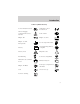
Introduction These are some of the symbols you may see on your vehicle.
Introduction Vehicle Symbol Glossary Power Window Lockout Child Safety Door Lock/Unlock Interior Luggage Compartment Release Symbol Panic Alarm Engine Oil Engine Coolant Engine Coolant Temperature Do Not Open When Hot Battery Avoid Smoking, Flames, or Sparks Battery Acid Explosive Gas Fan Warning Power Steering Fluid Maintain Correct Fluid Level MAX MIN Emission System Engine Air Filter Passenger Compartment Air Filter Jack Check fuel cap Low tire warning 9
Instrument Cluster WARNING LIGHTS AND CHIMES Warning lights and gauges can alert you to a vehicle condition that may become serious enough to cause expensive repairs. A warning light may illuminate when a problem exists with one of your vehicle’s functions. Many lights will illuminate when you start your vehicle to make sure the bulb works. If any light remains on after starting the vehicle, have the respective system inspected immediately.
Instrument Cluster Light turns on solid: Temporary malfunctions may cause the light to illuminate. Examples are: 1. The vehicle has run out of fuel. 2. Poor fuel quality or water in the fuel. 3. The fuel cap may not have been properly installed and securely tightened. These temporary malfunctions can be corrected by filling the fuel tank with high quality fuel of the recommended octane and/or properly installing and securely tightening the fuel cap.
Instrument Cluster To confirm the brake system warning light is functional, it will momentarily illuminate when the ignition is turned to the ON position (alternatively for some vehicles when the ignition is moved from the ON position to START position, the light will momentarily illuminate prior to reaching the START position). It also illuminates if the parking brake is engaged. If the brake system warning light does not illuminate as described, seek service immediately.
Instrument Cluster • Optional electronic instrument cluster AIR BAG Illuminates to confirm that the air bags are operational. If the light fails to illuminate, continues to flash or remains on, have the system serviced immediately. Charging system Illuminates when the battery is not charging properly. Engine oil pressure Illuminates when the oil pressure falls below the normal range. Check the oil level and add oil if needed. Refer to Engine oil in the Maintenance and specifications chapter.
Instrument Cluster The “SET” light comes on when either the COAST/SET or RES/ACCEL controls are pressed. The “SET” light turns off when the cruise cancel control is pressed or the brake is applied. Both the “CRUISE” and “SET” lights turn off when the OFF control is pressed or the ignition is turned to the OFF position. • Optional electronic instrument CRUISE cluster This light comes on when either the COAST/SET or RES/ACCEL controls are pressed.
Instrument Cluster High beams Illuminates when the high beam headlamps are turned on. Safety belt warning chime Sounds to remind you to fasten your safety belts. Headlamps on warning chime Sounds when the headlamps or parking lamps are on, the key is removed from the ignition and the driver’s door is opened. Key-in-ignition warning chime Sounds when the key is left in the ignition and the driver’s door is opened.
Instrument Cluster Optional electronic instrument cluster gauges CRUISE 5 6 7 8 F 2 ˚F ˚C MILES/BAL L/100 km OUTSIDE TEMP INST ECONOMY AVG. ECONOMY TO EMPTY 4 3 H 1 0 X 1000 TRIP 1 TRIP 2 RPM MPH km/h km E FUEL DOOR AIR BAG ! P BRAKE P R N D 2 1 N O R M A L 1/2 C UNLEADED FUEL ONLY SERVICE ENGINE SOON ABS O/D OFF Engine coolant temperature gauge Indicates the temperature of the engine coolant.
Instrument Cluster • Optional electronic instrument cluster H N O R M A L C Fuel gauge Displays approximately how much fuel is in the fuel tank. The fuel gauge may vary slightly when the vehicle is in motion or on a grade. When refueling the vehicle from empty indication, the amount of fuel that can be added will be less than the advertised capacity due to the reserve fuel.
Instrument Cluster Speedometer Indicates the current vehicle speed. • Standard analog instrument cluster 40 30 60 40 20 10 50 60 70 80 100 120 80 140 20 90 160 MPH km/h 0 100 TRIP A • Optional electronic instrument cluster CRUISE 4 3 5 6 7 8 2 MPH km/h km 1 X 1000 TRIP 1 TRIP 2 RPM 0 Odometer Registers the total kilometers (miles) of the vehicle.
Instrument Cluster Trip odometer Registers the kilometers (miles) of individual journeys. • Standard analog instrument cluster To reset, press and hold the control for one second. • Optional electronic instrument 4 cluster CRUISE 3 Refer to Electronic Message Center 2 in the Driver controls chapter for 1 information on how to switch the 0 display from Trip 1 and Trip 2 features on the electronic instrument cluster.
Entertainment Systems AM/FM STEREO/CASSETTE (CD CHANGER COMPATIBLE) VOL - PUSH ON AM FM CLK BASS TREB BAL FADE CD SEEK SCAN TUNE SIDE 1 - 2 EJ REW DISCS CD 1 CD 2 3 Volume/power control Press the control to turn the audio system on or off. Turn the control to raise or lower volume.
Entertainment Systems Bass adjust The bass adjust control allows you to increase or decrease the audio system’s bass output. BASS Treble adjust The treble adjust control allows you to increase or decrease the audio system’s treble output. TREB Speaker balance adjust Speaker sound distribution can be adjusted between the right and left speakers.
Entertainment Systems Speaker fade adjust Speaker sound can be adjusted between the front and rear speakers. FADE Seek function The seek function control works in radio or CD changer mode. Seek function in radio mode to find the next • Press listenable station down the frequency band. to find the next • Press listenable station up the frequency band. SEEK TUNE DISCS Seek function for CD changer (if equipped) • Press to seek to the previous SEEK track of the current disc.
Entertainment Systems Scan function in CD changer mode (if equipped) Press the SCAN control to hear a brief sampling of all selections on the CD. (The CD scans in a forward direction, wrapping back to the first track at the end of the CD.) To stop on a particular selection, press the SCAN control again. AM/FM select The AM/FM select control works in radio, tape and CD changer modes (if equipped). AM FM CD AM/FM select in radio mode This control allows you to select AM or FM frequency bands.
Entertainment Systems 3. Press and hold a memory preset control until the sound returns, indicating the station is held in memory on the control you selected. CD 1 CD 2 3 Setting the clock Press CLK to toggle between listening frequencies and clock mode while in radio mode. To set the hour, press and hold the CLK control and press the SEEK control: • to decrease hours and • to increase hours.
Entertainment Systems Tune adjust The tune control works in radio and CD changer modes (if equipped). Tune adjust in radio mode to move to the next • Press frequency down the band (whether or not a listenable station is located there). Hold the control to move through the frequencies quickly. SEEK TUNE DISCS to move to the next frequency up the band (whether or not • Press a listenable station is located there). Hold for quick movement.
Entertainment Systems Automatic Music Search The Automatic Music Search feature allows you to quickly locate the CLK beginning of the tape selection being played or to skip to the next selection. TAPE AMS To activate the feature, momentarily depress the TAPE AMS button. Then, press either REW (for the beginning of the current selection) or FF (to advance to the next selection). The tape deck stops and returns to play mode when the AMS circuit senses a blank section on the tape.
Entertainment Systems Fast forward The fast forward control works in tape and CD changer modes. To fast forward in tape mode, press SIDE 1 - 2 the 1–2/FF control. Tape direction will automatically REW FF reverse when the end of the tape is reached. Press the SIDE/REW control to stop SIDE 1 - 2 the fast forward of the tape. REW To fast forward in CD changer mode, press the CD control. Press the control again to deactivate fast forward mode.
Entertainment Systems Shuffle feature (if equipped) The shuffle feature operates in CD changer mode and plays all tracks on the current disc in random order. The shuffle feature continues to the next disc after all tracks are played. SHUFFLE 6 Press the SHUFFLE control to start this feature. Random order play will continue until the SHUFFLE control is pressed again. Dolby姞 noise reduction Dolby威 noise reduction operates only in tape mode.
Entertainment Systems PREMIUM AM/FM CASSETTE (CD CHANGER COMPATIBLE) BASS BAL SEL TREB VOL PUSH ON CD EJ TAPE AM FM TUNE SEEK MUTE REW FF SIDE 1.2 1 2 3 RDS / CLK SCAN 4 FADE AUTO COMP SHUFF 5 6 Your audio system is equipped with selective lighting, a unique lighting strategy. This lighting feature is operable when the headlamps are illuminated. During the operation of any selected mode, lighting for the individual function controls will either illuminate or turn off.
Entertainment Systems Turn the control to raise or lower volume. VOL PUSH ON If the volume is set above a certain level and the ignition is turned off, the volume will come back on at a “nominal” listening level when the ignition switch is turned back on. Bass adjust The bass adjust control allows you to increase or decrease the audio system’s bass output. BASS SEL TREB Treble adjust The treble adjust control allows you to increase or decrease the audio system’s treble output.
Entertainment Systems Speaker fade adjust Speaker sound can be adjusted between the front and rear speakers. BAL SEL FADE Seek function The seek function control works in radio, tape or CD changer mode (if equipped). Seek function in radio mode to find the next • Press listenable station down the frequency band. • Press SEEK to find the next listenable station up the frequency band.
Entertainment Systems Scan function in radio mode Press the SCAN control to hear a brief sampling of all listenable stations on the frequency band. Press the SCAN control again to stop the scan mode. Scan function in tape mode Press the SCAN control to hear a short sampling of all selections on the tape. (The tape scans in a forward direction. At the end of the tape’s first side, direction automatically reverses to the opposite side of the tape.) To stop on a particular selection, press the control again.
Entertainment Systems 3. Press and hold a memory preset control until the sound returns, indicating the station is held in memory on the control you selected. REW FF SIDE 1.2 1 2 3 4 COMP SHUFF 5 6 Autoset memory preset Autoset allows you to set strong radio stations without losing your original manually set preset stations. This feature is helpful on trips when you travel between cities with different radio stations. Starting autoset memory preset 1.
Entertainment Systems Tune adjust The tune control works in radio or CD changer mode (if equipped). Tune adjust in radio mode • Press to move to the next TUNE frequency down the band (whether or not a listenable station is located there). Hold the control to move through the frequencies quickly. • Press to move to the next frequency up the band (whether or not a listenable station is located there). Hold for quick movement.
Entertainment Systems into the CD player. The label may peel and cause the CD to become jammed. It is recommended that homemade CDs be identified with permanent felt tip marker rather than adhesive labels. Ball point pens may damage CDs. Please contact your dealer for further information. Rewind The rewind control works in tape REW and CD changer modes (if equipped). 1 • In tape mode, radio play will continue until rewind is stopped (with the TAPE or FF control) or the beginning of the tape is reached.
Entertainment Systems Dolby姞 noise reduction Dolby威 noise reduction operates only in tape mode. Dolby威 noise reduction reduces the amount of hiss and static during tape playback. 4 control to activate (and deactivate) Dolby威 noise Press the reduction. Dolby威 noise reduction is manufactured under license from Dolby威 Laboratories Licensing Corporation. “Dolby威” and the double-D symbol are registered trademarks of Dolby威 Laboratories Licensing Corporation.
Entertainment Systems Radio Data System (RDS) feature When selected, the RDS (Radio Data System) function performs the following: • Displays the radio station call letters RDS / CLK • Displays the type of music format (jazz, country, rock) • Searches for a particular type of music format by selecting the SEEK control • Allows traffic information broadcasts to be turned on and off with the SEL control Press the RDS/CLK control until RDS OFF is displayed. • Use the SEL control to select ON or OFF.
Entertainment Systems • Use the SEL control to select the program type. With the feature on, use the SEEK or SCAN control to find the desired program type from the following selections: • Classic SEL • Country • Info • Jazz • Oldies • R&B • Religious • Rock • Soft • Top 40 Show • With RDS activated, press the RDS control until SHOW is displayed. • Use the SEL control to select the program TYPE, station NAME or NONE (no text displayed).
Entertainment Systems SUPER SOUND AM/FM STEREO/CASSETTE/SINGLE CD PLAYER (CD CHANGER COMPATIBLE) DISC VOL - PUSH ON EJ FM1 MUTE ST AM FM EJ DOLBY B NR TAPE CD AUTO FADE RDS CLK SEEK TUNE SCAN BASS TREB REW FF SIDE 1-2 1 2 3 SEL 4 BAL COMP SHUFFLE 5 6 Your audio system is equipped with selective lighting, a unique lighting strategy. This lighting feature is operable when the headlamps are illuminated.
Entertainment Systems Turn control to raise or lower volume. VOL - PUSH ON If the volume is set above a certain level and the ignition is turned off, the volume will come back on at a “nominal” listening level when the ignition switch is turned back on. If you wish to maintain your preset volume level, turn the audio system off with the power control before switching off the ignition. Bass adjust The bass adjust control allows you to increase or decrease the audio system’s bass output.
Entertainment Systems Press the TREB control then press: • to decrease treble output and • to increase treble output. SEL Speaker balance adjust Speaker sound distribution can be adjusted between the right and left speakers. Press the BAL control then press: • to shift sound to the left and • to shift sound to the right. Speaker fade adjust Speaker sound can be adjusted between the front and rear speakers.
Entertainment Systems Seek function The seek function control works in radio, tape or CD mode. Seek function in radio mode • Press to find the next listenable station down the frequency band. to find the next • Press listenable station up the frequency band. Seek function in tape mode • Press to listen to the previous selection on the tape. • Press to listen to the next selection on the tape. Seek function for CD changer (if equipped) • Press to seek to the previous track of the current disc.
Entertainment Systems Scan function in CD mode Press the SCAN control to hear a short sampling of all selections on the CD. (The CD scans in a forward direction, wrapping back to the first track at the end of the CD.) To stop on a particular selection, press the control again. AM/FM select The AM/FM select control works in radio, tape and CD modes. AM FM AM/FM select in radio mode This control allows you to select AM or FM frequency bands.
Entertainment Systems Autoset memory preset Autoset allows you to set strong radio stations without losing your original manually set preset stations. This feature is helpful on trips when you travel between cities with different radio stations. Starting autoset memory preset 1. Select a frequency using the AM/FM select controls. 2. Press the AUTO control. AUTO 3. When the first six strong stations RDS are filled, the station stored in CLK memory preset control 1 will start playing.
Entertainment Systems • to decrease minutes and • to increase minutes. SEL Tune adjust The tune control works in radio or CD mode. Tune adjust in radio mode to move to the next • Press frequency down the band (whether or not a listenable station is located there). Hold the control to move through the frequencies quickly. SEEK SEEK TUNE TUNE to move to the next • Press frequency up the band (whether or not a listenable station is located there). Hold for quick movement.
Entertainment Systems Tape/CD/CD changer (if equipped) select • To begin tape play (with a tape loaded into the audio system) TAPE CD while in the radio or CD mode, press the TAPE control. Press the button during rewind or fast forward to stop the rewind or fast forward function. • To begin CD play (if CD(s) are loaded), press the CD control. TAPE CD The first track of the disc will begin playing. After that CD play will begin where it stopped last.
Entertainment Systems Fast forward The fast forward control works in tape and CD modes. • In the tape mode, tape direction will automatically reverse when the end of the tape is reached. FF 2 • In CD mode, pressing the control for less than three seconds results in slow forward action. Pressing the control for more than three seconds results in fast forward action. Tape direction select Press SIDE 1–2 to play the alternate side of a tape. Eject function Press the control to stop and eject a tape.
Entertainment Systems Compression adjust Compression adjust brings soft and loud CD passages together for a more consistent listening level. Press the COMP control to activate and deactivate compression adjust. Shuffle feature The shuffle feature operates in CD mode and plays all tracks on the current disc in random order. If equipped with the CD changer, the shuffle feature continues to the next disc after all tracks on the current disc are played.
Entertainment Systems Press the RDS control. Use the SEL control to select ON or OFF to enable or disable the feature. RDS traffic announcement When set ON, this traffic feature will interrupt tape or CD play to play a traffic report broadcast from a FM RDS station. To activate the traffic feature: SEL AUTO RDS CLK • Press the RDS control until TRAFFIC is displayed. To see if any stations in your area are capable of broadcasting an RDS traffic alert, press SCAN or SEEK while TRAFFIC ON is displayed.
Entertainment Systems • Rock • Soft • Top 40 RDS show RDS sends information with the FM broadcast, including: station name, station type, and/or radio text. To view this information: • With the RDS menu enabled, press the RDS control until SHOW is displayed. • Use the SEL control to select TYPE, NAME, TEXT or NONE. When your radio is turned to a RDS station, RDS station TYPE, station NAME, or TEXT message will be displayed along with the frequency. Press SEL in order to scroll through the text messages.
Entertainment Systems ADJUSTING THE VOLUME Press the + control to increase volume. VOLUME MEDIA MEM SEEK Press the — control to decrease volume. From the RSC, the speaker volume can not be set higher than the current volume radio setting. Once in headphone mode, the RSC volume controls will only change the headphone volume level (muting the speakers will not mute the headphones). USING HEADPHONES Plug a 3.6 mm headphone (not VOLUME MEDIA MEM SEEK included) into either one of the jacks.
Entertainment Systems MEDIA SELECT Push the MEDIA control to toggle between AM, FM1, FM2, tape, or CD changer (if equipped). MEMORY PRESET CONTROL Push the MEM control successively to allow rear sear passengers to scroll through the six memory presets in AM, FM1, or FM2. Push the MEM control in CD changer mode (if equipped) to advance to the next disc.
Entertainment Systems CD CHANGER (IF EQUIPPED) The CD changer is located in the center console of your vehicle. 1. Slide the door to access the CD changer magazine. 2. Press EJECT to eject the magazine. 3. Turn the magazine (A) over. 4. Using the disc holder release knob (C), pull the disc holder (B) out of the magazine.
Entertainment Systems A If you pull too hard on the disc holder, the disc holder may come completely out of the magazine. If this happens, reinsert the disc holder back into the magazine while pressing on the lever (A). 5. Line up the CD with the groove of the disc holder. Ensure that the label on the CD faces downwards. 6. Press in on the disc holder until it locks securely into the magazine. If the disc holders are not fully locked into the magazine, the unit will not operate.
Entertainment Systems The CD magazine may be inserted or ejected with the radio power on or off. ONLY use the magazine type supplied with the CD changer, other types will damage the unit. Keep the CD changer door closed. Coins and foreign objects will damage the CD player and void your audio system warranty. Do not insert any promotional (odd shaped or sized) discs, or discs with removable labels into the CD player as jamming may occur.
Entertainment Systems CD units are designed to play commercially pressed 12 cm (4.75 in) audio compact discs only. Due to technical incompatibility, certain recordable and re-recordable compact discs may not function correctly when used in Ford CD players. Irregular shaped CDs, CDs with a scratch protection film attached, and CDs with homemade paper (adhesive) labels should not be inserted into the CD player. The label may peel and cause the CD to become jammed.
Entertainment Systems RADIO RECEPTION FACTORS Three factors can affect radio reception: • Distance/strength. The further an FM signal travels, the weaker it is. The listenable range of the average FM station is approximately 40 km (24 miles). This range can be affected by “signal modulation.” Signal modulation is a process radio stations use to increase their strength/volume relative to other stations. • Terrain.
Climate Controls MANUAL HEATING AND AIR CONDITIONING SYSTEM 1 OFF 2 3 4 CLIMATE CONTROL SYSTEM MAX A/C A/C Fan speed control Controls the volume of air circulated in the vehicle. 1 2 3 4 Temperature control knob Controls the temperature of the airflow inside the vehicle. Mode Selector Control Controls the direction of the airflow to the inside of the vehicle. OFF MAX A/C A/C Control A/C This control is used to manually enable or disable the operation of the air conditioning in all modes.
Climate Controls The air condition operates in MAX A/C and when the A/C control is depressed. However, the air conditioning will only function if the outside temperature is about 4°C (40°F) or higher. Since the air conditioner removes considerable moisture from the air during operation, it is normal if clear water drips on the ground under the air conditioner drain while the system is working and even after you have stopped the vehicle. • MAX A/C – Uses recirculated air to cool the vehicle.
Climate Controls • To reduce humidity buildup inside the vehicle in warm weather conditions, don’t drive with the climate control system in the OFF position. • Under normal weather conditions, your vehicle’s climate control system should be left in any position other than the MAX A/C or OFF when the vehicle is parked. This allows the vehicle to “breathe” through the outside air inlet duct.
Climate Controls REAR PASSENGER AIR CONDITIONING SYSTEM (IF EQUIPPED) This system allows the rear seat occupants to adjust their air conditioning comfort level. The rear A/C fan speed control allows the rear passengers to control the volume of air that is distributed from the rear registers. 0 1 4 3 REAR A/C 2 The rear seat A/C system is controlled from the main climate control system on the instrument panel.
Climate Controls Turning the Rear A/C on 1. Set the main climate control rear fan control to Rear A/C; set the mode selector to any position (other than OFF), and depress the A/C control. 1 OFF 2 3 MAX A/C 4 OFF REAR A/C 1 2 3 4 A/C 2. Set the fan speed on the Rear A/C fan control to a number between 1–4 to regulate the airflow to the rear seat section. 0 REAR A/C 1 4 3 2 The Rear A/C fan speed may be adjusted by the front seat passengers.
Climate Controls You can also set the Rear Fan Control on the main climate control system to Rear A/C and turn the Rear A/C Fan Control to 0. 0 1 4 3 REAR A/C 2 For maximum cooling for the front seat passengers, set the rear fan switch to the OFF (0) position. Please note that the rear passenger air conditioning system is designed for air conditioning purposes only, and does not heat the rear compartment. Rear compartment heating is provided by the underseat floor ducts. Refer to Rear Seat Heating.
Climate Controls Turning the EATC system on HI A/C OFF MAX TEMP AUTOMATIC OFF REAR 1 A/C 2 3 4 LO Press AUTOMATIC, any of the override controls or the fan speed control. The EATC system will only operate when the vehicle is running. Turning the EATC system off Press OFF. OFF TEMP AUTOMATIC OFF REAR 1 A/C Automatic operation Press AUTOMATIC and select the desired temperature. The selected temperature and the word AUTO will appear in the display window.
Climate Controls If unusual conditions exist (i.e.-window fogging, etc.), the manual override controls allow you to select airflow locations and the fan control allows you to adjust fan speed as necessary. Temperature selection The display window indicates the selected temperature, function (AUTO or one of the override controls) and manual control of fan speed ( ) if automatic fan speed is not desired.
Climate Controls The display will show to indicate manual fan operation. ˚F AUTO To return to automatic fan operation, press AUTOMATIC. Manual override controls A/C OFF HI MAX TEMP AUTOMATIC OFF REAR 1 A/C 2 3 4 LO The override controls allow you to: • manually control where the airflow is directed • manually control the air conditioning operation • manually select between outside or recirculated air during air conditioning operation The air conditioning can operate in all modes except OFF.
Climate Controls • (Defrost) - Distributes outside air through the windshield defroster ducts. It can be used to clear ice or fog from the windshield. If the temperature is about 4°C (40°F) or higher, the air conditioner will automatically dehumidify the air to reduce fogging. • (Panel) - Distributes outside air through the instrument panel registers. Heating and air conditioning capabilities are provided in this mode. Push A/C to cool the vehicle below the outside temperature.
Climate Controls During periods of high humidity, vapor may be emitted from the air outlets when using the A/C system with outside air. This can be corrected by using MAX A/C to cool the vehicle. Rear seat heating Rear seat heating is provided through the floor ducts located under the front seats. Airflow and temperature to the rear seating are regulated by the main climate control system. Operating tips (Defrost) before driving. This will • In humid weather, select reduce fogging on your windshield.
Climate Controls • Do not place objects under the front seat that will interfere with the airflow to the rear seats. • Remove any snow, ice or leaves from the air intake area at the base of the windshield. • Do not place objects over the defroster outlets. These objects may block airflow and reduce visibility through your windshield. Avoid placing small objects on top of your instrument panel.
Climate Controls The rear A/C fan speed control allows rear passengers to control the volume of air that is distributed from the rear registers. 0 1 4 3 REAR A/C 2 The rear seat A/C system is controlled from the main climate control system on the instrument panel. Ensure that the control is set to REAR A/C to engage the rear passenger compartment air conditioning system.
Climate Controls Turning the Rear A/C on 1. Set the main climate control rear fan control to Rear A/C; set the mode selector to any position (other than OFF), and depress the A/C control. A/C OFF HI MAX OFF REAR 1 A/C TEMP AUTOMATIC 2 3 4 LO 2. Set the fan speed on the Rear A/C fan control to a number between 1–4 to regulate the airflow to the rear seat section. REAR A/C 0 1 4 3 2 Turning the Rear A/C off: There are two ways to turn the rear air conditioning system off.
Climate Controls You can also turn the Rear Fan Control on the main climate control system to Rear A/C and turn the Rear A/C Fan Control to 0. 0 1 4 3 REAR A/C 2 For maximum cooling for the front seat passengers, set the rear fan switch to the OFF (0) position. Please note that the rear passenger air conditioning system is designed for air conditioning purposes only, and does not heat the rear compartment. Rear compartment heating is provided by the underseat floor ducts. Refer to Rear Seat Heating.
Climate Controls ODOR AND PARTICULATE AIR FILTRATION SYSTEM (IF EQUIPPED) The odor and particulate air filtration system is designed to reduce the concentration of objectionable exterior odors as well as airborne particles such as dust, spores and pollen in the air being supplied to the interior of the vehicle. The extent of EXTERIOR odor reduction depends on the odor itself and the perceptional threshold of the individual.
Lights HEADLAMP CONTROL Rotate the headlamp control clockwise to the first position to turn on the parking lamps. Rotate clockwise to the second position to also turn on the headlamps. Push the control to turn on the interior lamps. Push control again to turn off the interior lamps. Autolamp control (if equipped) The autolamp system provides light OFF AUTO sensitive automatic on-off control of 1 the low-beam exterior lights AUTO 2 normally controlled by the headlamp control.
Lights High beams Push the lever toward the instrument panel to activate. Pull the lever towards you to deactivate. HI LO F S OFF Flash to pass Pull toward you slightly to activate and release to deactivate. HI LO F S OFF PANEL DIMMER CONTROL Use to adjust the brightness of the instrument panel. • Push and hold top of control to brighten. • Push and hold bottom of control to dim. DIM The dome lamp will not illuminate if the control switch is in the OFF position.
Lights TURN SIGNAL CONTROL • Push down to activate the left turn signal. • Push up to activate the right turn signal. • In vehicles equipped with daytime running lights, use of the turn signals will shut off the highbeams in daytime driving. HI LO F S OFF INTERIOR LAMPS Dome lamps The front dome lamp is located overhead between the driver and passenger seats. The dome lamp will stay on if the control is moved to the ON position.
Lights Map lamps (if equipped) The map lamps are located on the overhead console and the side roof panels. Press the lamp lens to activate the lamps. BULBS Replacing exterior bulbs It is a good idea to check the operation of the following lights frequently: • Headlamps • Turn signals • Cornering lamps • High-mount brakelamp • Tail lamps • Brakelamps • Backup lamps • License plate lamps Do not remove lamp bulbs unless they will be replaced immediately.
Lights Function Parking lamps (front) Headlamps License plate lamps High mount brakelamps Backup lamps Brakelamps Cornering lamps Side marker lamps Cargo liftgate lamp Dome lamps Turn signal lamps (front) Number of bulbs 2 2 2 2 2 1 2 2 1 2 2 Trade number 3157 9007 194 912 3156 3157 3157 194 211-2 211-2 3157 AK (amber) Turn signal lamps (rear) 2 3156 Tail Lamps 2 3157 Personal reading lamps 2 578 Stepwell lamps 4 194 Glove compartment 1 194 All replacement bulbs are clear in color except where noted.
Lights Replacing headlamp bulbs To remove the headlamp bulb: 1. Make sure headlamp switch is in OFF position, then open the hood. 2. Disconnect the electrical connector from the bulb by pulling rearward. 3. Remove the bulb retaining ring by rotating it counterclockwise (when viewed from the rear) to free it from the bulb socket, and slide the ring off the plastic base. Keep the ring to retain the new bulb. 4.
Lights 1. With the flat side of the new bulb’s plastic base facing upward, insert the glass end of the bulb into the lamp assembly. Turn the bulb left or right to align the grooves in the plastic base with the tabs in the lamp assembly. When the grooves are aligned, push the bulb into the lamp assembly until the plastic base contacts the rear of the lamp assembly. 2. Install the bulb retaining ring over the plastic base until it contacts the rear of the socket by rotating clockwise until you feel a “stop.
Lights Replacing front turn signal lamp bulbs 1. Remove bulb socket by turning it counterclockwise, then slide it out of the lamp assembly. 2. Carefully pull bulb straight out of the socket and push in the new bulb. 3. To complete installation, follow removal procedure in the reverse order. Replacing high-mount brakelamp bulbs 1. Remove the two screws and lamp assembly from vehicle. 2. Remove the bulb by rotating socket counterclockwise and pulling it out of the lamp assembly. 3.
Lights Replacing tail lamp/backup/turn signal lamp bulbs 1. Open the liftgate to expose the lamp assemblies. 2. Remove the two screws from the lamp assembly. 3. Carefully remove the lamp assembly by pulling it rearward. 4. Rotate bulb socket counterclockwise and remove from lamp assembly. 5. Carefully pull bulb straight out of the socket and push in the new bulb. 6. To complete installation, follow removal procedure in the reverse order. Replacing license plate lamp bulbs 1.
Driver Controls WINDSHIELD WIPER/WASHER CONTROLS Rotate the windshield wiper control to the desired interval, low or high speed position. The bars of varying length are for intermittent wipers. When in this position rotate the control upward for fast intervals and downward for slow intervals. Push the control on the end of the stalk to activate washer. Push and hold for a longer wash cycle. The washer will automatically shut off after ten seconds of continuous use.
Driver Controls Press the washer control to activate the rear washer. The wiper will come on when the washer control is pressed, if it is not already on. HAZARD RR WASH RR WIPER RR DEFOG SECURITY Windshield wiper blades Check the wiper blades for wear at least twice a year or when they seem less effective. Substances such as tree sap and some hot wax treatments used by commercial car washes reduce the effectiveness of wiper blades.
Driver Controls Changing the wiper blades To replace the wiper blades: 1. Pull the wiper arm away from the windshield and lock into the service position. 2. Turn the blade at an angle from the wiper arm. Push the lock pin manually to release the blade and pull the wiper blade down toward the windshield to remove it from the arm. 3. Attach the new wiper to the wiper arm and press it into place until a click is heard.
Driver Controls ILLUMINATED VISOR MIRROR To turn on the visor mirror lamps, lift the mirror cover. OVERHEAD CONSOLE (IF EQUIPPED) The appearance of your vehicle’s overhead console will vary according to your option package. Conversation mirror (if equipped) The conversation mirror allows the driver to view the rear seating area. This does not replace the rear view mirror. Push up to access the conversation mirror. Pull down on the housing to lock it in place. Adjust the mirror, as needed, in any direction.
Driver Controls There are two auxiliary power points: • One is located on the instrument panel. DC 12V • The second is located in the drivers side 2nd row trim panel. POWER WINDOWS • Press and hold the switch to open. • Pull up and hold the switch to close.
Driver Controls One touch down • Press AUTO completely down and release quickly. The driver’s window will open fully. Depress again to stop window operation. AUTO Window lock The window lock feature allows only the driver to operate the power windows. To lock out all the window controls except for the driver’s press the control. Press the control again to restore the window controls.
Driver Controls POWER SIDE VIEW MIRRORS The ignition must be in ACC or ON position to adjust the power side view mirrors. To adjust your mirrors: 1. Select L to adjust the left mirror or R to adjust the right mirror. 2. Move the control in the direction you wish to tilt the mirror. 3. Return to the center position to lock mirrors in place.
Driver Controls SPEED CONTROL To turn speed control on • Press ON. Vehicle speed cannot be controlled until the vehicle is traveling at or above 48 km/h (30 mph). Do not shift the gearshift lever into N (Neutral) with the speed control on. RES ACCEL ON CANCEL OFF COAST SET Do not use the speed control in heavy traffic or on roads that are winding, slippery, or unpaved. To turn speed control off • Press OFF. Once speed control is switched off, the previously programmed set speed will be erased.
Driver Controls To set a speed • Press COAST/ SET. For speed control to operate, the speed control must be ON and the vehicle speed must be greater than 48 km/h (30 mph). If you drive up or down a steep hill, your vehicle speed may vary momentarily slower or faster than the set speed. This is normal. Speed control cannot reduce the vehicle speed if it increases above the set speed on a downhill.
Driver Controls To set a lower set speed • Press and hold COAST/SET. Release the control when the desired speed is reached or • Press and release COAST/SET to operate the Tap-Down function. Each press will decrease the set speed by 1.6 km/h (1 mph) or • Depress the brake pedal. When the desired vehicle speed is reached, press COAST/SET. To disengage speed control • Depress the brake pedal. • Press CANCEL. Disengaging the speed control will not erase the previously programmed set speed.
Driver Controls • Press OFF. Pressing OFF will erase the previously programmed set speed. RES ACCEL ON CANCEL OFF COAST SET To return to a previously set speed • Press RES/ACCEL. For RES/ACCEL to operate, the vehicle speed must be faster than 48 km/h (30 mph). RES ACCEL ON CANCEL OFF COAST SET Indicator light • Standard analog instrument CRUISE SET cluster The “CRUISE” light comes on when the ON control is pressed. The “SET” light comes on when either the COAST/SET or RES/ACCEL controls are pressed.
Driver Controls STEERING WHEEL CONTROLS (IF EQUIPPED) These controls allow you to operate some audio control features. Audio control features In Radio mode: • Press NEXT to select the next preset station within the current radio band. In Tape mode: • Press NEXT to listen to the next selection on the tape. In CD mode: • Press NEXT to listen to the next track on the disc. In any mode: • Press VOL up or down to adjust the volume.
Driver Controls • To close, press and hold the rear portion of the control. If the battery is disconnected, discharged, or a new battery is installed, the moon roof needs to be opened to the vent position to reset the moon roof positions. If you open and close the moon roof repeatedly, the moon roof motor may overheat and shut down for 45 seconds while the motor cools. Do not let children play with the moon roof. They may seriously hurt themselves.
Driver Controls Programming Do not program the HomeLink威 Universal Transceiver with the vehicle parked in the garage. Note: Your vehicle may require the ignition switch to be turned to the ACC position for programming and/or operation of the HomeLink威. It is also recommended that a new battery be placed in the hand-held transmitter of the device being programmed to HomeLink威 for quicker training and accurate transmission of the radio-frequency signal. 1.
Driver Controls 6. At the garage door opener receiver (motor-head unit) in the garage, locate the “learn” or “smart” button (usually near where the hanging antenna wire is attached to the unit). 7. Press and release the “learn” or “smart” button. (The name and color of the button may vary by manufacturer.) Note: There are 30 seconds in which to initiate step eight. 8. Return to the vehicle and firmly press, hold for two seconds and release the HomeLink威 button.
Driver Controls Operating the HomeLink姞 Universal Transceiver To operate, simply press and release the appropriate HomeLink威 button. Activation will now occur for the trained product (garage door, gate operator, security system, entry door lock, or home or office lighting etc.). For convenience, the hand-held transmitter of the device may also be used at any time. In the event that there are still programming difficulties, contact Homelink威 at www.homelink.com.or 1–800–355–3515.
Driver Controls Erasing HomeLink姞 buttons To erase the three programmed buttons (individual buttons cannot be erased): • Press and hold the two outer HomeLink威 buttons until the red indicator light begins to flash-after 20 seconds. Release both buttons. Do not hold for longer that 30 seconds. HomeLink威 is now in the train (or learning) mode and can be programmed at any time beginning with step 2 in the “Programming” section.
Driver Controls You can select different features for the message center to display by using the message center controls located to the left of the instrument panel. Selectable features Select Press this control to select the following features: RESET ENG / MET SELECT • • • • OUTSIDE TEMP INST ECONOMY AVG ECONOMY TO EMPTY TRIP / RST OD / TRIP ˚F ˚C MILES/GAL L/100 km MILES km OUTSIDE TEMP INST ECONOMY AVG ECONOMY TO EMPTY Reset Press this control to reset the average fuel economy calculation.
Driver Controls Message center functions Outside temp Press SELECT until the menu displays OUTSIDE TEMP. This will display the temperature of the air outside of your vehicle. The accurate temperature will be displayed after the vehicle has reached the outside temperature and is driven at speeds of 48 km/h (30 mph) or greater. ˚F ˚C MILES/GAL L/100 km MILES km OUTSIDE TEMP INST ECONOMY AVG ECONOMY TO EMPTY Inst economy Press SELECT until the menu displays INST ECONOMY.
Driver Controls Checking your highway fuel economy using the electronic message center display Use the following procedure will allow you to accurately monitor your actual highway fuel economy. This procedure requires the vehicle speed control system to be set to highway speeds and must be run only on suitable roadways where long distance speed control can be safely maintained.
Driver Controls POSITIVE RETENTION FLOOR MAT Position the floor mat so that the eyelet is over the pointed end of the retention post. Make sure that the mat does not interfere with the operation of the accelerator or the brake pedal. To remove the floor mat, reverse the installation procedure. CENTER CONSOLE (IF EQUIPPED) Your vehicle may be equipped with a variety of console features.
Driver Controls Deactivating overdrive Press the Transmission Control Switch (TCS) located on the end of OVERDRIVE OFF/ON the gearshift lever. The O/D OFF indicator light will illuminate. The transaxle will operate in all gears except overdrive. To return to normal overdrive mode, press the Transmission Control Switch again. The O/D OFF indicator light will no longer be illuminated. When you shut off and re-start your vehicle, the transaxle will automatically return to normal D (Overdrive) mode.
Driver Controls Cargo Area Features Rear Cargo net The cargo net helps stabilize lightweight objects in the cargo area. Attach the net to the anchors provided. The cargo restrained in the net must not exceed 22 kg (50 lbs.) or the net may not stay secured. The front and/or rear cargo nets are not designed to restrain objects during a collision or heavy braking.
Driver Controls Front Cargo net (if equipped) The front cargo net can be used to hold small items between the front seats. To install the net, secure the hooks into the retainers located on the inboard base of the front seats. LOC Parcel Shelf (if equipped) Your vehicle may be equipped with a 14 kg (30 lbs.) maximum capacity parcel shelf located behind the rear seat of your vehicle which can be positioned to three different heights. To remove the shelf: 1. Open the liftgate. 2.
Driver Controls All objects loaded on the cargo shelf MUST BE SECURED UNDER THE CARGO NET. The net is permanently attached to the cargo shelf. Do not load more than 14 kg (30 lbs.) on the parcel shelf. Do not load the parcel shelf through the liftgate glass. You MUST open the entire rear liftgate to gain access to the rear net retainers under the shelf. Make sure the rear seat back is in the rearmost/upright position when parcel shelf is loaded.
Locks and Security KEYS The key operates all locks on your vehicle. In case of loss, replacement keys are available from your dealer. You should always carry a second key with you in a safe place in case you require it in an emergency. POWER DOOR LOCKS Push control forward to unlock all doors and pull backward to lock all doors. UNLOCK Anti-lockout This feature prevents the front doors from being locked while the key is in the ignition and the driver’s door is open.
Locks and Security Pull lock control out to engage the lock. Push control in to disengage childproof locks. REMOTE ENTRY SYSTEM This device complies with part 15 of the FCC rules and with RS-210 of Industry Canada. Operation is subject to the following two conditions: (1) This device may not cause harmful interference, and (2) This device must accept any interference received, including interference that may cause undesired operation.
Locks and Security Unlocking the doors Press this control to unlock the driver’s door. The interior lamps will illuminate and the parking and tail lamps will flash once. Press the control a second time within five seconds to unlock all doors. Locking the doors Press this control to lock all doors. To confirm all doors are closed and locked, the horn will chirp and the lamps will flash.
Locks and Security Replacing the battery The transmitter is powered by one coin type three-volt lithium battery. Typical operating range will allow you to be up to 10 meters (33 feet) away from your vehicle. A decrease in operating range can be caused by: • Weather conditions • Nearby radio towers • Structures around the vehicle • Other vehicles parked next to the vehicle To replace the battery: 1. Twist a thin coin between the two halves of the transmitter near the key ring.
Locks and Security Re-insert the key and turn to the ON position. Press any control on the first transmitter. The park lamps will flash twice to confirm the programming. To program additional (up to four) transmitters yourself, perform the following procedure. • Unlock, then lock the driver’s door using the power door lock switch. • Press any control on the next transmitter to be programmed. The park lamps will flash twice to confirm the acceptance of registration.
Locks and Security Arming the system When unauthorized entry occurs, the system will flash headlamp lamps, tail lamps and the security indicator lamp, chirp the horn and disable the starting system. The system is ready to arm whenever the key is removed from the ignition. Any of the following actions will prearm the alarm system: • Lock the doors with the remote transmitter (doors opened or closed). The horn will chirp (if all doors are closed) to confirm that the control was pressed.
Locks and Security Disarming the anti-theft system Disarming an untriggered anti-theft system You can disarm the system by any of the following actions: • Unlock the doors by using your remote entry transmitter. • Unlock the doors with a key. Turn the key full travel (toward the rear of the vehicle) to make sure the alarm disarms. • Turn ignition to ACC or ON.
Seating and Safety Restraints SEATING Adjustable head restraints (if equipped) Your vehicle’s seats may be equipped with head restraints which are vertically adjustable. The purpose of these head restraints is to help limit head motion in the event of a rear collision. To properly adjust your head restraints, lift the head restraint so that it is located directly behind your head or as close to that position as possible. Refer to the following to raise and lower the head restraints.
Seating and Safety Restraints Always drive and ride with your seatback upright and the lap belt snug and low across the hips. Reclining the seatback can cause an occupant to slide under the seat’s safety belt, resulting in severe personal injuries in the event of a collision. Lift handle to move seat forward or backward. Pull lever up to adjust seatback.
Seating and Safety Restraints Using the manual lumbar support (if equipped) The lumbar control is located on the inboard side of the driver’s seat. Move the control up or down to adjust lumbar support. Adjusting the power seats (if equipped) The power seat controls are located on the outboard side of the seat. Never adjust the driver’s seat or seatback when the vehicle is moving. Always drive and ride with your seatback upright and the lap belt snug and low across the hips.
Seating and Safety Restraints • 6 way (driver seat) • 4 way (passenger seat) Rotate the vertical control to adjust the seatback. Memory seats and mirrors (if equipped) Some vehicles may only have the memory feature available for the seats. The memory seat control is located 1 on the driver’s door panel. The MEMORY control operates with the ignition in SEAT the OFF position or the ignition is in the ON position and the vehicle is in 2 P (Park) or N (Neutral).
Seating and Safety Restraints 2. Press button 1 or 2 and hold for at least two seconds. The indicator light will stay on until the position is programmed. When the position has been programmed, the indicator light will flash three times. Repeat procedure for second position. To record a remote entry transmitter: 1. Program a desired position to a memory switch as indicated above. 2. Press and hold the desired memory position button.
Seating and Safety Restraints • 4 passenger vehicle (with third row seat in storage position) A. Cargo mat (if equipped) B. Narrow mats C. Sliding door mats, LH/RH A B C B • 5 passenger vehicle (second row seats removed) A. Cargo mat (if equipped) B. Narrow mats C. Sliding door mats, LH/RH B A B C • 5 passenger vehicle (second row seats removed and third row bench seat moved forward to limousine seating position) A.
Seating and Safety Restraints B. Narrow mats B A • Two passenger vehicle (second row seats removed and third row seat stored in full forward position — if equipped with Rear Seat Entertainment System, the third row seat cannot be put into this position.) A. Cargo mat (if equipped) B.
Seating and Safety Restraints Stowed cupholders The vehicle is equipped with cupholders that pull out from the 2nd row seat: • Bench seat - below center of the seat cushion • Bucket seat (driver’s side only) inboard side of seat base Use only soft cups in the cupholder. Hard objects can injure you in a collision. Adjusting 2nd row bench Pull control up to flip seatback to forward flat position.
Seating and Safety Restraints 2nd row bucket seats (if equipped) • Adjusting the left side bucket seat Pull control up to recline the seatback or fold the seatback flat. • Adjusting the right side (E-Z Entry Tip Slide) bucket seat The E-Z Entry Tip Slide seat allows for easier entry and exit to and from the 3rd row seat. The E-Z Entry system will slide the seat and tip the seatback forward (the seatback must be in the upright position). To enter the 3rd row seat, pull up on the seatback recline handle.
Seating and Safety Restraints To exit the third row seat, pull up on the 3rd row access control. To return the seat to a seating position, move the seat rearward until the seat track locks. Then readjust the seatback. Lift handle to move the seat forward or backward.
Seating and Safety Restraints Pull control up to flip seatback to a forward flat position. Adjusting 3rd row bench Pull control up to adjust seatback position. This control will also allow the seatback to be put in the forward flat position.
Seating and Safety Restraints A C B The entire seat can be moved to four seating positions and two storage positions. Before rearranging the seats, remove any floor mats that might be in the way, see Removable floor mats in this chapter for instructions on placement of floor mats. For vehicles equipped with a second row bench seat: If the three passenger bench seat is moved up to the second row position, the outside passenger (opposite the driver) should fasten the standard lap/shoulder belt.
Seating and Safety Restraints To move the seat to another seating or storage position: 1. Lift control (A) to release the seat cushion and flip the cushion up. The seat cushion must be moved to the storage position before the seat can be moved along the track. A 2. Pull control (B) to move the seat forward or backward until it locks into position. The seat cushion cannot be lowered if the seat is in a storage position.
Seating and Safety Restraints After sliding the seat, check to ensure that both sides of the seat are locked in position. This must be done before the vehicle is put into motion in order to prevent unintended movement of the seat. Every time you adjust any seat, check to be sure that it is properly latched in the lock position of both seat tracks. If the seat is not properly latched, it could come loose and increase the risk of severe injury or death in an accident. The 3rd row bench seat is not removable.
Seating and Safety Restraints To install the seat: The bucket seats are not interchangeable due to the locations of the seat anchors on the floor of the vehicle. Each seat must be installed in its original position. 1. Position the seat in the vehicle. 2. Align seat front hooks to front anchors and push forward into place, lower back of seat into the rear anchors until both rear latches fully engage into place. Be sure that the seat is locked in place both front and back. 3.
Seating and Safety Restraints In a rollover crash, an unbelted person is significantly more likely to die than a person wearing a safety belt. Each seating position in your vehicle has a specific safety belt assembly which is made up of one buckle and one tongue that are designed to be used as a pair. 1) Use the shoulder belt on the outside shoulder only. Never wear the shoulder belt under the arm. 2) Never swing the safety belt around your neck over the inside shoulder.
Seating and Safety Restraints Vehicle sensitive mode The vehicle sensitive mode is the normal retractor mode, allowing free shoulder belt length adjustment to your movements and locking in response to vehicle movement. For example, if the driver brakes suddenly or turns a corner sharply, or the vehicle receives an impact of approximately 8 km/h (5 mph) or more, the combination safety belts will lock to help reduce forward movement of the driver and passengers.
Seating and Safety Restraints • Grasp the shoulder portion and pull downward until the entire belt is extracted. • Allow the belt to retract. As the belt retracts, you will hear a clicking sound. This indicates the safety belt is now in the automatic locking mode. How to disengage the automatic locking mode Ford Motor Company recommends that all safety belt assemblies and attaching hardware should be inspected by a qualified technician after any collision.
Seating and Safety Restraints Safety belt pretensioner Your vehicle is equipped with safety belt pretensioners at the driver and front outboard passenger seating positions. The safety belt pretensioners are designed to activate only when the safety belts are fastened during certain frontal or near-frontal collisions. A safety belt pretensioner tightens the webbing of the lap and shoulder belts during a crash so that they fit more snugly.
Seating and Safety Restraints Lap belts Adjusting the center lap belt The lap belt does not adjust automatically. The lap belt should fit snugly and as low as possible around the hips, not across the waist. Insert the tongue into the correct buckle (the buckle closest to the direction the tongue is coming from). To lengthen the belt, turn the tongue at a right angle to the belt and pull across your lap until it reaches the buckle.
Seating and Safety Restraints Safety belt warning light and indicator chime The seat belt warning light illuminates in the instrument cluster and a chime sounds to remind the occupants to fasten their safety belts. Conditions of operation If... The driver’s safety belt is not buckled before the ignition switch is turned to the ON position... The driver’s safety belt is buckled while the indicator light is illuminated and the warning chime is sounding...
Seating and Safety Restraints and attaching hardware, should be inspected after a collision. Ford recommends that all safety belt assemblies used in vehicles involved in a collision be replaced. However, if the collision was minor and a qualified technician finds that the belts do not show damage and continue to operate properly, they do not need to be replaced. Safety belt assemblies not in use during a collision should also be inspected and replaced if either damage or improper operation is noted.
Seating and Safety Restraints Important supplemental restraint system (SRS) precautions The supplemental restraint system is designed to work with the safety belt to help protect the driver and right front passenger from certain upper body injuries. Air bags DO NOT inflate slowly or gently and the risk of injury from a deploying air bag is greatest close to the trim covering the air bag module.
Seating and Safety Restraints Do not attempt to service, repair, or modify the air bag supplemental restraint systems or its fuses. See your Ford or Lincoln Mercury dealer. Modifications to the front end of the vehicle, including frame, bumper, front end body structure and tow hooks may affect the performance of the air bag sensors increasing the risk of injury. Do not modify the front end of the vehicle.
Seating and Safety Restraints How does the air bag supplemental restraint system work? The air bag SRS is designed to activate when the vehicle sustains longitudinal deceleration sufficient to cause the sensors to close an electrical circuit that initiates air bag inflation. The fact that the air bags did not inflate in a collision does not mean that something is wrong with the system. Rather, it means the forces were not of the type sufficient to cause activation.
Seating and Safety Restraints If the air bag has deployed, the air bag will not function again and must be replaced immediately. If the air bag is not replaced, the unrepaired area will increase the risk of injury in a collision. The SRS consists of: • driver and passenger air bag modules (which include the inflators and air bags), • one or more impact and safing sensors, • a readiness light • and the electrical wiring which connects the components.
Seating and Safety Restraints SAFETY RESTRAINTS FOR CHILDREN See the following sections for directions on how to properly use safety restraints for children. Also see Air bag supplemental restraint system (SRS) in this chapter for special instructions about using air bags. Important child restraint precautions You are required by law to use safety restraints for children in the U.S. and Canada.
Seating and Safety Restraints Child booster seats Children outgrow a typical convertible or toddler seat when they weigh 40 pounds and are around 4 years of age. Although the lap/shoulder belt will provide some protection, these children are still too small for lap/shoulder belts to fit properly, which could increase the risk of serious injury.
Seating and Safety Restraints Types of booster seats There are two types of belt-positioning booster seats: • Those that are backless. If your backless booster seat has a removable shield, remove the shield and use the lap/shoulder belt. If a seating position has a low seat back and no head restraint, a backless booster seat may place your child’s head (top of ear level) above the top of the seat.
Seating and Safety Restraints The importance of shoulder belts Using a booster without a shoulder belt increases the risk of a child’s head hitting a hard surface in a collision. For this reason, you should never use a booster seat with a lap belt only. It is best to use a booster seat with lap/shoulder belts in the back seat- the safest place for children to ride. Follow all instructions provided by the manufacturer of the booster seat.
Seating and Safety Restraints When installing a child safety seat: • Review and follow the information presented in the Air Bag Supplemental Restraint System section in this chapter. • Use the correct safety belt buckle for that seating position. • Insert the belt tongue into the proper buckle until you hear a snap and feel it latch. Make sure the tongue is securely fastened in the buckle.
Seating and Safety Restraints Installing child safety seats in combination lap and shoulder belt seating positions Air bags can kill or injure a child in a child seat. NEVER place a rear-facing child seat in front of an active air bag. If you must use a forward-facing child seat in the front seat, move the seat all the way back. 1. Position the child safety seat in a seat with a combination lap and shoulder belt. Children 12 and under should be properly restrained in the rear seat whenever possible. 2.
Seating and Safety Restraints 3. While holding the shoulder and lap belt portions together, route the tongue through the child seat according to the child seat manufacturer’s instructions. Be sure the belt webbing is not twisted. 4. Insert the belt tongue into the proper buckle (the buckle closest to the direction the tongue is coming from) for that seating position until you hear a snap and feel the latch engage. Make sure the tongue is latched securely by pulling on it. 5.
Seating and Safety Restraints 7. Pull the lap belt portion across the child seat toward the buckle and pull up on the shoulder belt while pushing down with your knee on the child seat. 8. Allow the safety belt to retract to remove any slack in the belt. 9. Before placing the child in the seat, forcibly tilt the seat forward and back to make sure the seat is securely held in place. To check this, grab the seat at the belt path and attempt to move it side to side and forward and back.
Seating and Safety Restraints 5. Push down on the child seat while pulling on the loose end of the lap belt webbing to tighten the belt. 6. Before placing the child into the child seat, forcibly tilt the child seat from side to side and in forward direction to make sure that the seat is securely held in place. To check this, grab the seat at the belt path and attempt to move it side to side and forward and back. There should be no more than one inch of movement for proper installation.
Seating and Safety Restraints Second row seats 1. Position the child safety seat on the seat cushion. 2. Route the child safety seat tether strap over the back of the seat, under the head restraint, and between the head restraint posts. If the top of the child seat hits the head restraint, try raising the head restraint to allow the child seat to fit further rearward. 3. Grasp the tether strap and position it to the seat frame.
Seating and Safety Restraints 4. Rotate the tether strap. 5. Clip the tether strap to the seat tether slot bracket at the lower rear portion of the seatback. If the tether strap is clipped incorrectly (as shown) the child safety seat may not be retained properly in the event of a collision.
Seating and Safety Restraints 6. Rotate the tether strap clip. 7. Refer to the instructions in this section under Installing child safety seats in combination lap and shoulder belt seating positions to secure the child safety seat. 8. Tighten the child safety seat tether strap according to the manufacturer’s instructions. Third row seats The third row seat child tether anchors are located on the bottom back side of the seat. Refer to Second row seats listed previously for installation instructions.
Seating and Safety Restraints Attaching safety seats with LATCH (Lower Anchors and Tethers for CHildren) attachments for child seat anchors Some child safety seats have two rigid or webbing mounted attachments that connect to two anchors at certain seating positions in your vehicle. This type of child seat eliminates the need to use seat belts to attach the child seat. For forward-facing child seats, the tether strap must also be attached to the proper tether anchor.
Seating and Safety Restraints The lower anchors for child seat installation are located at the rear section of the rear seat between the cushion and seat back. The LATCH anchors are below the locator symbols on the seat back. Follow the child seat manufacturer’s instructions to properly install a child seat with LATCH attachments. Attach LATCH lower attachments of the child seat only to the anchors shown.
Driving STARTING Positions of the ignition 1. OFF/LOCK, shuts off the engine 3 and all accessories/locks the steering wheel, gearshift lever and allows key 2 removal. 4 2. ACC, allows the electrical accessories such as the radio to operate while the engine is not running. 1 3. ON, all electrical circuits operational. Warning lights illuminated. Key position when driving. 4. START, cranks the engine. Release the key as soon as the engine starts.
Driving If you smell exhaust fumes inside your vehicle, have your dealer inspect your vehicle immediately. Do not drive if you smell exhaust fumes. Important safety precautions A computer system controls the engine’s idle revolutions per minute (RPM). When the engine starts, the idle RPM runs higher than normal in order to warm the engine. If the engine idle speed does not slow down automatically, have the vehicle checked. Do not allow the vehicle to idle for more than 10 minutes at the higher engine RPM.
Driving • steering wheel is turned when getting in or out of the vehicle 3 2 4 6 10 8 0 50 60 60 40 20 7 1 H 40 30 5 RPM x 1000 70 80 100 120 80 140 20 90 F 160 MPH km/h 0 C 100 E TRIP A CRUISE P SET CRUISE 5 6 7 8 F 2 ˚F ˚C MILES/BAL L/100 km OUTSIDE TEMP INST ECONOMY AVG.
Driving seconds and try again. If the engine does not start in two attempts, Press the accelerator pedal all the way to floor and hold. Turn the key to START position. 4. When the engine starts, release the key, then release the accelerator pedal gradually as the engine speeds up. 5. After idling for a few seconds, apply the brake, shift into gear and drive. Guarding against exhaust fumes Although odorless and colorless, carbon monoxide is present in exhaust fumes.
Driving Occasional brake noise is normal and often does not indicate a performance concern with the vehicle’s brake system. In normal operation, automotive brake systems may emit occasional or intermittent squeal or groan noises when the brakes are applied. Such noises are usually heard during the first few brake applications in the morning; however, they may be heard at any time while braking and can be aggravated by environmental conditions such as cold, heat, moisture, road dust, salt or mud.
Driving ABS warning lamp ABS The ABS warning lamp in the instrument cluster momentarily illuminates when the ignition is turned to the ON position. If the light does not illuminate momentarily at start up, remains on or continues to flash, the ABS needs to be serviced. With the ABS light on, the anti-lock ! P brake system is disabled and normal braking is still effective unless the BRAKE brake warning light also remains illuminated with parking brake released.
Driving The BRAKE warning lamp in the instrument cluster illuminates and remains illuminated (when the ignition is turned ON) until the parking brake is released. ! P BRAKE Always set the parking brake fully and make sure that the gearshift is securely latched in P (Park). The parking brake is not recommended to stop a moving vehicle. However, if the normal brakes fail, the parking brake can be used to stop your vehicle in an emergency.
Driving • Uneven vehicle loading • High crown in center of road • High crosswinds • Wheels out of alignment • Loose or worn suspension components AUTOMATIC TRANSAXLE OPERATION Brake-shift interlock This vehicle is equipped with a brake-shift interlock feature that prevents the gearshift lever from being moved from P (Park) when the ignition is in the ON position unless brake pedal is depressed.
Driving If the parking brake is fully released, but the brake warning lamp remains illuminated, the brakes may not be working properly. See your dealer or a qualified service technician. Understanding gearshift positions Your automatic transaxle electronically controls the shift feel by using an adaptive learning strategy. This feature is designed to optimize shift smoothness.
Driving Overdrive — column mounted gearshift with O/D off switch The Overdrive position with the O/D P R N D 2 1 OFF switch not depressed is the normal driving position for this automatic overdrive transaxle. When your vehicle cruises at a constant speed for any length of time, this fourth gear will increase your fuel economy. Overdrive may not be appropriate for certain terrains.
Driving When to use D (Drive) or press the O/D OFF switch You will notice that there is only one P R N D 2 1 drive position on your gearshift indicator (instead of Drive and Overdrive). However, you will find a control labeled OVERDRIVE located OVERDRIVE OFF/ON on the gearshift lever. Push in the switch and the O/D OFF light in the instrument cluster will illuminate. With the O/D OFF light illuminated, the transaxle will operate in first, second and third gears and will not shift into fourth gear.
Driving When parking, do not use the gearshift in place of the parking brake. Always set the parking brake fully and make sure that the gearshift is securely latched in Park (P). Turn off the ignition whenever you leave your vehicle. Never leave your vehicle unattended while it is running. If you do not take these precautions, your vehicle may move unexpectedly and injure someone.
Driving Once through the water, always try the brakes. Wet brakes do not stop the vehicle as effectively as dry brakes. Drying can be improved by moving your vehicle slowly while applying light pressure on the brake pedal. Driving through deep water where the transaxle is submerged may allow water into the transaxle and cause internal damage. Have the fluid checked and, if water is found, replace the fluid.
Driving Do not exceed the GVWR or the GAWR specified on the certification label. Do not use replacement tires with lower load carrying capacities than the originals because they may lower the vehicle’s GVWR and GAWR limitations. Replacement tires with a higher limit than the originals do not increase the GVWR and GAWR limitations. The Certification Label, found on the inside pillar of the driver’s door, lists several important vehicle weight rating limitations.
Driving TRAILER TOWING The trailer towing table shows the maximum allowable maximum GCWR and trailer weight. Maximum GCWR - kg (lbs.) 3628 ( 8000) Trailer weight range (0 maximum) - kg (lbs.) 0-1588 (0-3500) Do not exceed the GVWR or the GAWR specified on the certification label. Towing trailers beyond the maximum recommended gross trailer weight could result in engine damage, transmission/axle damage, structural damage, loss of control, and personal injury.
Driving Trailer Tow Prep Package (if equipped) The trailer tow prep package on your vehicle (if equipped) includes: • Heavy duty battery • Conventional size spare tire • Trailer tow module and jumper harness Using the jumper harness (if equipped) • Remove the connector cap from the vehicle harness located behind the rear bumper. Store the connector cap in the glove box for reinstallation. • Connect the tow harness to the vehicle harness located behind the rear bumper.
Driving Do not attach safety chains to the bumper. Trailer brakes Electric brakes and manual, automatic or surge-type trailer brakes are safe if installed properly and adjusted to the manufacturer’s specifications. The trailer brakes must meet local and Federal regulations. Do not connect a trailer’s hydraulic brake system directly to your vehicle’s brake system. Your vehicle may not have enough braking power and your chances of having a collision greatly increase.
Driving • Allow more distance for stopping with a trailer attached. • If you are driving down a long or steep hill, shift to a lower gear. Do not apply the brakes continuously, as they may overheat and become less effective. • The trailer tongue weight should be 10–15% of the loaded trailer weight. • After you have traveled 80 km (50 miles), thoroughly check your hitch, electrical connections and trailer wheel lug nuts.
Roadside Emergencies GETTING ROADSIDE ASSISTANCE To fully assist you should you have a vehicle concern, Ford Motor Company offers a complimentary roadside assistance program. This program is separate from the New Vehicle Limited Warranty. The service is available: • 24–hours, seven days a week • for the New Vehicle Limited Warranty period of three years or 60,000 km (36,000 miles), whichever occurs first on Ford and Mercury vehicles, and four years or 80,000 km (50,000 miles) on Lincoln vehicles.
Roadside Emergencies If you need to arrange roadside assistance for yourself, Ford Motor Company will reimburse a reasonable amount. To obtain reimbursement information, U.S. Ford or Mercury vehicles customers call 1-800-241-3673; Lincoln vehicle customers call 1–800–521–4140. Canadian customers who need to obtain reimbursement information, call 1–800–665–2006.
Roadside Emergencies The fuel pump shut-off switch is located in the driver’s foot well, behind the kick panel. The reset button (RED) for the fuel pump shut-off switch is accessible through an opening in the kick panel. Use the following procedure to reset the fuel pump shut-off switch. 1. Turn the ignition to the OFF position. 2. Check the fuel system for leaks. 3. If no fuel leak is apparent, reset the fuel pump shut-off switch by pushing in on the reset button. 4. Turn the ignition to the RUN position.
Roadside Emergencies Standard fuse amperage rating and color COLOR Fuse Rating Mini Fuses Standard Fuses Maxi fuses 2A 3A 4A 5A 7.
Roadside Emergencies The fuses are coded as follows. Fuse/Relay Location Corner Lamps Heated Seat I/P Illum Electron Fuse Amp Rating 10A 7.5A 7.
Roadside Emergencies Fuse/Relay Location Eng Cont Fuse Amp Rating 10A Room Lamp Mirror 15A 7.5A Stop Lamp 20A Cigar Lighter Hazard 20A 10A RR Pwr Plug Rear Blower 20A 15A Front Wiper Rear Blower 20A 15A Rear Wiper O2 Sensor Audio/Video Turn Audio Amp Front Blower 10A 7.5A 15A 10A 20A 20A Eng Cont 7.5A Relays 10A A/C Cont 7.
Roadside Emergencies Fuse/Relay Location Electron Fuse Amp Rating 10A Rear Defog Front Blower 20A 20A Rear Defog — Heated Mirror 20A — 10A Passenger Compartment Fuse Panel Description Transmission Control, Lighting Control Module, ABS Control Module, Smart Entry Control (SEC)/Timer Module Rear Window Defrost Front Blower Motor, Front Blower Motor/Speed Controller Rear Window Defrost Not Used Rear Window Defrost Switch, Power/Heated Mirrors Power distribution box The power distribution box is located
Roadside Emergencies USE SPECIFIED FUSES OR FUSIBLE LINKS ONLY ALT 15A 65A FR BLW 30A PWR WND 20A 7.5A HORN ABS SEC 40A ABS 100A 140A 7.5A FOG LAMP 7.5A 15A FUEL RAD PUMP MAIN ALT 45A 75A RR RAD DEF FAN 30A IGN SW 20A RAD FAN LO 15A H/L LH 15A H/L RH 10A 10A ALT ECCS 10A INJ FRONT JOINT CONN. RAD FAN RAD FAN RAD FAN H1 H2 LO The high-current fuses are coded as follows. Fuse/Relay Location Fog Lamp FUEL PUMP INJ Fuse Amp Rating 7.5A* 15A* 10A* SEC 7.5A* RAD ECCS 7.
Roadside Emergencies Fuse/Relay Location — H/L RH HORN — H/L LH — — ABS — PWR WND Fuse Amp Rating — 15A* 15A* — 15A* — — 40A** — 30A** RAD FAN LO — IGN SW — RAD FAN FR BLW RR DEF ALT 20A** — 30A** — 75A** 65A** 45A** 140A** MAIN 100A** * Mini Fuses ** Maxi Fuses Power Distribution Box Description Not Used Lighting Control Module Horn Relay Not Used Lighting Control Module Not Used Not Used ABS Control Module Not Used Power Window Relay, Smart Entry Control (SEC)/Timer Module, Power Seats Low Speed Fan
Roadside Emergencies Relay box The relay box is located in the engine compartment in front of the battery. 1 2 3 4 5 6 7 The relays are coded as follows: Relay location 1 2 3 4 5 6 7 Description Start Inhibit Relay Fuel Pump Relay Bulb Check Relay Fog Lamp Anti-theft Relay Horn Relay A/C Relay CHANGING THE TIRES If you get a flat tire while driving, do not apply the brake heavily. Instead, gradually decrease your speed.
Roadside Emergencies Temporary spare tire information Your vehicle may have a temporary or conventional size spare tire. The temporary spare tire for your vehicle is labeled as such. It is smaller than a regular tire and is designed for emergency use only. Replace this tire with a full-size tire as soon as possible. If you use the temporary spare tire continuously or do not follow these precautions, the tire could fail, causing you to lose control of the vehicle, possibly injuring yourself or others.
Roadside Emergencies Removing the spare tire 1. Open the liftgate, locate the U-shaped slits in the carpet, and flip up the piece of carpet to expose the hex nut. 2. Insert the lug nut wrench on the hex nut in cargo floor. 3. Turn the wrench counterclockwise until tire is lowered to the ground and the cable is slightly slack. 4. Remove the retainer from the spare tire. It may be necessary to lift one end of the tire to disengage the retainer. Stowing the spare tire 1.
Roadside Emergencies 2. Install the retainer through the wheel center and slide the wheel under the vehicle. 3. Turn the wrench clockwise until the tire is raised to its original position underneath the vehicle. The hex nut ratchets when the tire is raised to the stowed position. It will not allow you to overtighten. 4. Check seating position of tire for looseness against the underbody supports and retighten if necessary. Ensure the position of the tire is not too far forward to avoid contact with the axle.
Roadside Emergencies 1. Park on a level surface, activate hazard flashers and set parking brake. PUSH TO RELEASE 2. Place gearshift lever in P (Park), turn engine OFF, and block the diagonally opposite wheel. 3. Remove the spare tire and jack assembly. 4. Remove the center ornament or wheel cover from the wheel with the tapered end of the jack handle that came with your vehicle. Insert and twist the handle, then pry against the wheel. 5.
Roadside Emergencies Jacking notches are located approximately six inches rearward of the front wheels and twelve inches foward of the rear wheels. 6. Locate the jack notch closest to the tire you are changing, then place the jack on the frame rail directly behind the notch. 7. Turn the jack handle clockwise until the wheel is completely off the ground. To lessen the risk of personal injury, do not put any part of your body under the vehicle while changing a tire.
Roadside Emergencies JUMP STARTING YOUR VEHICLE The gases around the battery can explode if exposed to flames, sparks, or lit cigarettes. An explosion could result in injury or vehicle damage. Batteries contain sulfuric acid which can burn skin, eyes, and clothing, if contacted. Do not attempt to push-start your vehicle. Automatic transmissions do not have push-start capability; also, the catalytic converter may become damaged.
Roadside Emergencies Connecting the jumper cables + + – – 1. Connect the positive (+) booster cable to the positive (+) terminal of the discharged battery. Note: In the illustrations, lightning bolts are used to designate the assisting (boosting) battery. + + – – 2. Connect the other end of the positive (+) cable to the positive (+) terminal of the assisting battery.
Roadside Emergencies + + – – 3. Connect the negative (-) cable to the negative (-) terminal of the assisting battery. + + – – 4. Make the final connection of the negative (-) cable to an exposed metal part of the stalled vehicle’s engine, away from the battery and the carburetor/fuel injection system. Do not use fuel lines, engine rocker covers or the intake manifold as grounding points. Do not connect the end of the second cable to the negative (-) terminal of the battery to be jumped.
Roadside Emergencies Jump starting 1. Start the engine of the booster vehicle and run the engine at moderately increased speed. 2. Start the engine of the disabled vehicle. 3. Once the disabled vehicle has been started, run both engines for an additional three minutes before disconnecting the jumper cables. Removing the jumper cables + + – – Remove the jumper cables in the reverse order that they were connected. 1. Remove the jumper cable from the ground metal surface.
Roadside Emergencies 2. Remove the jumper cable on the negative (-) connection of the booster vehicle’s battery. + + – – 3. Remove the jumper cable from the positive (+) terminal of the booster vehicle’s battery. + + – – 4. Remove the jumper cable from the positive (+) terminal of the disabled vehicle’s battery. After the disabled vehicle has been started and the jumper cables removed, allow it to idle for several minutes so the engine computer can relearn its idle conditions.
Roadside Emergencies WRECKER TOWING If you need to have your vehicle towed, contact a professional towing service or, if you are a member, your roadside assistance center. It is recommended that your vehicle be towed with a wheel lift or flatbed equipment. Do not tow with a slingbelt. Ford Motor Company has not approved a slingbelt towing procedure.
Customer Assistance GETTING THE SERVICES YOU NEED At home Ford Motor Company and Ford of Canada have authorized dealerships to service your vehicle. It is preferred that you return to the Ford dealer where your vehicle was purchased when warranty repairs are needed. However, you may also take your vehicle to another Ford Motor Company or Ford of Canada dealership authorized for warranty repairs.
Customer Assistance In Canada: Customer Relationship Centre Ford Motor Company of Canada, Limited P.O. Box 2000 Oakville, Ontario L6J 5E4 1-800-565-3673 (FORD) www.ford.ca If you own a Lincoln vehicle and are away from home when your vehicle needs service, or if you need more help than the dealership could provide, after following the steps described above, contact the Ford Customer Relationship Center to find an authorized dealership to help you.
Customer Assistance If you still have a complaint involving a warranty dispute, you may wish to contact the Dispute Settlement Board (U.S.). In some states (in the U.S.) you must directly notify Ford in writing before pursuing remedies under your state’s warranty laws. Ford is also allowed a final repair attempt in some states.
Customer Assistance THE DISPUTE SETTLEMENT BOARD (U.S. ONLY) The Dispute Settlement Board is: • an independent, third-party arbitration program for warranty disputes. • available free to owners and lessees of qualifying Ford Motor Company vehicles. The Dispute Settlement Board may not be available in all states.
Customer Assistance Board membership The Board consists of: • Three consumer representatives • A Ford or Lincoln Mercury dealership representative Consumer candidates for Board membership are recruited and trained by an independent consulting firm. The dealership Board member is chosen from Ford and Lincoln Mercury dealership management, recognized for their business leadership qualities.
Customer Assistance Oral presentations If you would like to make an oral presentation, indicate YES to question 6 on the application. While it is your right to make an oral presentation before the Board, this is not a requirement and the Board will decide the case whether or not an oral presentation is made. An oral presentation may be requested by the Board as well.
Customer Assistance UTILIZING THE MEDIATION/ARBITRATION PROGRAM (CANADA ONLY) In those cases where you continue to feel that the efforts by Ford and the dealer to resolve a factory-related vehicle service concern have been unsatisfactory, Ford of Canada participates in an impartial third party mediation/arbitration program administered by the Canadian Motor Vehicle Arbitration Plan (CAMVAP).
Customer Assistance 1555 Fairlane Drive Fairlane Business Park #3 Allen Park, Michigan 48101 U.S.A. Telephone: (313) 594-4857 FAX: (313) 390-0804 If you are in another foreign country, contact the nearest Ford dealership. If the dealership employees cannot help you, they can direct you to the nearest Ford affiliate office. If you buy your vehicle in North America and then relocate outside of the U.S.
Customer Assistance California Civil Code Section 1793.22(b) presumes that the manufacturer has had a reasonable number of attempts to conform the vehicle to its applicable express warranties if, within the first 18 months of ownership of a new vehicle or the first 29 000 km (18 000 miles), whichever occurs first: 1. Two or more repair attempts are made on the same nonconformity likely to cause death or serious bodily injury OR 2.
Cleaning WASHING THE EXTERIOR Wash your vehicle regularly with cool or lukewarm water and a neutral Ph shampoo, such as Detail Wash (ZC-3–A), which is available from your dealer. • Never use strong household detergents or soap, such as dish washing or laundry liquid. These products can discolor and spot painted surfaces. • Never wash a vehicle that is “hot to the touch” or during exposure to strong, direct sunlight. • Always use a clean sponge or carwash mitt with plenty of water for best results.
Cleaning PAINT CHIPS Your dealer has touch-up paint and sprays to match your vehicle’s color. Take your color code (printed on a sticker in the driver’s door jam) to your dealer to ensure you get the correct color. • Remove particles such as bird droppings, tree sap, insect deposits, tar spots, road salt and industrial fallout before repairing paint chips. • Always read the instructions before using the products.
Cleaning • Cover the highlighted areas to prevent water damage when cleaning the engine. • Never wash or rinse the engine while it is running; water in the running engine may cause internal damage. PLASTIC (NON-PAINTED) EXTERIOR PARTS Use only approved products to clean plastic parts. These products are available from your dealer. • For routine cleaning, use Detail Wash (ZC-3–A). • If tar or grease spots are present, use Ford Extra Strength Tar and Road Oil Removal (B7A-19520–AA).
Cleaning WINDOWS AND WIPER BLADES The windshield, rear window and wiper blades should be cleaned regularly. If the wiper does not wipe properly, substances on the windshield, rear window or the wiper blades may be the cause. These may include hot wax treatments used by commercial car washes, tree sap, or other organic contamination.
Cleaning INTERIOR For fabric, carpets, cloth seats and safety belts: • Remove dust and loose dirt with a vacuum cleaner. • Remove light stains and soil with Ford Extra Strength Upholstery Cleaner (E8AZ-19523–AA). • If grease or tar is present on the material, spot-clean the area first with Motorcraft Spot and Stain Remover (ZC-14). • Never saturate the seat covers with cleaning solution.
Cleaning FORD, LINCOLN AND MERCURY CAR CARE PRODUCTS Your Ford, Lincoln or Mercury dealer has many quality products available to clean your vehicle and protect its finishes. These quality products have been specifically engineered to fulfill your automotive needs; they are custom designed to complement the style and appearance of your vehicle. Each product is made from high quality materials that meet or exceed rigid specifications.
Maintenance and Specifications SERVICE RECOMMENDATIONS To help you service your vehicle: • We highlight do-it-yourself items in the engine compartment for easy location. • We provide a scheduled maintenance guide which makes tracking routine service easy. If your vehicle requires professional service, your dealership can provide the necessary parts and service. Check your Warranty Guide to find out which parts and services are covered.
Maintenance and Specifications OPENING THE HOOD 1. Inside the vehicle, pull the hood release handle located under the bottom left corner of the instrument panel. 2. Go to the front of the vehicle and release the auxiliary latch that is located under the front center of the hood. 3. Lift the hood and secure it with the prop rod.
Maintenance and Specifications IDENTIFYING COMPONENTS IN THE ENGINE COMPARTMENT 3.3L V6 engine 10 11 1 2 3 9 8 7 6 5 4 1. Power distribution box 2. Brake fluid reservoir 3. Air filter assembly 4. Battery 5. Relay box 6. Engine oil filler cap 7. Engine oil dipstick 8. Windshield washer fluid reservoir 9. Engine coolant reservoir 10. Power steering fluid reservoir 11.
Maintenance and Specifications WINDSHIELD WASHER FLUID Windshield washer fluid Check the washer fluid whenever you stop for fuel. The reservoir is symbol. highlighted with a Add fluid to fill the reservoir if the level is low. In very cold weather, do not fill the reservoir completely. Only use a washer fluid that meets Ford specification ESR-M17P5–A. Refer to Lubricant specifications in this chapter.
Maintenance and Specifications 2. Turn the engine off and wait a few minutes for the oil to drain into the oil pan. 3. Set the parking brake and ensure the gearshift is securely latched in P. 4. Open the hood. Protect yourself from engine heat. 5. Locate and carefully remove the engine oil indicator (dipstick). L H 6. Wipe the indicator clean. Insert the indicator fully, then remove it again. • If the oil level is between the L and H marks, the oil level is acceptable. DO NOT ADD OIL.
Maintenance and Specifications Adding engine oil 1. Check the engine oil. For instructions, refer to Checking the engine oil in this chapter. 2. If the engine oil level is not within the normal range, add only certified engine oil of the recommended viscosity. Remove the engine oil filler cap and use a funnel to pour the engine oil into the opening. 3. Recheck the engine oil level. Make sure the oil level is not above the H mark on the engine oil level indicator (dipstick). 4.
Maintenance and Specifications Ford production and aftermarket (Motorcraft) oil filters are designed for added engine protection and long life. If a replacement oil filter is used that does not meet Ford material and design specifications, start-up engine noises or knock may be experienced. It is recommended you use the appropriate Motorcraft oil filter (or another brand meeting Ford specifications) for your engine application.
Maintenance and Specifications When the battery is disconnected or a new battery installed, the transmission must learn its adaptive strategy. As a result of this, the transmission may shift firmly. This operation is considered normal and will fully update transmission operation to its optimum shift feel. Batteries normally produce explosive gases which can cause personal injury. Therefore, do not allow flames, sparks or lighted substances to come near the battery.
Maintenance and Specifications RN LE A TU D RE • Always dispose of automotive batteries in a responsible manner. Follow your local authorized standards for disposal. Call your local authorized recycling center to find out more about recycling automotive batteries. RECYCLE ENGINE COOLANT Checking engine coolant The concentration and level of engine coolant should be checked at the mileage intervals listed in the scheduled maintenance guide.
Maintenance and Specifications When the engine is cold, check the level of the engine coolant in the reservoir. • The engine coolant should be at the “cold fill level” or within the “cold fill range” as listed on the engine coolant reservoir (depending upon application). • Refer to the scheduled maintenance guide for service interval schedules. • Be sure to read and understand Precautions when servicing your vehicle in this chapter.
Maintenance and Specifications • DO NOT USE alcohol or methanol antifreeze or any engine coolants mixed with alcohol or methanol antifreeze. • DO NOT USE supplemental coolant additives in your vehicle. These additives may harm your engine’s cooling system. • DO NOT MIX recycled coolant and conventional coolant together in your vehicle. Mixing of engine coolants may harm your engine’s cooling system.
Maintenance and Specifications If you must remove the radiator cap, follow these steps to avoid personal injury: 1. Before you remove the cap, turn the engine off and let it cool. 2. When the engine is cool, wrap a thick cloth around the cap. Slowly turn cap counterclockwise until pressure begins to release. 3. Step back while the pressure releases. 4. When you are sure that all the pressure has been released, use the cloth to turn it counterclockwise and remove the cap.
Maintenance and Specifications If you drive in extremely hot climates: • It is still necessary to maintain the coolant concentration above 40%. • NEVER decrease the coolant concentration below 40%. • Decreased engine coolant concentrations below 40% will decrease the corrosion protection characteristics of the engine coolant and may cause engine damage. • Decreased engine coolant concentrations below 40% will decrease the freeze protection characteristics of the engine coolant and may cause engine damage.
Maintenance and Specifications Observe the following guidelines when handling automotive fuel: • Extinguish all smoking materials and any open flames before fueling your vehicle. • Always turn off the vehicle before fueling. • Automotive fuels can be harmful or fatal if swallowed. Fuel such as gasoline is highly toxic and if swallowed can cause death or permanent injury. If fuel is swallowed, call a physician immediately, even if no symptoms are immediately apparent.
Maintenance and Specifications Use the following guidelines to avoid static build-up when filling an ungrounded fuel container: • Place approved fuel container on the ground. • DO NOT fill a fuel container while it is in the vehicle (including the cargo area). • Keep the fuel pump nozzle in contact with the fuel container while filling. • DO NOT use a device that would hold the fuel pump handle in the fill position.
Maintenance and Specifications If you do not use the proper fuel filler cap, excessive pressure or vacuum in the fuel tank may damage the fuel system or cause the fuel cap to disengage in a collision, which may result in possible personal injury. Choosing the right fuel Use only UNLEADED FUEL. The use of leaded fuel is prohibited by law and could damage your vehicle. Do not use fuel containing methanol. It can damage critical fuel system components.
Maintenance and Specifications Many of the world’s automakers issued the World-wide Fuel Charter that recommends gasoline specifications to provide improved performance and emission control system protection for your vehicle. Gasolines that meet the World-wide Fuel Charter should be used when available. Ask your fuel supplier about gasolines that meet the World-wide Fuel Charter. In Canada, look for fuels that display the Auto Makers’ Choice娂 logo.
Maintenance and Specifications possible. Fuel expense, frequency of fill-ups or fuel gauge readings are NOT accurate as a measure of fuel economy. We do not recommend taking fuel economy measurements during the first 1 600 km (1 000 miles) of driving (engine break-in period). You will get a more accurate measurement after 3 000 km–5 000 km (2 000 miles-3 000 miles).
Maintenance and Specifications 3. After at least three to five tank fill-ups, fill the fuel tank and record the current odometer reading. 4. Subtract your initial odometer reading from the current odometer reading. 5. Follow one of the simple calculations in order to determine fuel economy: Multiply liters used by 100, then divide by total kilometers traveled. Divide total miles traveled by total gallons used. Keep a record for at least one month and record the type of driving (city or highway).
Maintenance and Specifications • Resting your foot on the brake pedal while driving may reduce fuel economy. • Combine errands and minimize stop-and-go driving. Maintenance • Keep tires properly inflated and use only recommended size. • Operating a vehicle with the wheels out of alignment will reduce fuel economy. • Use recommended engine oil. Refer to Lubricant specifications in this chapter. • Perform all regularly scheduled maintenance items.
Maintenance and Specifications EMISSION CONTROL SYSTEM Your vehicle is equipped with various emission control components and a catalytic converter which will enable your vehicle to comply with applicable exhaust emission standards. To make sure that the catalytic converter and other emission control components continue to work properly: • Use only the specified fuel listed. • Avoid running out of fuel. • Do not turn off the ignition while your vehicle is moving, especially at high speeds.
Maintenance and Specifications Readiness for Inspection/Maintenance (I/M) testing In some localities, it may be a legal requirement to pass an I/M test of the on-board diagnostics system. If your “Check Engine/Service Engine Soon” light is on, refer to the description in the Warning lights and chimes section of the Instrument Cluster chapter. Your vehicle may not pass the I/M test with the “Check Engine/Service Engine Soon” light on.
Maintenance and Specifications CHECKING AND ADDING POWER STEERING FLUID Check the power steering fluid. Refer to the scheduled maintenance guide for the service interval schedules. If adding fluid is necessary, use only MERCON威 ATF. 1. Start the engine and let it run until it reaches normal operating temperature (the engine coolant temperature gauge indicator will be near the center of the normal area between H and C). 2. While the engine idles, turn the steering wheel left and right several times. 3.
Maintenance and Specifications 2. Visually inspect the fluid level. 3. If necessary, add brake fluid from a clean un-opened container until the level reaches MAX. Do not fill above this line. 4. Use only a DOT 3 brake fluid certified to meet Ford specification ESA-M6C25–A. Refer to Lubricant specifications in this chapter. MAX MIN Brake fluid is toxic. If brake fluid contacts the eyes, flush eyes with running water for 15 minutes. Seek medical attention if irritation persists.
Maintenance and Specifications 1. Drive the vehicle 30 km (20 miles) or until it reaches normal operating temperature. 2. Park the vehicle on a level surface and engage the parking brake. 3. With the parking brake engaged and your foot on the brake pedal, start the engine and move the gearshift lever through all of the gear ranges. Allow sufficient time for each gear to engage. 4. Latch the gearshift lever in P (Park) and leave the engine running. 5.
Maintenance and Specifications Adjusting automatic transmission fluid levels Before adding any fluid, make sure the correct type is used. The type of fluid used is normally indicated on the dipstick and also in the Lubricant specifications section in this chapter. Use of a non-approved automatic transmission fluid may cause internal transaxle component damage. If necessary, add fluid in 250 mL (1/2 pint) increments through the filler tube until the level is correct.
Maintenance and Specifications 4. Install a new air filter element. Be careful not to crimp the filter element edges between the air filter housing and cover. This could cause filter damage and allow unmetered air to enter the engine if not properly seated. 5. Replace the air filter housing cover and secure the four clamps. INFORMATION ABOUT UNIFORM TIRE QUALITY GRADING New vehicles are fitted with tires that have a rating on them called Tire Quality Grades.
Maintenance and Specifications Traction AA A B C The traction grades, from highest to lowest are AA, A, B, and C. The grades represent the tire’s ability to stop on wet pavement as measured under controlled conditions on specified government test surfaces of asphalt and concrete. A tire marked C may have poor traction performance.
Maintenance and Specifications Tire rotation Because your vehicle’s tires perform different jobs, they often wear differently. To make sure your tires wear evenly and last longer, rotate them as indicated in the scheduled maintenance guide. If you notice that the tires wear unevenly, have them checked. • Four tire rotation Replacing the tires Replace the tires when the wear band is visible through the tire treads. When replacing full size tires, never mix radial bias-belted, or bias-type tires.
Maintenance and Specifications Make sure that all replacement tires are of the same size, type, load-carrying capacity and tread design (e.g., “All Terrain”, “Touring”, etc.), as originally offered by Ford. Failure to follow these precautions may adversely affect the handling of the vehicle and make it easier for the driver to lose control and roll over. Tires that are larger or smaller than your vehicle’s original tires may also affect the accuracy of your speedometer.
Maintenance and Specifications MOTORCRAFT PART NUMBERS Component Engine air filter element Cabin air filter Fuel filter Battery Oil filter PCV Valve Spark plugs 1 3.3L V6 engine FA-1121 FP-27 FG-993 BXT-24-F FL-2007 EV-217 AGSP-32FP 1 Refer to Vehicle Emissions Control Information (VECI) decal for spark plug gap information.
Maintenance and Specifications LUBRICANT SPECIFICATIONS Item Brake fluid Door weatherstrips Ford part name Motorcraft High Performance DOT 3 Motor Vehicle Brake Fluid Silicone Lubricant Ford part number PM-1 F7AZ-19G208-BA ESR-M13P4-A and F5AZ-19553-AA VC-4–A (in ESE-M97B44-A Canada, Motorcraft CXC-8-B) XO-5W30-QSP WSS-M2C205–A with API Certification Mark XG-4or ESR-M1C159-A F5AZ-19G209-AA Engine coolant1 Motorcraft Premium Engine Coolant (green colored) Engine oil Motorcraft SAE 5W-30 Super Premium Mo
Maintenance and Specifications Item Disc brake caliper rails Constant velocity joints Windshield washer fluid Ford part name Motorcraft Silicone Brake Caliper Grease and Dielectric Compound Motorcraft CV Joint Grease (High Temp.
Maintenance and Specifications VEHICLE DIMENSIONS Vehicle dimensions (1) Overall length (2) Overall width (3) Overall height (with luggage rack) (4) Wheelbase (5) Track - Front (5) Track - Rear 242 mm (in) 4 933.4 (194.2) 1 902.5 (74.9) 1 780.5 (70.1) 2 849.9 (112.2) 1 610.4 (63.4) 1 610.4 (63.
Maintenance and Specifications IDENTIFYING YOUR VEHICLE Certification label The National Highway Traffic Safety Administration Regulations require that a Certification label be affixed to a vehicle and prescribe where the Certification label may be located. The Certification label is located on the front door latch pillar on the driver’s side. MFD. BY FORD MOTOR CO. DATE: XX/XX GVWR: XXXXLB/ XXXXKG REAR GAWR: XXXXLB/ XXXXKG FRONT GAWR: XXXXLB/ XXXXKG WITH PXXX/XXXXXXX TIRES WITH PXXX/XXXXXXX TIRES XXXX.
Maintenance and Specifications Vehicle identification number The vehicle identification number is attached to a metal tag and is located on the driver side instrument panel and under the liftgate scuff plate at the bottom of the liftgate opening. (Please note that in the graphic XXXX is representative of your vehicle identification number.) XXXXXXXXXXXXXXXXX 1. World manufacturer identifier 2. Brake type and gross vehicle weight rating (GVWR) 3. Vehicle line, series, body type 4. Engine type 5.
Accessories FORD ACCESSORIES FOR YOUR VEHICLE A wide selection of genuine Ford accessories are available for your vehicle through your local authorized Ford, Lincoln, Mercury or Ford of Canada dealer. These quality accessories have been specifically engineered to fulfill your automotive needs; they are custom designed to complement the style and aerodynamic appearance of your vehicle.
Accessories Travel equipment Ash cup Auto headlamps with daytime running lights (DRL) Cargo box (rooftop luggage box) Cigarette lighter element Console Framed luggage covers HomeLink威 (in sun visor) Molded running boards Removable luggage basket Running boards, child step Soft luggage cover Track rider bars Track rider bar adaptors Trailer hitch (Class II) Trailer hitch bars and balls Trailer hitch mount bike carrier Video entertainment system Protection and appearance equipment Air bag anti-theft locks All
Accessories For maximum vehicle performance, keep the following information in mind when adding accessories or equipment to your vehicle: • When adding accessories, equipment, passengers and luggage to your vehicle, do not exceed the total weight capacity of the vehicle or of the front or rear axle (GVWR or GAWR as indicated on the Safety compliance certification label). Consult your dealer for specific weight information.
Index A ABS (see Brakes) .....................159 Accessory delay ..........................88 Air bag supplemental restraint system ................................136–137 and child safety seats ............138 description ..............................137 disposal ....................................140 driver air bag ..........................139 indicator light ...................12, 140 operation .................................139 passenger air bag ...................139 Air cleaner filter ..........
Index in front seat ............................146 in rear seat ......................146, 148 tether anchorage hardware ...150 Cleaning your vehicle engine compartment ..............204 exterior ....................................207 instrument panel ....................206 interior .....................................207 plastic parts ............................205 washing ....................................203 waxing .....................................203 wheels ...................................
Index filter, specifications ........214, 239 recommendations ...................214 refill capacities ........................239 specifications ..................240–241 Exhaust fumes ..........................158 F Floor mats .................................103 Fluid capacities .........................239 Foglamps .....................................74 Fuel ............................................221 calculating fuel economy .......225 cap ...........................................223 capacity ..
Index I Ignition .......................155, 241–242 Infant seats (see Safety seats) .....................144 Inspection/maintenance (I/M) testing ........................................230 Instrument panel cleaning ...................................206 cluster ........................................10 lighting up panel and interior .......................................75 J Jack ............................................182 positioning ...............................182 storage ......................
Index Oil (see Engine oil) ..................212 S Overdrive ...........................103, 166 Safety belts (see Safety restraints) ..........................129–133 Safety defects, reporting ..........202 Safety restraints ................129–133 cleaning the safety belts ........135 extension assembly ................135 for adults .........................130–132 for children .............................141 lap belt ....................................134 warning light and chime ...................
Index changing ..................182–183, 185 checking the pressure ............236 replacing ..................................237 rotating ....................................237 snow tires and chains ............238 tire grades ...............................236 treadwear ................................235 Towing .......................................169 recreational towing .................172 trailer towing ..........................169 wrecker ....................................
254
255
256