Table of Contents Table of Contents Introduction Instrument Cluster 4 10 Warning and control lights Gauges 10 15 Entertainment Systems 18 AM/FM stereo with CD AM/FM stereo with in-dash six CD Climate Controls Manual heating and air conditioning Electronic automatic temperature control Rear passenger climate control Rear window defroster 18 21 27 27 28 31 32 Lights 33 Driver Controls 44 Windshield wiper/washer control Steering wheel adjustment Power windows Mirrors Speed control Message center
Table of Contents Seating and Safety Restraints Seating Safety restraints Air bags Child restraints Driving Starting Brakes Traction control/AdvanceTrac Transmission operation Vehicle loading Trailer towing Roadside Emergencies Getting roadside assistance Hazard flasher switch Fuel pump shut-off switch Fuses and relays Changing tires Jump starting Wrecker towing Customer Assistance Reporting safety defects (U.S.
Table of Contents Accessories 274 Index 276 All rights reserved. Reproduction by any means, electronic or mechanical including photocopying, recording or by any information storage and retrieval system or translation in whole or part is not permitted without written authorization from Ford Motor Company. Ford may change the contents without notice and without incurring obligation.
Introduction Introduction CALIFORNIA Proposition 65 Warning WARNING: Engine exhaust, some of its constituents, and certain vehicle components contain or emit chemicals known to the State of California to cause cancer and birth defects or other reproductive harm. In addition, certain fluids contained in vehicles and certain products of component wear contain or emit chemicals known to the State of California to cause cancer and birth defects or other reproductive harm.
Introduction SAFETY AND ENVIRONMENT PROTECTION Warning symbols in this guide How can you reduce the risk of personal injury and prevent possible damage to others, your vehicle and its equipment? In this guide, answers to such questions are contained in comments highlighted by the warning triangle symbol. These comments should be read and observed.
Introduction SPECIAL NOTICES Emission warranty The New Vehicle Limited Warranty includes Bumper-to-Bumper Coverage, Safety Restraint Coverage, Corrosion Coverage, and 6.0L Power Stroke Diesel Engine Coverage. In addition, your vehicle is eligible for Emissions Defect and Emissions Performance Warranties. For a detailed description of what is covered and what is not covered, refer to the Warranty Guide that is provided to you along with your Owner’s Guide.
Introduction • how far (if at all) the driver was depressing the accelerator and/or the brake pedal; • how fast the vehicle was traveling; and • where the driver was positioning the steering wheel. To access this information, special equipment must be directly connected to the recording modules.
Introduction These are some of the symbols you may see on your vehicle.
Introduction Vehicle Symbol Glossary Power Windows Front/Rear Power Window Lockout Child Safety Door Lock/Unlock Interior Luggage Compartment Release Symbol Panic Alarm Engine Oil Engine Coolant Engine Coolant Temperature Do Not Open When Hot Battery Avoid Smoking, Flames, or Sparks Battery Acid Explosive Gas Fan Warning Power Steering Fluid Maintain Correct Fluid Level Emission System Engine Air Filter Passenger Compartment Air Filter Jack Check fuel cap Low tire warning MAX MIN 9 2
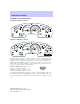
Instrument Cluster Instrument Cluster WARNING LIGHTS AND CHIMES Standard instrument cluster Optional instrument cluster Warning lights and gauges can alert you to a vehicle condition that may become serious enough to cause expensive repairs. A warning light may illuminate when a problem exists with one of your vehicle’s functions. Many lights will illuminate when you start your vehicle to make sure the bulb works.
Instrument Cluster chapter. If the light is blinking, engine misfire is occurring which could damage your catalytic converter. Drive in a moderate fashion (avoid heavy acceleration and deceleration) and have your vehicle serviced immediately. Under engine misfire conditions, excessive exhaust temperatures could damage the catalytic converter, the fuel system, interior floor coverings or other vehicle components, possibly causing a fire.
Instrument Cluster Air bag readiness: If this light fails to illuminate when ignition is turned to ON, continues to flash or remains on, have the system serviced immediately. A chime will also sound when a malfunction in the supplemental restraint system has been detected. Safety belt: Reminds you to fasten your safety belt. A chime will also sound to remind you to fasten your safety belt. Charging system: Illuminates when the battery is not charging properly.
Instrument Cluster Warning Light display Warning light remains on Warning light flashing (flashes for 20 seconds either at start up or while driving) Customer Action • Check your tire pressure and ensure your tires are properly inflated. • If your tires are inflated to the manufacturers recommended air pressure and the light remains on, please have the system inspected immediately by your servicing dealership. • Your spare tire is in use. Repair the road wheel to restore system function.
Instrument Cluster AWD lock (if equipped): Illuminates when all wheel drive (AWD) is locked. If the light continues to flash, have the system serviced. Speed control: Illuminates when the speed control is activated. Turns off when the speed control system is deactivated. Door ajar (if equipped): Illuminates when the ignition is in the ON position and any door is open. AWD LOCK DOOR AJAR Turn signal: Illuminates when the left or right turn signal or the hazard lights are turned on.
Instrument Cluster GAUGES Standard instrument cluster gauges Optional instrument cluster gauges Speedometer: Indicates the current vehicle speed.
Instrument Cluster Engine coolant temperature gauge: Indicates engine coolant temperature. At normal operating temperature, the needle will be in the normal range (between “H” and “C”). If it enters the red section, the engine is overheating. Stop the vehicle as soon as safely possible, switch off the engine and let the engine cool. Never remove the coolant reservoir cap while the engine is running or hot. Odometer: Registers the total kilometers (miles) of the vehicle.
Instrument Cluster Tachometer: Indicates the engine speed in revolutions per minute. Driving with your tachometer pointer continuously at the top of the scale may damage the engine. Battery voltage gauge: Indicates the battery voltage when the ignition is in the ON position. If the pointer moves and stays outside the normal operating range (as indicated by arrows), have the vehicle’s electrical system checked as soon as possible. Engine oil pressure gauge: Indicates engine oil pressure.
Entertainment Systems Entertainment Systems AM/FM STEREO / SINGLE CD RADIO (IF EQUIPPED) 14 15 16 17 18 13 1 2 3 4 6 5 VOL - PUSH ON AM FM SCN ST FM1 BASS TREB BAL FADE CD CLK 12 DISC SEEK EJ TUNE COMP DISCS 11 CD 1 10 CD 2 SHUFFLE 3 9 4 5 6 8 7 / to shift 1. Balance: Press sound to the left/right speakers. / to shift 2. Fade: Press sound to the front/rear speakers. 3. SCN (Scan): Press to hear a brief sampling of all listenable stations or CD tracks.
Entertainment Systems 5. EJ (eject): Press to eject a CD. 6. COMP (Compression): In CD mode, press to bring louder and softer levels into more comfortable listening level. The compression icon (c) will appear in the display. SHUFFLE 7. Shuffle: Press to listen to the 6 tracks on the CD in random order. Press again to turn off. 8. Memory presets: To set a CD CD SHUFFLE 1 2 3 4 5 6 station: Select frequency band AM/FM; tune to a station. Press and hold a preset button until sound returns.
Entertainment Systems 15. AM/FM: Press to choose a frequency band in radio mode. / to 16. Bass: Press increase/decrease the bass output. / to 17. Treble: Press increase/decrease the treble output. 18. CD door: Insert a CD printed side up. DISC CD unit are designed to play commercially pressed 12 cm (4.75 in) audio compact discs only. Due to technical incompatibility, certain recordable and re-recordable compact discs may not function correctly when used in Ford CD players.
Entertainment Systems AUDIOPHILE SATELLITE READY AM/FM STEREO IN-DASH SIX CD RADIO (IF EQUIPPED) 1. Seek: Press and release / for previous/next SEEK strong station, selection or track. 2. Rewind: In CD mode, press until desired selection is reached. Fast forward: In CD mode, press until desired selection is reached. TEXT: TEXT is only available when equipped with Satellite radio. Your Audiophile radio comes equipped with Satellite ready capability.
Entertainment Systems 4. Mute: Press to MUTE playing media; press again to return to playing media. 5. Eject: Press to eject a CD. Press and hold to eject all loaded discs. 6. Bass: Press BASS; then press / to decrease/increase SEL the bass output. Treble: Press TREB; then press / to decrease/increase SEL the treble output. 7. Select: Use with Bass, Treble, Balance and Fade controls, to adjust levels, set the clock, and with Autostore and Autoset functions. 8.
Entertainment Systems FIND Program type: Allows you to search RDS-equipped stations for a certain category of music format: Classic, Country, Info, Jazz, Oldies, R&B, Religious, Rock, Soft, Top 40. Show TYPE: Displays the station’s call letters format. Shuffle: Press to play tracks in a random order. Press MENU until SHUF appears in the display. Use SEL to select SHUF DISC, SHUF TRAC or SHUF OFF. Compression: Brings soft and loud CD passages together for a more consistent listening level.
Entertainment Systems 13. Power/volume: Press to turn ON/OFF; turn to increase or decrease volume levels. Speed sensitive volume: Radio volume changes automatically and slightly with vehicle speed to compensate for road and wind noise. Recommended level is 1–3. Level 0 turns the feature off and level 7 is the maximum setting. Press and hold the volume control for five seconds. Then press SEL to ) or decrease ( ) the volume setting. The level will increase ( appear in the display. 14.
Entertainment Systems For information regarding SIRIUS Satellite Radio, please call toll-free 888-539-SIRIUS (888-539-7474) or visit the SIRIUS website at www.siriusradio.com RADIO FREQUENCIES AM and FM frequencies are established by the Federal Communications Commission (FCC) and the Canadian Radio and Telecommunications Commission (CRTC). Those frequencies are: AM - 530, 540–1700, 1710 kHz FM- 87.7, 87.9–107.7, 107.
Entertainment Systems homemade paper (adhesive) labels should not be inserted into the CD player. The label may peel and cause the CD to become jammed. It is recommended that homemade CDs be identified with permanent felt tip marker rather than adhesive labels. Ballpoint pens may damage CDs. Please contact your dealer for further information. AUDIO SYSTEM WARRANTY AND SERVICE Refer to the Warranty Guide for audio system warranty information. If service is necessary, see your dealer or qualified technician.
Climate Controls Climate Controls MANUAL HEATING AND AIR CONDITIONING SYSTEM (IF EQUIPPED) 1. Temperature selection: Controls the temperature of the airflow in the vehicle. 2. Air flow selections: Controls the direction of the airflow in the vehicle. See the following for a brief description on each control. MAX A/C: Uses recirculated air through the instrument panel registers to cool the vehicle.
Climate Controls To aid in side window defogging/demisting in cold weather: 1. Select 2. Select A/C 3. Modulate the temperature control to maintain comfort. 4. Set the fan speed to HI 5. Direct the outer instrument panel vents towards the side windows To increase airflow to the outer instrument panel vents, close the vents located in the middle of the instrument panel. Do not place objects on top of the instrument panel as these objects may become projectiles in a collision or sudden stop.
Climate Controls 3. Passenger side temperature control: Controls the temperature on the passenger side of the vehicle when in dual zone mode. To enter dual zone, press the passenger temperature control or DUAL. The passenger temperature will appear in the display. 4. Rear defrost control: Removes R ice and fog from the rear windshield. Press to turn on/off. 5.
Climate Controls 14. Driver’s side temperature control: Controls the temperature on the driver side of the vehicle. 15. Fan Speed: Used to manually enable or disable the fan speed. EXT 16. EXT: Displays the outside air temperature. It will remain displayed until the EXT control is pressed again. The external temperature will be most accurate when the vehicle has been moving for a period of time. FC 17.
Climate Controls Do not place objects on top of the instrument panel as these objects may become projectiles in a collision or sudden stop. Auxiliary system (if equipped) Your vehicle may be equipped with auxiliary climate controls. These allow the front or rear seat passengers to control airflow direction, temperature and fan level of the rear compartment to quickly heat or cool the entire vehicle. Front auxiliary controls: 1. Temperature control: Determines temperature level.
Climate Controls 1. Temperature control: 3 1 Determines temperature levels. If the main climate control system is 0 1 2 3 mode, cooling in MAX A/C or 4 the auxiliary controls will not function as the entire vehicle will operate at a full cool temperature. 2. Mode selector: Press to select 2 (Floor) between air flow to or (Panel). Directs air to the floor of the third row seating. directs air to the overhead registers of the second and third row seating.
Lights Lights HEADLAMP CONTROL Turns the lamps off. Turns on the parking lamps, instrument panel lamps, license plate lamps and tail lamps. A Turns the headlamps on. Autolamp system The autolamp system sets the headlamps to turn on and off automatically. The autolamp control, located on the headlamp control, may be set to: • turn on the lamps automatically at night • turn off the lamps automatically during the daylight • keep the lamps on for up to three minutes after the key is turned to OFF.
Lights Always remember to turn on your headlamps at dusk or during inclement weather. The Daytime Running Light (DRL) System does not activate your tail lamps and generally may not provide adequate lighting during these conditions. Failure to activate your headlamps under these conditions may result in a collision. High beams Push the lever toward the instrument panel to activate. Pull the lever towards you to deactivate. OFF Flash to pass Pull the lever toward you to activate.
Lights Move the control to the full down position (past detent) to prevent interior lamps from illuminating when the doors are opened. AIMING THE HEADLAMPS The headlamps on your vehicle are properly aimed before leaving the assembly plant. If your vehicle is involved in an accident or if you have problems fixing the alignment of your headlamps, have them checked by a qualified service technician. Headlamp aim adjustment The headlamps on your vehicle can only be vertically adjusted.
Lights 5. Locate the vertical adjuster for each headlamp. Adjust the aim by turning the adjuster control either clockwise (to adjust down) or counterclockwise (to adjust up). Note: Use a 4 mm socket or box wrench to turn the vertical adjuster control. 6. Horizontal aiming is not required for this vehicle and is non-adjustable. TURN SIGNAL CONTROL • Push down to activate the left turn signal. • Push up to activate the right turn signal.
Lights Cargo/reading lamps The dome portion of the lamp or the center light can be turned on when the headlamp control is rotated fully up or when a door is opened. With the ignition in the ACC or ON position, the rear dome lamp can be turned ON or OFF by sliding the control. BULBS Replacing exterior bulbs Check the operation of all the bulbs frequently. Replacing the interior bulbs Check the operation of the bulbs frequently. To replace any of the interior bulbs, see a dealer or qualified technician.
Lights Using the right bulbs Replacement bulbs are specified in the chart below. Headlamp bulbs must be marked with an authorized “D.O.T.” for North America and an “E” for Europe to assure lamp performance, light brightness and pattern and safe visibility. Using incorrect bulbs may damage the lamp assembly or void the lamp assembly warranty or may not provide quality bulb burn time.
Lights Replacing headlamp bulbs Do not touch the glass of a halogen bulb. 1. Turn off the headlamps and open the hood. 2. Remove two retainer pins, then pull headlamp forward. 3. Disconnect the electrical connector. 4. Remove the bulb retaining ring.
Lights 5. Carefully pull old bulb out of the lamp assembly Handle a halogen headlamp bulb carefully and keep out of children’s reach. Grasp the bulb only by its plastic base and do not touch the glass. The oil from your hand could cause the bulb to break the next time the headlamps are operated. Reverse steps to reinstall bulb(s). Replacing front parking/turn signal bulbs 1. Turn OFF the headlamps and open the hood. 2. Remove the two headlamp retainer pins, then pull headlamp forward.
Lights 3. Remove the bulb socket from the lamp assembly. 4. Carefully pull old bulb out of the lamp assembly Reverse steps to reinstall bulb(s). Replacing side repeater bulbs 1. Turn the headlamp switch to off. 2. Carefully pry the lamp assembly away from the fender. 3. Rotate the bulb socket counterclockwise to remove it from the lamp assembly. 4. Pull the bulb straight out. Reverse steps to reinstall bulb(s).
Lights Replacing front/rear side marker bulbs 1. Turn the headlamp switch to off. 2. Reach under the bumper and rotate the bulb socket counterclockwise to remove it. 3. Pull the bulb straight out. Reverse steps to reinstall bulb(s). Replacing tail/brake/turn/backup lamp bulbs 1. Turn the headlamp switch to OFF and open the liftgate. 2. Remove the two screws from the lamp assembly. 3. Remove the lamp assembly. 4. Rotate the bulb socket counterclockwise and remove it from the lamp assembly. 5.
Lights Replacing license plate lamp bulbs 1. Make sure the headlamp switch is in the OFF position and then remove two screws and the license plate lamp assembly. 2. Remove the bulb socket from the lamp assembly by turning counterclockwise and pull the bulb straight out. Reverse steps to reinstall bulb(s). Replacing high-mount brakelamp bulb 1. Remove the two screws and lamp assembly from vehicle. 2. Remove the bulb socket from the lamp assembly by depressing the snaps and pull the bulb straight out.
Driver Controls Driver Controls MULTI-FUNCTION LEVER Windshield wiper: Rotate the end of the control away from you to increase the speed of the wipers; rotate towards you to decrease the OFF speed of the wipers. Speed dependent wipers: When the wiper control is on, the speed of the wipers will automatically adjust with the vehicle speed. The faster your vehicle is travelling the faster the wipers will go.
Driver Controls Changing the wiper blades 1. Pull the wiper arm away from the vehicle. Turn the blade at an angle from the wiper arm. Push the lock pin manually to release the blade and pull the wiper blade down toward the windshield to remove it from the arm. 2. Attach the new wiper to the wiper arm and press it into place until a click is heard. 3. Replace wiper blades every 6 months for optimum performance. TILT STEERING COLUMN Pull the lever down to unlock the steering column.
Driver Controls CENTER CONSOLE Your vehicle may be equipped with a variety of console features. These include: • Utility compartment with cassette/compact disc storage • Auxiliary power point • Cupholders • Tissue box holder (located on underside of console lid) • Ash tray (if equipped) The rear side of the console may incorporate the following features: • air vents • cupholders (will pull up with break away feature) • rear power point Use only soft cups in the cupholder.
Driver Controls Rear center console features (if equipped) The rear center console incorporates the following features: • Utility compartment • Cupholders • Removable tray • Flip forward armrest to provide a flat load floor OVERHEAD CONSOLE (IF EQUIPPED) The appearance of your vehicle’s overhead console will vary according to your option package. Storage compartment Press the latch to open the storage compartment.
Driver Controls Installing a garage door opener (if equipped) The storage compartment can be converted to accommodate a variety of aftermarket garage door openers: • Place the Velcro hook onto the side of the aftermarket transmitter opposite of the button. • Place the transmitter into storage compartment, button down. • Place the provided height adaptors onto the back of the door as needed. • Close the door. • Press the depression in the door to activate the transmitter.
Driver Controls Illuminated visor mirror To turn on the visor mirror lamps, lift the mirror cover. AUXILIARY POWER POINT Power point outlets are designed for accessory use only. Do not hang any type of accessories or accessory bracket from their plugs. Improper use of the power point outlet can cause damage not covered by your warranty. Do not plug electrical accessories into the cigarette lighter socket (if equipped). Always use the power point for accessories.
Driver Controls POWER WINDOWS When closing the power windows, you should verify they are free of obstructions and ensure that children and/or pets are not in the proximity of the window openings. Press and hold the bottom part of the rocker switch to open the window. Press and hold the top part of the rocker switch to close the window. One touch down Allows the driver’s window to open fully without holding the control down. Press completely down on AUTO and release quickly. Press again to stop.
Driver Controls POWER SIDE VIEW MIRRORS The ignition must be in the ACC or ON position to adjust the power side view mirrors. To adjust your mirrors: 1. Rotate the control clockwise to adjust the right mirror and rotate the control counterclockwise to adjust the left mirror. 2. Move the control in the direction you wish to tilt the mirror. 3. Return to the center position to lock mirrors in place.
Driver Controls POWER ADJUSTABLE FOOT PEDALS (IF EQUIPPED) The accelerator and brake pedal should only be adjusted when the vehicle is stopped and the gearshift lever is in the P (Park) position. Press and hold the rocker control to adjust accelerator and brake pedal toward you or away from you. The adjustment allows for approximately 71 mm (3 inches) of maximum travel. Never adjust the accelerator and brake pedal with feet on the pedals while the vehicle is moving.
Driver Controls 3. Press the SET + control and release it. 4. Take your foot off the accelerator pedal. RES SET + on the 5. The indicator light instrument cluster will turn on. COAST Note: • Vehicle speed may vary momentarily when driving up and down a steep hill. • If the vehicle speed increases above the set speed on a downhill, you may want to apply the brakes to reduce the speed.
Driver Controls Increasing speed while using speed control There are two ways to set a higher speed: RES • Press and hold the SET + control until you get to the desired SET speed, then release the control. + You can also use the SET + COAST control to operate the Tap-Up function. Press and release this control to increase the vehicle set speed in small amounts by 1.6 km/h (1 mph). • Use the accelerator pedal to get to the desired speed.
Driver Controls Turning off speed control There are two ways to turn off the speed control: • Depress the brake pedal. This will not erase your vehicle’s previously set speed. • Press the speed control OFF control. Note: When you turn off the speed control or the ignition, your speed control set speed memory is erased. STEERING WHEEL CONTROLS (IF EQUIPPED) These controls allow you to operate some radio and climate control features.
Driver Controls In AM, FM1, or FM2 mode: • Press MEM to select preset stations within the selected radio band. In CD mode: • Press MEM to select the next selection on the CD. In any mode: • Press VOL + or − to adjust volume. Climate control features Press TMP + or - to adjust temperature. Press + or - to adjust fan speed.
Driver Controls MOON ROOF (IF EQUIPPED) You can move the glass panel of the moon roof back to open or tilt up to ventilate the vehicle. To open the moon roof: The moon roof is equipped with an automatic, one-touch, express opening feature. Press and release the rear portion of the control. To stop motion at any time during the one-touch opening, press the control a second time. To close the moon roof: Press and hold the front portion of the control until the glass panel stops moving.
Driver Controls When programming your HomeLink威 Wireless Control System to a garage door or gate, be sure that people and objects are out of the way to prevent potential harm or damage. Do not use the HomeLink威 Wireless Control System with any garage door opener that lacks safety stop and reverse features as required by U.S. federal safety standards (this includes any garage door opener model manufactured before April 1, 1982).
Driver Controls 3. Simultaneously press and hold both the HomeLink威 and hand-held transmitter button. Do not release the buttons until step 4 has been completed. Some entry gates and garage door openers may require you to replace step 3 with procedures noted in the “Gate Operator and Canadian Programming” section for Canadian residents. 4. The red light will flash slowly and then rapidly. Release both buttons when the red light flashes rapidly.
Driver Controls Gate Operator & Canadian Programming During programming, your hand-held transmitter may automatically stop transmitting — not allowing enough time for HomeLink威 to accept the signal from the hand-held transmitter. After completing steps 1 and 2 outlined in the “Programming” section, replace step 3 with the following: Note: If programming a garage door opener or gate operator, it is advised to unplug the device during the “cycling” process to prevent overheating.
Driver Controls Erasing HomeLink姞 buttons To erase the three programmed buttons (individual buttons cannot be erased): • Press and hold the two outer HomeLink威 buttons until the red indicator light begins to flash-after 20 seconds. Release both buttons. Do not hold for longer that 30 seconds. HomeLink威 is now in the train (or learning) mode and can be programmed at any time beginning with step 2 in the “Programming” section.
Driver Controls Compass The compass reading may be affected when you drive near large buildings, bridges, power lines and powerful broadcast antennas. Magnetic or metallic objects placed in, on or near the vehicle may also affect compass accuracy. Usually, when something affects the compass readings, the compass will correct itself after a few days of operating your vehicle in normal conditions. If the compass still appears to be inaccurate, a manual calibration may be necessary.
Driver Controls Compass calibration adjustment Perform this adjustment in an open area free from steel structures and high voltage lines: For optimum calibration, turn off all electrical accessories (heater/air conditioning, wipers, etc.) and make sure all vehicle doors are shut. 1. Start the vehicle. 2. Locate compass sensor mounted at base of mirror. 3. Press the button on the top of the compass module until ZONE appears in the instrument cluster display.
Driver Controls Selectable features Reset Press this control to select and reset functions shown in the INFO menu and SETUP menu. Info menu This control displays the following control displays: • Odometer/Compass • Trip odometer/Odometer/Compass • Average Fuel Economy • Trip Elapsed Drive Time • Distance to Empty Odometer/Trip odometer Refer to Gauges in the Instrument Cluster chapter.
Driver Controls degrees between adjacent zones and will become noticeable as the vehicle crosses multiple zones. A correct zone setting will eliminate this error. Refer to Compass zone/calibration adjustment. Compass zone/calibration adjustment Perform this adjustment in an open area free from steel structures and high voltage lines. For optimum calibration, turn off all electrical accessories (heater/air conditioning, wipers, etc.) and make sure all vehicle doors are shut. 1.
Driver Controls 9. Slowly drive the vehicle in a circle (less than 5 km/h [3 mph]) until the CIRCLE SLOWLY TO CALIBRATE indicator changes to CALIBRATION COMPLETED. This will take up to three circles to complete calibration. 10. The compass is now calibrated. Average fuel economy (AFE) Select this function from the INFO menu to display your average fuel economy in liters/100 km or miles/U.S. gallon.
Driver Controls Trip elapsed drive time Select this function from the INFO menu to display a timer. To operate the Trip Elapsed Drive Time perform the following: 1. Press and release RESET in order to start the timer. 2. Press and release RESET to pause the timer. 3. Press and hold RESET for 2 seconds in order to reset the timer.
Driver Controls System check Selecting this function from the SETUP menu causes the message center to cycle through each of the systems being monitored. For each of the monitored systems, the message center will indicate either an OK message or a warning message for three seconds. Pressing the RESET control cycles the message center through each of the systems being monitored. The sequence of the system check report and how it appears in the message center is as follows: 1. FUEL LEVEL 2.
Driver Controls Easy entry/exit (if equipped) 1. Select this function from the SETUP control for the current display mode. 2. Press the RESET control to turn the easy entry/exit feature ON or OFF. For more information refer to Memory Seat and Pedals in the Seating and Safety Restraints chapter. Autolamp delay 1. Select this function from the SETUP control for the current display mode. 2. Press the RESET control to select the autolamp delay time. Language 1.
Driver Controls 1. Press the SETUP control for the current display mode. 2. Press the RESET control within 4 seconds to turn the AWD system to the LOCKED mode. System warnings System warnings alert you to possible problems or malfunctions in your vehicle’s operating systems. In the event of a multiple warning situation, the message center will cycle the display to show all warnings by displaying each one for several seconds.
Driver Controls Warning display Status Check engine temperature Warning returns after 10 minutes Transmission overheated Check transmission Low fuel level Check fuel cap Check charging system Low brake fluid level Low oil pressure Warning-tire very low (if equipped) ETC-engine failsafe mode AWD disabled lock (vehicles equipped with AdvanceTrac娂 only) Check tire pressure (if Warning returns after the ignition key equipped) is turned from OFF to ON.
Driver Controls AWD LOCK OFF and AWD AUTO ON (vehicles equipped with AdvanceTrac娂 only). Displayed when the AWD system is completely cooled down from being overheated. CHECK ENGINE TEMPERATURE. Displayed when the engine coolant is overheating. Stop the vehicle as soon as safely possible, turn off the engine and let it cool. Check the coolant and coolant level. Refer to Engine coolant in the Maintenance and specifications chapter.
Driver Controls LOW OIL PRESSURE. Displayed when the engine oil level is low. If this warning message is displayed, check the level of the engine oil. Refer to Engine oil in the Maintenance and specifications chapter for information about adding engine oil. WARNING-TIRE VERY LOW (if equipped). Displayed when one or more tires have very low pressure.
Driver Controls CHANGE OIL SOON/OIL CHANGE REQUIRED. Displayed when the engine oil life remaining is 5 percent or less. When oil life left is between 5% and 0%, the CHANGE OIL SOON message will be displayed. When oil life left reaches 0%, the OIL CHANGE REQUIRED message will be displayed. An oil change is required whenever indicated by the message center. USE ONLY RECOMMENDED ENGINE OILS.
Driver Controls 2. Press and release the RESET control to display “OIL LIFE XX% HOLD RESET NEW”. 3. Press and hold the RESET control for 2 seconds to display “IF NEW OIL HOLD RESET”. 4. Release the RESET control momentarily, then press RESET and SETUP controls at the same time to activate a service mode which will display “OIL LIFE XX% RESET TO ALTER”. 5. Press RESET until you find your personalized “OIL LIFE XX%”. 6.
Driver Controls POSITIVE RETENTION FLOOR MAT Position the driver floor mat so that the eyelet is over the pointed end of the retention post and rotate forward to lock in. Make sure that the mat does not interfere with the operation of the accelerator or the brake pedal. To remove the floor mat, reverse the installation procedure. REAR LIFTGATE The liftgate area is only intended for cargo, not passengers. You can open and close the liftgate from outside the vehicle.
Driver Controls Make sure the liftgate door and/or window are closed to prevent exhaust fumes from being drawn into the vehicle. This will also reduce the risk of passengers and cargo falling out. CARGO COVER (IF EQUIPPED) Your vehicle may be equipped with a cargo area cover that covers the luggage compartment of your vehicle. To install the cover: Push both ends of the cover into the depressions (right side first) in the trim panels behind the second row seat.
Driver Controls 5 passenger stowage: When the lid is open, it will stand up on its own. The lid can be detached from the vehicle and used as a knee pad (carpet side up) for changing a tire. 1. To open, lift the release handle and the lid. 2. To close, lower the lid, lift the release handle and press down on the lid. LUGGAGE RACK The maximum recommended load is 90 kg (200 lbs), evenly distributed. If it is not possible to distribute the load, position it as far rearward as possible.
Driver Controls Vehicles with a higher center of gravity such as utility and four-wheel drive vehicles handle differently than vehicles with a lower center of gravity. Utility and four-wheel drive vehicles are not designed for cornering at speeds as high as passenger cars any more than low-slung sport cars are designed to perform satisfactorily under off-road conditions. Avoid sharp turns, excessive speed and abrupt maneuvers in these vehicles.
Locks and Security Locks and Security KEYS One key operates all the locks and starts the vehicle. Always carry a spare key with you in case of an emergency. Your keys are programmed to your vehicle; using a non-programmed key will not permit your vehicle to start. If you lose your dealer supplied keys, replacement keys are available through your authorized dealer. Refer to SecuriLock娂 Passive Anti-Theft System for more information. POWER DOOR LOCKS Press control to unlock all vehicle doors.
Locks and Security Childproof door locks • When these locks are set, the rear doors cannot be opened from the inside. • The rear doors can be opened from the outside when the doors are unlocked. The childproof locks are located on rear edge of each rear door and must be set separately for each door. Setting the lock for one door will not automatically set the lock for both doors. • Move lock control up to engage the childproof lock. • Move control down to disengage childproof locks.
Locks and Security If there is any potential remote keyless entry problem with your vehicle, ensure ALL remote entry transmitters are brought to the dealership, to aid in troubleshooting. Unlocking the doors 1. Press and release to unlock the driver’s door. Note: The interior lamps will illuminate. and release again within three seconds to unlock all the 2. Press doors. The remote entry system activates the illuminated entry feature.
Locks and Security Memory seats/adjustable pedals/easy entry-exit feature (if equipped) The remote entry system can also control the memory seat /adjustable pedals/easy entry-exit feature. Press to automatically move the seat and adjustable pedals to the desired memory position (the seat position corresponds to the transmitter being used). Activating the memory seat feature To activate this feature: 1. Position the seat and adjustable pedals to the position desired. 2.
Locks and Security • other vehicles parked next to the vehicle. To replace the battery: 1. Twist a thin coin between the two halves of the remote entry transmitter near the key ring. DO NOT TAKE THE RUBBER COVER AND CIRCUIT BOARD OFF THE FRONT HOUSING OF THE REMOTE ENTRY TRANSMITTER. 2. Do not wipe off any grease on the battery terminals on the back surface of the circuit board. 3. Remove the old battery. 4. Insert the new battery.
Locks and Security To reprogram the remote entry transmitters: 3 2 4 1 1. Ensure the vehicle is electronically unlocked. 2. Put the key in the ignition. 3. Turn the key from the 1 (LOCK) position to 3 (ON). 4. Cycle eight times rapidly (within 10 seconds) between the 1 (LOCK) position and 3 (ON). Note: The eighth turn must end in the 3 (ON) position. 5. The doors will lock, then unlock, to confirm that the programming mode has been activated. 6.
Locks and Security The inside lights will not turn off if: • they have been turned on with the dimmer control, or • any door is open. The battery saver will shut off the interior lamps 10 minutes after the ignition has been turned to the OFF position. KEYLESS ENTRY SYSTEM (IF EQUIPPED) You can use the keyless entry keypad to: • lock or unlock the doors without using a key. • open the liftgate window. • activate or deactivate the autolock feature.
Locks and Security • The factory set code will work even if you have set your own personal code. • If you set a second personal code it will erase your first personal code. Erasing personal code 1. Enter the factory set 5–digit code. 2. Within five seconds, press the 1 • 2 on the keypad and release. 3. Press and hold the 1 • 2 for two seconds. This must be done within five seconds of completing step 2. Your personal code is now erased and only the factory set 5–digit code will work.
Locks and Security • • • • all the doors, the liftgate and liftgate window are closed, the ignition is in the ON position, you shift into any gear putting the vehicle in motion, and the brake pedal is released and the vehicle attains a speed greater than 8 km/h (5 mph).
Locks and Security Keyless entry key pad procedure 1. Turn the ignition to the OFF position. 2. Close all the doors, the liftgate and liftgate window. 3. Enter 5–digit entry code 4. Press and hold the 7 • 8. While holding the 7 • 8 press the 3 • 4. 5. Release the 3 • 4. 6. Release the 7 • 8. The user should receive a horn chirp to indicate the system has been disabled or a chirp followed by a honk to indicate the system has been enabled.
Locks and Security Theft indicator The theft indicator is located on top of the instrument panel. • When the ignition is in the OFF position, the indicator will flash once every 2 seconds to indicate the SecuriLock娂 system is functioning as a theft deterrent. • When the ignition is in the ON position, the indicator will glow for 3 seconds to indicate normal system functionality.
Locks and Security Programming spare keys You can program your own coded keys to your vehicle. Tips: • A maximum of eight keys can be coded to your vehicle. • Only use Securilock娂 keys. • You must have two previously programmed coded keys (keys that already operate your vehicle’s engine) and the new unprogrammed key(s) readily accessible. • If two previously programmed coded keys are not available, you must take your vehicle to your dealer to have the spare key(s) programmed.
Locks and Security 9. Remove the newly programmed coded key from the ignition. If the key has been successfully programmed it will start the vehicle’s engine and the theft indicator light will illuminate for three seconds and then go out. If the key was not successfully programmed, it will not start your vehicle’s engine and the theft indicator light will flash on and off, and you may repeat Steps 1 through 5. If failure repeats, bring your vehicle to your dealer to have the new key(s) programmed.
Seating and Safety Restraints Seating and Safety Restraints SEATING Notes: Reclining the seatback can cause an occupant to slide under the seat’s safety belt, resulting in severe personal injuries in the event of a collision. Do not pile cargo higher than the seatbacks to reduce the risk of injury in a collision or sudden stop. Adjustable head restraints Head restraints help to limit head motion in the event of a rear collision. The seats in your vehicle may have adjustable head restraints.
Seating and Safety Restraints Push control to lower head restraint. Adjusting the front manual seat (if equipped) Never adjust the driver’s seat or seatback when the vehicle is moving. Always drive and ride with your seatback upright and the lap belt snug and low across the hips. Lift handle to move seat forward or backward. Pull lever up to adjust seatback.
Seating and Safety Restraints Adjusting the front power seat (if equipped) The control is located on the outboard side of the seat cushion. Press front to raise or lower the front portion of the seat cushion. Press rear to raise or lower the rear portion of the seat cushion. Press the control to move the seat forward, backward, up or down.
Seating and Safety Restraints Memory seat/easy entry/exit feature (if equipped) This system allows automatic positioning of the driver seat to three programmable positions. SET The memory seat control is located on the driver door. • To program position one, move the driver seat to the desired 1 2 position using the seat controls. Press the SET control. The SET control indicator light will briefly illuminate. While the light is illuminated, press control 1.
Seating and Safety Restraints Using the manual lumbar support (if equipped) For more lumbar support, turn the lumbar support control toward the front of vehicle. For less lumbar support, turn the lumbar support control toward the rear of vehicle. Heated seats (if equipped) To operate the heated seats: • Push control located on the seat to activate. • Push again to deactivate. The heated seat icon in the dual electronic automatic temperature control (DEATC) will illuminate when activated.
Seating and Safety Restraints 1. Pull upward on the release handle to cycle the seats to the load-floor position. 2. Rotate the seatback downward into the load floor position. 3. Press down on the top outboard area of the seatback until a click is heard. The seat is now latched in the floor position. To return the seat to the upright position: • Pull the release handle upward to unlatch the seat. • Rotate the seatback upward until the seatback latches in the upright position.
Seating and Safety Restraints Reclining the seatback can cause an occupant to slide under the seat’s safety belt, resulting in severe personal injuries in the event of a collision. Operating the 2nd row seat for E-Z Entry (if equipped) The E-Z Entry seat allows for easier entry and exit to and from the 3rd row seat. To enter the 3rd row seat: 1. Fold down the 2nd row seat. 2. Push the handle all the way forward until the seat releases from the floor. 3. Push the seat upward and fold away from the third row.
Seating and Safety Restraints To exit the 3rd row seat, pull the red access control lever up releasing the seat from the floor and rotate the seat up towards the front seat. Always latch the vehicle seat to the floor, whether the seat is occupied or empty. If not latched, the seat may cause injury during a sudden stop. Folding the middle 2nd row seat (If equipped) To fold the seatback down: 1. Locate the lever on the top left of the seatback. 2.
Seating and Safety Restraints To return the seatback to the upright position: 1. Pull the lever and lift the seatback toward the rear of the vehicle. 2. Rotate the seatback until you hear a click, locking it in the upright position. Second row center seat storage space (if equipped) Storage space is provided underneath the 40/20/40 second row center seat. To access the storage space pull up on the strap.
Seating and Safety Restraints To put seat in stowed position: 1. Pull the seat release lever located on top of the seatback while pushing the seatback down onto the seat cushion. 2. The seatback will latch into place. 3. Push the closeout panel forward over the space between the seats. To put seat in upright position: 1. Pull back the slider panel on the seatback to release the closeout panel.
Seating and Safety Restraints 2. Pull the seat release lever located on top of the seatback while lifting the seatback into the upright position. 3. The seatback will latch into place. The third row seat is equipped with combination lap and shoulder belts in both seating positions. For information on the proper operation of the safety restraints, refer to Safety Restraints in this chapter.
Seating and Safety Restraints information to the Restraints Control Module (RCM). During a crash, the RCM activates the safety belt pretensioners and/or either one or both stages of the dual-stage air bag supplemental restraints based on crash severity and occupant conditions. The fact that the pretensioners or air bags did not activate for both front seat occupants in a collision does not mean that something is wrong with the system.
Seating and Safety Restraints occupant’s body during a collision. This maximizes the effectiveness of the safety belts and helps properly position the occupant relative to the air bag to improve protection. The safety belt pretensioners can be either activated alone or, if the collision is of sufficient severity, together with the air bags.
Seating and Safety Restraints To reduce the risk of injury, make sure children sit where they can be properly restrained. Never let a passenger hold a child on his or her lap while the vehicle is moving. The passenger cannot protect the child from injury in a collision. All occupants of the vehicle, including the driver, should always properly wear their safety belts, even when an air bag (SRS) is provided. It is extremely dangerous to ride in a cargo area, inside or outside of a vehicle.
Seating and Safety Restraints Energy Management Feature • This vehicle has a safety belt system with an energy management feature at the front seating positions to help further reduce the risk of injury in the event of a head-on collision. • This safety belt system has a retractor assembly that is designed to extend the seat belt webbing in a controlled manner. This helps reduce the belt force acting on the user’s chest.
Seating and Safety Restraints • Front and rear seats All safety restraints in the vehicle are combination lap and shoulder belts. All of the passenger combination lap and shoulder belts have two types of locking modes described below: Vehicle sensitive mode This is the normal retractor mode, which allows free shoulder belt length adjustment to your movements and locking in response to vehicle movement.
Seating and Safety Restraints How to use the automatic locking mode • Buckle the combination lap and shoulder belt. • Grasp the shoulder portion and pull downward until the entire belt is pulled out. • Allow the belt to retract. As the belt retracts, you will hear a clicking sound. This indicates the safety belt is now in the automatic locking mode.
Seating and Safety Restraints After any vehicle collision, the combination lap and shoulder belt system at all passenger seating positions must be checked by a qualified technician to verify that the “automatic locking retractor” feature for child seats is still functioning properly, in addition to other checks for proper seat belt system function.
Seating and Safety Restraints Safety belt height adjustment Your vehicle has safety belt height adjustments for the front and second row outboard seating positions. Adjust the height of the shoulder belt so the belt rests across the middle of your shoulder. To adjust the shoulder belt height, squeeze the button and slide the height adjuster up or down. Release the button and pull down on the height adjuster to make sure it is locked in place.
Seating and Safety Restraints Conditions of operation If... The driver’s safety belt is not buckled before the ignition switch is turned to the ON position... The driver’s safety belt is buckled while the indicator light is illuminated and the warning chime is sounding... The driver’s safety belt is buckled before the ignition switch is turned to the ON position... Then... The safety belt warning light illuminates 1-2 minutes and the warning chime sounds 4-8 seconds.
Seating and Safety Restraints If... The driver’s safety belt is buckled before the ignition switch is turned to the ON position... Then... The BeltMinder feature will not activate. The following are reasons most often given for not wearing safety belts: (All statistics based on U.S. data) Reasons given... “Crashes are rare events” “I’m not going far” “Belts are uncomfortable” “I was in a hurry” “Safety belts don’t work” “Traffic is light” “Belts wrinkle my clothes” Consider...
Seating and Safety Restraints Reasons given... “The people I’m with don’t wear belts” “I have an air bag” “I’d rather be thrown clear” Consider... Set the example, teen deaths occur 4 times more often in vehicles with TWO or MORE people. Children and younger brothers/sisters imitate behavior they see. Air bags offer greater protection when used with safety belts. Frontal airbags are not designed to inflate in rear and side crashes or rollovers. Not a good idea.
Seating and Safety Restraints BeltMinder deactivation/activation procedure To reduce the risk of injury, do not deactivate/activate the Belt Minder feature while driving the vehicle. 1. Turn the ignition switch to the RUN (or ON) position. (DO NOT START THE ENGINE) 2. Wait until the safety belt warning light turns off. (Approximately 1–2 minutes) • Steps 3–5 must be completed within 60 seconds or the procedure will have to be repeated. 3.
Seating and Safety Restraints assemblies, buckle support assemblies (slide bar-if equipped), shoulder belt height adjusters (if equipped), shoulder belt guide on seatback (if equipped), child safety seat LATCH and tether anchors, and attaching hardware, should be inspected after a collision. Ford Motor Company recommends that all safety belt assemblies in use in vehicles involved in a collision be replaced.
Seating and Safety Restraints Important SRS precautions The SRS is designed to work with the safety belt to help protect the driver and right front passenger from certain upper body injuries. Air bags DO NOT inflate slowly; there is a risk of injury from a deploying air bag. All occupants of the vehicle, including the driver, should always properly wear their safety belts, even when an air bag (SRS) is provided.
Seating and Safety Restraints Do not attempt to service, repair, or modify the air bag supplemental restraint systems or its fuses. See your Ford or Lincoln Mercury dealer. Modifications to the front end of the vehicle, including frame, bumper, front end body structure and non-Ford tow hooks may effect the performance of the air bag sensors increasing the risk of injury. Do not modify the front end of the vehicle with anything other than authorized Ford accessories for your vehicle.
Seating and Safety Restraints How does the air bag supplemental restraint system work? The air bag SRS is designed to activate when the vehicle sustains longitudinal deceleration sufficient to cause the sensors to close an electrical circuit that initiates air bag inflation. The fact that the air bags did not inflate in a collision does not mean that something is wrong with the system. Rather, it means the forces were not of the type sufficient to cause activation.
Seating and Safety Restraints Several air bag system components get hot after inflation. Do not touch them after inflation. If the air bag has deployed, the air bag will not function again and must be replaced immediately. If the air bag is not replaced, the unrepaired area will increase the risk of injury in a collision. The SRS consists of: • driver and passenger air bag modules (which include the inflators and air bags). • Safety canopy娂 system (if equipped).
Seating and Safety Restraints Safety Canopy姟 system (if equipped) Do not place objects or mount equipment on or near the headliner at the siderail that may come into contact with a deploying Safety Canopy娂. Failure to follow these instructions may increase the risk of personal injury in the event of a collision. Do not lean your head on the door. The Safety Canopy娂 could injure you as it deploys from the headliner.
Seating and Safety Restraints How does the Safety Canopy姟 system work? The design and development of the Safety Canopy娂 system included recommended testing procedures that were developed by a group of automotive safety experts known as the Side Airbag Technical Working Group. These recommended testing procedures help reduce the risk of injuries related to the deployment of side airbags (including the Safety Canopy娂).
Seating and Safety Restraints The Safety Canopy娂 is mounted to the roof side-rail sheet metal, behind the headliner, above the first and second row seats. In certain lateral collisions or rollover events, the Safety Canopy娂 system will be activated, regardless of which seats are occupied. The Safety Canopy娂 is designed to inflate between the side window area and occupants to further enhance protection provided in side impact collisions and rollover events.
Seating and Safety Restraints Any difficulty with the system is indicated by one or more of the following: • The readiness light (same light as for front air bag system) will either flash or stay lit. • The readiness light will not illuminate immediately after ignition is turned on. • A series of five beeps will be heard. The tone pattern will repeat periodically until the problem and light are repaired.
Seating and Safety Restraints Children and safety belts If the child is the proper size, restrain the child in a safety seat. Children who are too large for child safety seats (as specified by your child safety seat manufacturer) should always wear safety belts. Follow all the important safety restraint and air bag precautions that apply to adult passengers in your vehicle.
Seating and Safety Restraints Booster seats should be used until you can answer YES to ALL of these questions: • Can the child sit all the way back against the vehicle seat back with knees bent comfortably at the edge of the seat without slouching? • Does the lap belt rest low across the hips? • Is the shoulder belt centered on the shoulder and chest? • Can the child stay seated like this for the whole trip? Types of booster seats There are two types of belt-positioning booster seats: • Those that are back
Seating and Safety Restraints The shoulder belt should cross the chest, resting snugly on the center of the shoulder. The lap belt should rest low and snug across the hips, never up high across the stomach. If the booster seat slides on the vehicle seat, placing a rubberized mesh sold as shelf or carpet liner under the booster seat may improve this condition. The importance of shoulder belts Using a booster without a shoulder belt increases the risk of a child’s head hitting a hard surface in a collision.
Seating and Safety Restraints safety seat you put in your vehicle. If you do not install and use the safety seat properly, the child may be injured in a sudden stop or collision. When installing a child safety seat: • Review and follow the information presented in the Air bag supplemental restraint system (SRS) section in this chapter. • Use the correct safety belt buckle for that seating position (the buckle closest to the direction the tongue is coming from).
Seating and Safety Restraints Rear-facing child seats or infant carriers should never be placed in the front seats. Installing child safety seats with combination lap and shoulder belts Air bags can kill or injure a child in a child seat. NEVER place a rear-facing child seat in front of an active air bag. If you must use a forward-facing child seat in the front seat, move the seat all the way back. Children 12 and under should be properly restrained in the rear seat whenever possible. 1.
Seating and Safety Restraints 3. While holding the shoulder and lap belt portions together, route the tongue through the child seat according to the child seat manufacturer’s instructions. Be sure the belt webbing is not twisted. 4. Insert the belt tongue into the proper buckle (the buckle closest to the direction the tongue is coming from) for that seating position until you hear a snap and feel the latch engage. Make sure the tongue is latched securely by pulling on it. 5.
Seating and Safety Restraints 7. Pull the lap belt portion across the child seat toward the buckle and pull up on the shoulder belt while pushing down with your knee on the child seat. 8. Allow the safety belt to retract to remove any slack in the belt. 9. Before placing the child in the seat, forcibly move the seat forward and back to make sure the seat is securely held in place. To check this, grab the seat at the belt path and attempt to move it side to side and forward.
Seating and Safety Restraints • 5 passenger vehicle For the center seat, use either of the two tether anchors/cargo tie-downs in the scuff plate along the back edge of the floor. • 7 passenger vehicle Attach the tether strap only to the appropriate tether anchor as shown. The tether strap may not work properly if attached somewhere other than the correct tether anchor. 1. Position the child safety seat on the rear seat cushion. 2.
Seating and Safety Restraints • Behind 2nd row seat • At the rear of the cargo area 133 2004 Mountaineer (mnt) Owners Guide (post-2002-fmt) USA English (fus)
Seating and Safety Restraints 4. Clip the tether strap to the anchor. If the tether strap is clipped incorrectly, the child safety seat may not be retained properly in the event of a collision. 5. Install the child safety seat tightly using the LATCH anchors or safety belts. Follow the instructions in this chapter. 6. Tighten the child safety seat tether strap according to the manufacturer’s instructions.
Seating and Safety Restraints Your vehicle has LATCH anchors for child seat installation at the seating positions marked with the child seat symbol: Never attach two LATCH child safety seats to the same anchor. In a crash, one anchor may not be strong enough to hold two child safety seat attachments and may break, causing serious injury or death. The lower anchors for child seat installation are located at the rear section of the second row seat between the cushion and seat back.
Seating and Safety Restraints Follow the child seat manufacturer’s instructions to properly install a child seat with LATCH attachments. Two plastic LATCH guides can be obtained at no charge from any Ford or Lincoln-Mercury dealer. They snap onto the LATCH lower anchors in the seat to help attach a child seat with rigid attachments. The guides hold the seat trim away to expose the anchor and make it easier to attach some child seats.
Driving Driving STARTING Positions of the ignition 1. OFF/LOCK, shuts off the engine 3 and all accessories/locks the steering wheel, gearshift lever and allows key 2 removal. 4 2. ACC, allows the electrical accessories such as the radio to operate while the engine is not running. This position also unlocks 1 the steering wheel. 3. ON, all electrical circuits operational. Warning lights illuminated. Key position when driving. 4. START, cranks the engine. Release the key as soon as the engine starts.
Driving • Make sure the gearshift is in P (Park). • Turn the key to 3 (ON) without turning the key to 4 (START). 3 2 4 1 Make sure the corresponding lights illuminate or illuminate briefly. If a light fails to illuminate, have the vehicle serviced. • If the driver’s safety belt is fastened, the 138 2004 Mountaineer (mnt) Owners Guide (post-2002-fmt) USA English (fus) light may not illuminate.
Driving Starting the engine 1. Turn the key to 3 (ON) without 3 turning the key to 4 (START). If there is difficulty in turning the key, 2 rotate the steering wheel until the key turns freely. This condition may 4 occur when: • the front wheels are turned • a front wheel is against the curb 1 2. Turn the key to 4 (START), then release the key as soon as the engine starts. Excessive cranking could damage the starter.
Driving If the engine fails to start using the preceding instructions (flexible fuel vehicles only) 1. Press and hold down the accelerator 1/3 to 1/2 way to floor, then crank the engine. 2. When the engine starts, release the key, then gradually release the accelerator pedal as the engine speeds up. If the engine still fails to start, repeat Step 1. Using the engine block heater (if equipped) An engine block heater warms the engine coolant which aids in starting and heater/defroster performance.
Driving Refer to Brake system warning light in the Instrument Cluster chapter for information on the brake system warning light. Four-wheel anti-lock brake system (ABS) Your vehicle is equipped with an Anti-lock Braking System (ABS). This system helps you maintain steering control during emergency stops by keeping the brakes from locking. Noise from the ABS pump motor and brake pedal pulsation may be observed during ABS braking; this is normal and should be no reason for concern.
Driving Parking brake Apply the parking brake whenever the vehicle is parked. To set the parking brake, press the parking brake pedal down until the pedal stops. The BRAKE warning lamp in the instrument cluster illuminates and remains illuminated (when the ignition is turned ON) until the parking brake is released. Always set the parking brake fully and make sure that the gearshift is securely latched in P (Park).
Driving Pull the release lever to release the brake. Driving with the parking brake on will cause the brakes to wear out quickly and reduce fuel economy. ADVANCETRAC姟 STABILITY ENHANCEMENT SYSTEM (IF EQUIPPED) The AdvanceTrac娂 system provides a stability enhancement feature as well as a traction enhancement feature. It helps your vehicle maintain traction, when driving on slippery and/or hilly road surfaces, by detecting and controlling wheel spin.
Driving Driving conditions which may activate AdvanceTrac娂 include: • Taking a turn too fast • Maneuvering quickly to avoid an accident, pedestrian or obstacle • Hitting a patch of ice • Changing lanes on a snow-rutted road • Entering a snow-free road from a snow-covered side street, or vice versa • Entering a paved road from a gravel road, or vice versa • Hitting a curb while turning • Driving on slick surfaces • Cornering while towing a heavily loaded trailer (refer to Trailer Towing in this chapter) The
Driving spin. If your vehicle seems to lose engine power while driving in deep sand or very deep snow, switching off the AdvanceTrac娂 stability enhancement feature will restore full engine power and will enhance momentum through the obstacle. Some drivers may notice a slight movement of the brake pedal when the AdvanceTrac娂 performs a system self-check.
Driving If the power steering system breaks down (or if the engine is turned off), you can steer the vehicle manually, but it takes more effort. If the steering wanders or pulls, check for: • an improperly inflated tire • uneven tire wear • loose or worn suspension components • loose or worn steering components • improper steering alignment A high crown in the road or high crosswinds may also make the steering seem to wander/pull.
Driving AUTOMATIC TRANSMISSION OPERATION Brake-shift interlock This vehicle is equipped with a brake-shift interlock feature that prevents the gearshift lever from being moved from P (Park) when the ignition is in the ON position unless brake pedal is depressed. If you cannot move the gearshift lever out of P (Park) with ignition in the ON position and the brake pedal depressed: 1. Apply the parking brake, turn ignition key to LOCK, then remove the key. 2.
Driving 3. Rotate the access panel (counterclockwise) with a flat head screw driver until it is lined up to the access hole in the open position. 4. Insert a tool (or screw driver) into the access hole to override the brake-shift interlock. Apply the brake and shift into Neutral. 5. Return the cover plate (rotate clockwise) to the closed position. Start the vehicle.
Driving Always set the parking brake fully and make sure the gearshift is latched in P (Park). Turn the ignition to the LOCK position and remove the key whenever you leave your vehicle. If the parking brake is fully released, but the brake warning lamp remains illuminated, the brakes may not be working properly. See your dealer or a qualified service technician. Driving with a 5–speed automatic transmission Your transmission is equipped with an adaptive learning strategy found in the vehicle computer.
Driving R (Reverse) With the gearshift lever in R (Reverse), the vehicle will move backward. Always come to a complete stop before shifting into and out of R (Reverse). N (Neutral) With the gearshift lever in N (Neutral), the vehicle can be started and is free to roll. Hold the brake pedal down while in this position. D (Drive) with Overdrive The normal driving position for the best fuel economy. Transmission operates in gears one through five.
Driving 2 (Second) Use 2 (Second) to start-up on slippery roads or to provide additional engine braking on downgrades. 1 (First) • Provides maximum engine braking. • Allows upshifts by moving gearshift lever. • Will not downshift into 1 (First) at high speeds; allows for 1 (First) when vehicle reaches slower speeds. Forced downshifts • Allowed in D (Overdrive) or Drive. • Depress the accelerator to the floor. • Allows transmission to select an appropriate gear.
Driving To help avoid personal injury, always use caution when in R (Reverse) and when using the RSS. This system is not designed to prevent contact with small or moving objects. The system is designed to provide a warning to assist the driver in detecting large stationary objects to avoid damaging the vehicle. The system may not detect smaller objects, particularly those close to the ground.
Driving The RSS automatically turns on OFF when the gear selector is placed in R (Reverse) and the ignition is ON. An RSS control on the instrument panel allows the driver to turn the RSS on and off. To turn the RSS off, the ignition must be ON, and the gear selector in R (Reverse). An indicator light on the control will illuminate when the system is turned off. If the indicator light illuminates when the RSS is not turned off, it may indicate a failure in the RSS.
Driving Utility and four-wheel drive vehicles are not designed for cornering at speeds as high as passenger cars any more than low-slung sports cars are designed to perform satisfactorily under off-road conditions. Avoid sharp turns or abrupt maneuvers in these vehicles. The following sections, Normal operation, Autolock operation and Disabling AWD, apply only to vehicles which allow the driver to change AWD modes through the message center.
Driving • When the system is sufficiently cooled down, AWD AUTO RESTORED will appear in the message center for four seconds and a warning chime will sound. Disabling AWD (vehicles equipped with AdvanceTrac姟 only) When a problem is detected in the AWD system: • the AWD LOCK indicator light in the instrument cluster will flash eight times every two minutes in the message center. • The message center will then display AWD DISABLED for four seconds, then SEE OWNER’S MANUAL. A warning chime will also sound.
Driving The differences that make your vehicle so versatile also make it handle differently than an ordinary passenger car. Maintain steering wheel control at all times, especially in rough terrain. Since sudden changes in terrain can result in abrupt steering wheel motion, make sure you grip the steering wheel from the outside. Do not grip the spokes. Drive cautiously to avoid vehicle damage from concealed objects such as rocks and stumps.
Driving If your vehicle gets stuck If your vehicle gets stuck in mud or snow it may be rocked out by shifting between forward and reverse gears, stopping between shifts, in a steady pattern. Press lightly on the accelerator in each gear. Do not rock the vehicle if the engine is not at normal operating temperature or damage to the transmission may occur. Do not rock the vehicle for more than a few minutes or damage to the transmission and tires may occur or the engine may overheat.
Driving Vehicles with a higher center of gravity such as utility and four-wheel drive vehicles handle differently than vehicles with a lower center of gravity. Utility and four-wheel drive vehicles are not designed for cornering at speeds as high as passenger cars any more than low-slung sports cars are designed to perform satisfactorily under off-road conditions. Avoid sharp turns, excessive speed and abrupt maneuvers in these vehicles.
Driving Mud and water If you must drive through high water, drive slowly. Traction or brake capability may be limited. When driving through water, determine the depth; avoid water higher than the bottom of the hubs (if possible) and proceed slowly. If the ignition system gets wet, the vehicle may stall. Once through water, always try the brakes. Wet brakes do not stop the vehicle as effectively as dry brakes.
Driving possibly rolling over. Whenever driving on a hill, determine beforehand the route you will use. Do not drive over the crest of a hill without seeing what conditions are on the other side. Do not drive in reverse over a hill without the aid of an observer. When climbing a steep slope or hill, start in a lower gear rather than downshifting to a lower gear from a higher gear once the ascent has started. This reduces strain on the engine and the possibility of stalling.
Driving Avoid sudden applications of power and quick changes of direction on snow and ice. Apply the accelerator slowly and steadily when starting from a full stop. Avoid sudden braking as well. Although an AWD vehicle may accelerate better than a two-wheel drive vehicle in snow and ice, it won’t stop any faster, because as in other vehicles, braking occurs at all four wheels. Do not become overconfident as to road conditions.
Driving Tires can be damaged during off-road use. For your safety, tires that are damaged should not be used for highway driving because they are more likely to blow out or fail. You should carefully observe the recommended tire inflation pressure found on the safety compliance certification label attached to the left front door lock facing or door latch post pillar. Failure to follow tire pressure recommendations can adversely affect the way your vehicle handles.
Driving and adversely affect driver and passenger safety. Frequent inspection of vehicle chassis components is recommended if the vehicle is subjected to heavy off-road usage. DRIVING THROUGH WATER If driving through deep or standing water is unavoidable, proceed very slowly especially if the depth is not known. Never drive through water that is higher than the bottom of the hubs (for trucks) or the bottom of the wheel rims (for cars). Traction or brake capability may be limited and your vehicle may stall.
Driving Cargo Weight – includes all weight added to the Base Curb Weight, including cargo and optional equipment. When towing, trailer tongue load or king pin weight is also part of cargo weight. GAW (Gross Axle Weight) – is the total weight placed on each axle (front and rear) – including vehicle curb weight and all payload. GAWR (Gross Axle Weight Rating) – is the maximum allowable weight that can be carried by a single axle (front or rear).
Driving GVWR (Gross Vehicle Weight Rating) – is the maximum allowable weight of the fully loaded vehicle (including all options, equipment, passengers and cargo). The GVWR is shown on the Safety Compliance Certification Label located on the driver’s door or door pillar. The GVW must never exceed the GVWR.
Driving 10–15% (conventional trailer) or king pin weight of 15–25% (fifth wheel trailer), and driver only (68 kg [150 lbs]). Consult your dealership (or the RV and Trailer Towing Guide provided by your dealership) for more detailed information. Tongue Load or Fifth Wheel King Pin Weight – refers to the amount of the weight that a trailer pushes down on a trailer hitch. Examples: For a 2268 kg (5000 lbs.) conventional trailer, multiply 5000 by 0.10 and 0.
Driving 2. Weigh your vehicle without cargo. To obtain correct weights, take your vehicle to a shipping company or an inspection station for trucks. 3. Subtract your loaded weight from the maximum GCWR in the chart. This is the maximum trailer weight your vehicle can tow. It must be below the maximum trailer weight shown in the chart. TRAILER TOWING Trailer towing with your vehicle may require the use of a trailer tow option package.
Driving 4x2 GCWR (Gross Combined Weight Rating)/Trailer Weight Engine Rear axle ratio Maximum Trailer weight GCWR-kg range-kg (lbs.) (lbs.) (0-Maximum) 4.0L SOHC/4.6L* 3.55 3493 (7700) 0-1406 (0-3100) Class II towing 4.0L SOHC Class 3.73 LS 4645 (10240) 0-2549 (0-5620) III/IV Towing 4.6L* Class III/IV 3.73/3.73 LS 5262 (11600) 0-3166 (0-6980) Towing Notes: - For high altitude operation, reduce GCW by 2% per 300 meters (1000 ft) elevation.
Driving 4x4/AWD Notes: - For high altitude operation, reduce GCW by 2% per 300 meters (1000 ft) elevation. For definitions of terms used in this table and instructions on how to calculate your vehicle load, refer to Vehicle loading in this chapter. Maximum trailer weights shown. The combined weight of the completed towing vehicle and the loaded trailer must not exceed the GCWR.
Driving Do not connect a trailer’s hydraulic brake system directly to your vehicle’s brake system. Your vehicle may not have enough braking power and your chances of having a collision greatly increase. The braking system of the tow vehicle is rated for operation at the GVWR not GCWR. Trailer lamps Trailer lamps are required on most towed vehicles. Make sure all running lights, brake lights, turn signals and hazard lights are working.
Driving Trailer towing tips • Practice turning, stopping and backing up before starting on a trip to get the feel of the vehicle trailer combination. When turning, make wider turns so the trailer wheels will clear curbs and other obstacles. • Allow more distance for stopping with a trailer attached. • If you are driving down a long or steep hill, shift to a lower gear. Do not apply the brakes continuously, as they may overheat and become less effective.
Driving RECREATIONAL TOWING (ALL WHEELS ON THE GROUND) Follow these guidelines for your specific powertrain combination to tow your vehicle with all four wheels on the ground (such as behind a recreational vehicle). These guidelines are designed to ensure that your transmission is not damaged due to insufficient lubrication. Rear Wheel Drive (RWD) 4x2 vehicles: This applies to all 4x2 trucks/sport utilities with rear wheel drive capability. • Place the transmission in N (Neutral).
Roadside Emergencies Roadside Emergencies GETTING ROADSIDE ASSISTANCE To fully assist you should you have a vehicle concern, Ford Motor Company offers a complimentary roadside assistance program. This program is separate from the New Vehicle Limited Warranty.
Roadside Emergencies Canadian customers who require roadside assistance, call 1–800–665–2006. If you need to arrange roadside assistance for yourself, Ford Motor Company will reimburse a reasonable amount. To obtain reimbursement information, U.S. Ford or Mercury vehicles customers call 1-800-241-3673; Lincoln vehicle customers call 1–800–521–4140. Canadian customers who need to obtain reimbursement information, call 1–800–665–2006.
Roadside Emergencies The fuel pump shut-off switch is located in the passenger’s foot well, by the kick panel. Use the following procedure to reset the fuel pump shut-off switch. 1. Turn the ignition to the OFF position. 2. Check the fuel system for leaks. 3. If no fuel leak is apparent, reset the fuel pump shut-off switch by pushing in on the reset button. 4. Turn the ignition to the ON position. Pause for a few seconds and return the key to the OFF position. 5.
Roadside Emergencies Note: Always replace a fuse with one that has the specified amperage rating. Using a fuse with a higher amperage rating can cause severe wire damage and could start a fire. Standard fuse amperage rating and color Fuse rating 2A 3A 4A 5A 7.
Roadside Emergencies Passenger compartment fuse panel The fuse panel is located below the instrument panel on the driver’s side. To remove a fuse use the fuse puller tool provided on the fuse panel box.
Roadside Emergencies The fuses are coded as follows: Fuse/Relay Location 1 Fuse Amp Rating 30A 2 3 4 5 6 7 8 9 10 20A 20A 5A 15A 10A 15A 5A 15A 10A 11 12 13 14 15 16 20A 5A 5A 5A 5A 5A 17 15A 18 19 20 10A 10A 5A 21 5A 22 10A 178 2004 Mountaineer (mnt) Owners Guide (post-2002-fmt) USA English (fus) Passenger Compartment Fuse Panel Description Memory seat module, Driver power seat Moonroof Radio, Amplifier, DVD Front wiper module Flasher relay (Turn, hazards) Key-in-chime Heated mirrors Heated
Roadside Emergencies Fuse/Relay Location 23 24 25 Fuse Amp Rating 15A 15A 5A 26 7.5A 27 7.
Roadside Emergencies Passenger compartment fuse panel (top side) These relays are located on the reverse side of the passenger compartment fuse panel. See your dealer or a certified technician for service of this relay box.
Roadside Emergencies Power distribution box The power distribution box is located in the engine compartment. The power distribution box contains high-current fuses that protect your vehicle’s main electrical systems from overloads. Always disconnect the battery before servicing high current fuses. To reduce risk of electrical shock, always replace the cover to the Power Distribution Box before reconnecting the battery or refilling fluid reservoirs.
Roadside Emergencies The high-current fuses are coded as follows: Fuse/Relay Location 1 2 3 4 5 Fuse Amp Rating 60A** 30A** — 30A** 40A** 6 60A** 7 8 9 10 11 12 13 20A** — 20A** 30A** 40A** 50A** 40A** 14 10A* 182 2004 Mountaineer (mnt) Owners Guide (post-2002-fmt) USA English (fus) Power Distribution Box Description PJB #1 BSM Not used Rear defrost Anti-lock Brake System (ABS) pump Delayed accessory, Power windows, Audio Power point #2 Not used Power point #1 ABS module (valves) Powertrain Contr
Roadside Emergencies Fuse/Relay Location 15 Fuse Amp Rating 15A* 16 15A* 17 18 — 20A* 19 20 21 22 23 24 25 26 27 20A** 30A** 30A** 20A** 30A** — 15A* 20A* 20A* 28 29 30 31 32 33 34 20A* 60A** 20A** — — 30A** 30A** 35 36 37 38 — 40A** 15A* 15A* 39 15A* Power Distribution Box Description Memory (PCM/DEATC/Cluster), Courtesy lamps Park lamps, Autolamp parklamps, Front foglamps relay coil Not used PCM with One-speed Torque-On-Demand (TOD) or Two-speed 4x4 High beam relay Trailer electric brake mod
Roadside Emergencies Fuse/Relay Location 40 41 Fuse Amp Rating 15A* 15A* 42 43 44 45 10A* 10A* 15A* 2A* 46 20A* 47 — 48 — 49 — 50 — 51 — 52 — 53 — 54 — 55 — 56 — 57 — 58 — 59 — 60 — 61 — 62 30A CB * Mini Fuses ** Cartridge Fuses Power Distribution Box Description PCM power HEGO, VMV, CMS, PCM diode, ESM, CVS Right low beam Left low beam Front foglamps Brake pressure switch (non-AdvanceTrac vehicles) High beams Horn relay Fuel pump relay High beam relay Front foglamps relay DRL relay (Canada) A/C clutch
Roadside Emergencies The relays are coded as follows: Fuse/Relay Location Relay 14 Relay 15 Relay 16 Relay 17 Relay 18 Relay 19 Relay 20 Relay 21 Relay 22 Relay 23 Diode 3 Diode 4 Description Not used Trailer tow back-up lamps Not used Not used Not used Trailer tow park lamps Trailer tow battery charge Not used Not used Not used Not used Not used CHANGING THE TIRES If you get a flat tire while driving: • do not brake heavily. • gradually decrease the vehicle’s speed. • hold the steering wheel firmly.
Roadside Emergencies The use of tire sealants may damage your tires. The use of tire sealants may also damage your tire pressure monitoring system (if equipped). If your vehicle is equipped with a tire pressure monitoring system, refer to Tire Pressure Monitoring System (if equipped) in the Maintenance and specifications section for important information. If the tire pressure monitor sensor becomes damaged, it will no longer function.
Roadside Emergencies • Winter weather driving capability • Wet weather driving capability Drive cautiously when using a dissimilar spare tire/wheel and seek service as soon as possible. Note: If your vehicle is equipped with the tire pressure monitoring system, the system indicator light will illuminate when the spare is in use.
Roadside Emergencies Note: Passengers should not remain in the vehicle when the vehicle is being jacked. 4. Block the wheel that is diagonally opposite of the flat tire using the wheel chock provided with your vehicle. Location of the spare tire and tools The spare tire and tools for your vehicle are stowed in the following locations: Tool Spare tire Location Under the vehicle, just in front of the rear bumper. The spare tire winch drive nut is located at the rear center of the cargo area under a lid.
Roadside Emergencies 3. Remove the tools from the provided bag. Rotate the wrench socket out from the handle. Removing the spare tire Do not use an impact wrench on the winch drive nut. This will damage the spare tire winch. 1. Open the cover from the carpeting on cargo floor to expose the winch drive nut.
Roadside Emergencies 2. Insert the lug wrench on the winch drive nut. The wrench will stop moving and forward resistance to turning will be felt when properly engaged. 3. Turn the wrench counterclockwise until the tire is lowered to the ground and the cable has slack. When turning the wrench, make sure that it does not scuff the kick plate. 4. Slide the tire rearward, lift one side and remove the retainer from the spare tire.
Roadside Emergencies Do not attempt to change a tire on the side of the vehicle close to moving traffic. Pull far enough off the road to avoid the danger of being hit when operating the jack or changing the wheel. 1. Use the tip of the lug wrench to remove the beauty cap by twisting the tip under the cap. The carpeted floor lid can be used as a kneeling pad. 2. Loosen each wheel lug nut by half a turn, but do not remove them until the wheel is raised off the ground. 3.
Roadside Emergencies 4. Position the jack according to the illustrated guides and turn the jack handle clockwise until the tire is a maximum of 25 mm (1 inch) off the ground. To lessen the risk of personal injury, do not put any part of your body under the vehicle while changing a tire. Do not start the engine when your vehicle is on the jack. The jack is only meant for changing the tire. • Never use the front or rear differential as a jacking point. 5. Remove the lug nuts with the lug wrench. 6.
Roadside Emergencies 8. Remove the jack and fully tighten the lug nuts in the order shown. 1 3 4 5 2 Stowing the flat/spare tire Note: Failure to follow spare tire stowage instructions may result in failure of cable or loss of spare tire. 1. Lay the tire on the ground with the valve stem facing up, toward the vehicle. 2. Slide the wheel partially under the vehicle and install the retainer through the wheel center. Pull on the cable to align the components at the end of the cable. 3.
Roadside Emergencies Re-stowing the jack and tools 1. Unblock the wheels. 2. Stow the wheel ornament (if removed) in a safe location in the vehicle (such as the glove box or jack stowage compartment) so it will not become damaged. Re-install the wheel ornament onto the wheel once the tire is repaired or replaced. 3. Stow the jack and tools in their respective locations, making sure they are fully secured so they do not rattle when you drive.
Roadside Emergencies Preparing your vehicle When the battery is disconnected or a new battery is installed, the transmission must relearn its shift strategy. As a result, the transmission may have firm and/or soft shifts. This operation is considered normal and will not affect function or durability of the transmission. Over time, the adaptive learning process will fully update transmission operation. 1. Use only a 12–volt supply to start your vehicle. 2.
Roadside Emergencies + + – – 3. Connect the negative (-) cable to the negative (-) terminal of the assisting battery. + + – – 4. Make the final connection of the negative (-) cable to the provided jumpstarting bolt. Do not use fuel lines, engine rocker covers or the intake manifold as grounding points. Do not connect the end of the second cable to the negative (-) terminal of the battery to be jumped. A spark may cause an explosion of the gases that surround the battery.
Roadside Emergencies • Jump starting stud: 4.0L Engine • Jump starting stud: 4.
Roadside Emergencies 5. Ensure that the cables are clear of fan blades, belts, moving parts of both engines, or any fuel delivery system parts. Jump starting 1. Start the engine of the booster vehicle and run the engine at moderately increased speed. 2. Start the engine of the disabled vehicle. 3. Once the disabled vehicle has been started, run both engines for an additional three minutes before disconnecting the jumper cables.
Roadside Emergencies + + – – 3. Remove the jumper cable from the positive (+) terminal of the booster vehicle’s battery. + + – – 4. Remove the jumper cable from the positive (+) terminal of the disabled vehicle’s battery. After the disabled vehicle has been started and the jumper cables removed, allow it to idle for several minutes so the engine computer can relearn its idle conditions.
Roadside Emergencies WRECKER TOWING If you need to have your vehicle towed, contact a professional towing service or, if you are a member of a roadside assistance program, your roadside assistance service provider. It is recommended that your vehicle be towed with a wheel lift or flatbed equipment. Do not tow with a slingbelt. Ford Motor Company has not approved a slingbelt towing procedure.
Roadside Emergencies On 4x2 vehicles, it is acceptable to tow the vehicle with the front wheels on the ground (without dollies) and the rear wheels off the ground. On AWD vehicles, it is recommended that your vehicle be towed with a wheel lift and dollies or flatbed equipment with all the wheels off the ground. If the vehicle is towed by other means or incorrectly, vehicle damage may occur. Ford Motor Company produces a towing manual for all authorized tow truck operators.
Customer Assistance Customer Assistance GETTING THE SERVICES YOU NEED At home You must take your Ford vehicle to an authorized Ford dealer for warranty repairs. While any Ford dealership handling your vehicle line will provide warranty service, we recommend you return to your selling dealer who wants to ensure your continued satisfaction. Please note that certain warranty repairs require special training and/or equipment, so not all dealers are authorized to perform all warranty repairs.
Customer Assistance In Canada: Customer Relationship Centre Ford Motor Company of Canada, Limited P.O. Box 2000 Oakville, Ontario L6J 5E4 1-800-565-3673 (FORD) www.ford.ca If you own a Lincoln vehicle and are away from home when your vehicle needs service, or if you need more help than the dealership could provide, after following the steps described above, contact the Ford Customer Relationship Center to find an authorized dealership to help you.
Customer Assistance In the United States, a warranty dispute must be submitted to the Dispute Settlement Board before taking action under the Magnuson-Moss Warranty Act, or to the extent allowed by state law, before pursuing replacement or repurchase remedies provided by certain state laws. This dispute handling procedure is not required prior to enforcing state created rights or other rights which are independent of the Magnuson-Moss Warranty Act or state replacement or repurchase laws.
Customer Assistance The Dispute Settlement Board may not be available in all states. Ford Motor Company reserves the right to change eligibility limitations, modify procedures and/or to discontinue this service without notice and without incurring obligations per applicable state law.
Customer Assistance from Ford and Lincoln Mercury dealership management, recognized for their business leadership qualities. What the Board needs To have your case reviewed you must complete the application in the DSB brochure and mail it to the address provided on the application form. Some states will require you to use certified mail, with return receipt requested.
Customer Assistance Making a decision Board members review all available information related to each complaint, including oral presentations, and arrive at a fair and impartial decision. Board review may be terminated at any time by either party. Every effort is made to decide the case within 40 days of the date that all requested information is received by the Board. Since the Board generally meets once a month, it may take longer for the Board to consider some cases.
Customer Assistance In the CAMVAP program, impartial third-party arbitrators conduct hearings at mutually convenient times and places in an informal environment. These impartial arbitrators review the positions of the parties, make decisions and, when appropriate, render awards to resolve disputes. CAMVAP decisions are fast, fair, and final; the arbitrator’s award is binding both to you and Ford of Canada. CAMVAP services are available in all territories and provinces.
Customer Assistance ORDERING ADDITIONAL OWNER’S LITERATURE To order the publications in this portfolio, contact Helm, Incorporated at: HELM, INCORPORATED P.O. Box 07150 Detroit, Michigan 48207 Or call: For a free publication catalog, order toll free: 1-800-782-4356 Monday-Friday 8:00 a.m. - 6:00 p.m. EST Helm, Incorporated can also be reached by their website: www.helminc.com. (Items in this catalog may be purchased by credit card, check or money order.
Customer Assistance 3. The vehicle is out of service for repair of nonconformities for a total of more than 30 calendar days (not necessarily all at one time) In the case of 1 or 2 above, the consumer must also notify the manufacturer of the need for the repair of the nonconformity at the following address: Ford Motor Company 16800 Executive Plaza Drive Mail Drop 3NE-B Dearborn, MI 48126 REPORTING SAFETY DEFECTS (U.S.
Cleaning Cleaning WASHING THE EXTERIOR Wash your vehicle regularly with cool or lukewarm water and a neutral Ph shampoo, such as Motorcraft Detail Wash (ZC-3–A), which is available from your dealer. • Never use strong household detergents or soap, such as dish washing or laundry liquid. These products can discolor and spot painted surfaces. • Never wash a vehicle that is “hot to the touch” or during exposure to strong, direct sunlight.
Cleaning PAINT CHIPS Your dealer has touch-up paint and sprays to match your vehicle’s color. Take your color code (printed on a sticker in the driver’s door jam) to your dealer to ensure you get the correct color. • Remove particles such as bird droppings, tree sap, insect deposits, tar spots, road salt and industrial fallout before repairing paint chips. • Always read the instructions before using the products.
Cleaning • Cover the highlighted areas to prevent water damage when cleaning the engine. 4.0L SOHC V6 Engine 4.6L V8 Engine • Never wash or rinse the engine while it is running; water in the running engine may cause internal damage.
Cleaning PLASTIC (NON-PAINTED) EXTERIOR PARTS Use only approved products to clean plastic parts. These products are available from your dealer. • For routine cleaning, use Motorcraft Detail Wash (ZC-3–A). • If tar or grease spots are present, use Motorcraft Bug and Tar Remover (ZC-42). WINDOWS AND WIPER BLADES The windshield, rear and side windows and the wiper blades should be cleaned regularly. If the wipers do not wipe properly, substances on the vehicle’s glass or the wiper blades may be the cause.
Cleaning INTERIOR TRIM • Clean the interior trim areas with a damp cloth, then dry by wiping with a dry, soft, clean cloth. • Do not use household or glass cleaners as these may damage the finish. INTERIOR For fabric, carpets, cloth seats and safety belts: • Remove dust and loose dirt with a vacuum cleaner. • Remove light stains and soil with Motorcraft Extra Strength Upholstery Cleaner (ZC-41).
Cleaning FORD, LINCOLN AND MERCURY CAR CARE PRODUCTS Your Ford, Lincoln or Mercury dealer has many quality products available to clean your vehicle and protect its finishes. These quality products have been specifically engineered to fulfill your automotive needs; they are custom designed to complement the style and appearance of your vehicle. Each product is made from high quality materials that meet or exceed rigid specifications.
Maintenance and Specifications Maintenance and Specifications SERVICE RECOMMENDATIONS • Use the Scheduled Maintenance Guide to track routine service. • Use only recommended fuels, lubricants, fluids and service parts conforming to specifications. • Your dealership can provide parts and service. PRECAUTIONS WHEN SERVICING YOUR VEHICLE • Do not work on a hot engine. • Make sure that nothing gets caught in moving parts.
Maintenance and Specifications OPENING THE HOOD 1. Inside the vehicle, pull the hood release handle located under the bottom left corner of the instrument panel. 2. Go to the front of the vehicle and release the auxiliary latch that is located under the front center of the hood. 3. Lift the hood.
Maintenance and Specifications IDENTIFYING COMPONENTS IN THE ENGINE COMPARTMENT 4.0L SOHC V6 engine 1. Engine coolant reservoir 2. Engine oil filler cap 3. Power steering fluid reservoir 4. Brake fluid reservoir 5. Power distribution box 6. Battery 7. Engine oil dipstick 8. Air filter assembly 9.
Maintenance and Specifications 4.6L V8 engine 1. Engine coolant reservoir 2. Engine oil dipstick 3. Brake fluid reservoir 4. Power distribution box 5. Battery 6. Power steering fluid reservoir 7. Engine oil filler cap 8. Air filter assembly 9.
Maintenance and Specifications WINDSHIELD WASHER FLUID Add fluid to fill the reservoir if the level is low. In very cold weather, do not fill the reservoir completely. Only use a washer fluid that meets Ford specification WSB-M8B16–A2. Refer to Lubricant specifications in the Capacities and specifications chapter. State or local regulations on volatile organic compounds may restrict the use of methanol, a common windshield washer antifreeze additive.
Maintenance and Specifications 2. Turn the engine off and wait a few minutes for the oil to drain into the oil pan. 3. Set the parking brake and ensure the gearshift is securely latched in P (Park). 4. Open the hood. Protect yourself from engine heat. 5. Locate and carefully remove the engine oil level indicator (dipstick). • 4.
Maintenance and Specifications • 4.6L V8 engine 6. Wipe the indicator clean. Insert the indicator fully, then remove it again. • If the oil level is between the MIN and MAX marks, the oil level is acceptable, DO NOT ADD OIL. • If the oil level is below the MIN mark, add enough oil to raise the level within the MIN-MAX range . • 4.
Maintenance and Specifications • 4.6L V8 engine • Oil levels above the MAX mark may cause engine damage. Some oil must be removed from the engine by a service technician. 7. Put the indicator back in and ensure it is fully seated. Adding engine oil 1. Check the engine oil. For instructions, refer to Checking the engine oil in this chapter. 2. If the engine oil level is not within the normal range, add only certified engine oil of the recommended viscosity.
Maintenance and Specifications Engine Oil Recommendations 4.6L Engine Look for this certification trademark. Use SAE 5W-20 engine oil. Only use oils “Certified For Gasoline Engines” by the American Petroleum Institute (API). To protect your engine’s warranty use Motorcraft SAE 5W-20 or an equivalent 5W-20 oil meeting Ford specification WSS-M2C153–H. SAE 5W-20 oil provides optimum fuel economy and durability performance meeting all requirements for your vehicle’s engine.
Maintenance and Specifications Motorcraft SAE 5W-30 or an equivalent 5W-30 oil meeting Ford specification WSS-M2C205–A. Do not use supplemental engine oil additives, cleaners or other engine treatments. They are unnecessary and could lead to engine damage that is not covered by Ford warranty. Change your engine oil according to the appropriate schedule listed in the scheduled maintenance guide. Ford production and aftermarket (Motorcraft) oil filters are designed for added engine protection and long life.
Maintenance and Specifications For longer, trouble-free operation, keep the top of the battery clean and dry. Also, make certain the battery cables are always tightly fastened to the battery terminals. If you see any corrosion on the battery or terminals, remove the cables from the terminals and clean with a wire brush. You can neutralize the acid with a solution of baking soda and water. Batteries normally produce explosive gases which can cause personal injury.
Maintenance and Specifications RN LE TU AD RE 5. Turn the A/C on and allow the engine to idle for at least one minute. 6. Release the parking brake. With your foot on the brake pedal and with the A/C on, put the vehicle in D (Drive) and allow the engine to idle for at least one minute. 7. Drive the vehicle to complete the relearning process. • The vehicle may need to be driven 16 km (10 miles) or more to relearn the idle and fuel trim strategy.
Maintenance and Specifications • Freeze protection down to -36° C (-34° F). • Boiling protection up to 129° C (265° F). • Protection against rust and other forms of corrosion. • Enables calibrated gauges to work properly. When the engine is cold, check the level of the engine coolant in the reservoir. • The engine coolant should be at the “cold fill level” or within the “cold fill range” as listed on the engine coolant reservoir (depending upon application).
Maintenance and Specifications Adding engine coolant When adding coolant, make sure it is a 50/50 mixture of engine coolant and distilled water. Add the mixture to the coolant reservoir, when the engine is cool, until the appropriate fill level is obtained. Do not add engine coolant when the engine is hot. Steam and scalding liquids released from a hot cooling system can burn you badly. Also, you can be burned if you spill coolant on hot engine parts.
Maintenance and Specifications reservoir when the engine is cool. Add the proper mixture of coolant and water to the “cold full” level. For all other vehicles, which have a coolant degas system with a pressurized cap, or if it is necessary to remove the coolant pressure relief cap on the radiator of a vehicle with an overflow system, follow these steps to add engine coolant. To reduce the risk of personal injury, make sure the engine is cool before unscrewing the coolant pressure relief cap.
Maintenance and Specifications Recycled engine coolant Ford Motor Company does NOT recommend the use of recycled engine coolant in vehicles originally equipped with Motorcraft Premium Gold Engine Coolant since a Ford-approved recycling process is not yet available. Used engine coolant should be disposed of in an appropriate manner. Follow your community’s regulations and standards for recycling and disposing of automotive fluids.
Maintenance and Specifications How fail-safe cooling works If the engine begins to overheat: • The engine coolant temperature gauge will move to the red (hot) area. • HIGH TEMP LOW OIL (if equipped) or CHECK GAUGE (if equipped) will illuminate. • The “Service Engine Soon” indicator light will illuminate. If the engine reaches a preset over-temperature condition, the engine will automatically switch to alternating cylinder operation. Each disabled cylinder acts as an air pump and cools the engine.
Maintenance and Specifications 5. Restart the engine and take your vehicle to a service facility. Driving the vehicle without repairing the engine problem increases the chance of engine damage. Take your vehicle to a service facility as soon as possible. WHAT YOU SHOULD KNOW ABOUT AUTOMOTIVE FUELS Important safety precautions Do not overfill the fuel tank. The pressure in an overfilled tank may cause leakage and lead to fuel spray and fire. The fuel system may be under pressure.
Maintenance and Specifications • Automotive fuels can be harmful or fatal if swallowed. Fuels such as gasoline and ethanol are highly toxic and if swallowed can cause death or permanent injury. If fuel is swallowed, call a physician immediately, even if no symptoms are immediately apparent. The toxic effects of fuel may not be visible for hours. • Avoid inhaling fuel vapors. Inhaling too much fuel vapor of any kind can lead to eye and respiratory tract irritation.
Maintenance and Specifications Winter blends may contain up to 30% (E70)unleaded gasoline (25% plus the denaturant) to enhance cold engine starts. Severely cold weather may require additional measures for reliable starting. Refer to Cold Weather Starting in the Driving chapter. Ethanol is more chemically active than gasoline. It corrodes some metals and causes some plastic and rubber components to swell, break down or become brittle and crack, especially when mixed with gasoline.
Maintenance and Specifications Do not use fuel containing methanol. It can damage critical fuel system components. Your vehicle was not designed to use fuel or fuel additives with metallic compounds, including manganese-based additives. Repairs to correct the effects of using a fuel for which your vehicle was not designed may not be covered by your warranty. Octane recommendations Do not be concerned if your engine sometimes knocks lightly.
Maintenance and Specifications rating. Aftermarket products could cause damage to the fuel system. Repairs to correct the effects of using an aftermarket product in your fuel may not be covered by your warranty. Unleaded Gasoline engines If you are experiencing starting, rough idle or hesitation driveability problems during a cold start, try a different brand of “Regular” unleaded gasoline.
Maintenance and Specifications Note: To determine which fuel cap design your vehicle is equipped with, proceed with steps 1–3. When the cap has been removed, visually inspect the entire cap. • If the fuel cap assembly is all one color (all black), it is a 1/8 turn cap. • If the fuel cap assembly is two color (black and white), it is a 1/4 turn cap. When fueling your vehicle: 1. Turn the engine off. 2. Carefully turn the filler cap counterclockwise 1/8 or 1/4 of a turn until it stops. 3.
Maintenance and Specifications Replace the fuel filter with an authorized Motorcraft part. The customer warranty may be void for any damage to the fuel system if an authorized Motorcraft fuel filter is not used. ESSENTIALS OF GOOD FUEL ECONOMY Measuring techniques Your best source of information about actual fuel economy is you, the driver. You must gather information as accurately and consistently as possible.
Maintenance and Specifications • Have the vehicle loading and distribution the same every time. Your results will be most accurate if your filling method is consistent. Filling the tank for FFV equipped vehicles Your vehicle will operate on both unleaded gasoline with an octane rating of 87, or E-85 fuel, or any mixture of these two. For best results it is recommended that you do not add less than 5 gallons of fuel when refueling.
Maintenance and Specifications • • • • • • • • • • Anticipate stopping; slowing down may eliminate the need to stop. Sudden or hard accelerations may reduce fuel economy. Slow down gradually. Driving at reasonable speeds (traveling at 88 km/h [55 mph] uses 15% less fuel than traveling at 105 km/h [65 mph]). Revving the engine before turning it off may reduce fuel economy. Using the air conditioner or defroster may reduce fuel economy.
Maintenance and Specifications • Driving on flat terrain offers improved fuel economy as compared to driving on hilly terrain. • Transmissions give their best fuel economy when operated in the top cruise gear and with steady pressure on the gas pedal. • Four-wheel-drive operation (if equipped) is less fuel efficient than two-wheel-drive operation. • Close windows for high speed driving.
Maintenance and Specifications If other than Ford, Motorcraft or Ford-authorized parts are used for maintenance replacements or for service of components affecting emission control, such non-Ford parts should be equivalent to genuine Ford Motor Company parts in performance and durability. Do not park, idle, or drive your vehicle in dry grass or other dry ground cover. The emission system heats up the engine compartment and exhaust system, which can start a fire.
Maintenance and Specifications 3. The fuel cap may not have been securely tightened. These temporary malfunctions can be corrected by filling the fuel tank with good quality fuel and/or properly tightening the fuel cap. After three driving cycles without these or any other temporary malfunctions present, the Check Engine/Service Engine Soon light should turn off. (A driving cycle consists of a cold engine startup followed by mixed city/highway driving.) No additional vehicle service is required.
Maintenance and Specifications • 4.0L SOHC V6 engine • 4.6L V8 engine 1. Start the engine and let it run until it reaches normal operating temperature (the engine coolant temperature gauge indicator will be near the center of the normal area between H and C). 2. While the engine idles, turn the steering wheel left and right several times. 3. Turn the engine off. 4. Check the fluid level in the reservoir. 5. The fluid level should be between the MIN and MAX lines.
Maintenance and Specifications BRAKE FLUID RESERVOIR The fluid level will drop slowly as the brakes wear, and will rise when the brake components are replaced. Fluid levels below the “MAX” line that do not trigger the brake system warning lamp are within the normal operating range, there is no need to add fluid. If the fluid levels are outside of the normal operating range, the performance of your brake system could be compromised, seek service from your dealer immediately.
Maintenance and Specifications CHECKING AND ADDING TRANSFER CASE FLUID (IF EQUIPPED) 1. Clean the filler plug. 2. Remove the filler plug and inspect the fluid level. 3. Add only enough fluid through the filler opening so that the fluid level is at the bottom of the opening. Use only fluid that meets Ford specifications. Refer to Lubricant Specifications in this chapter. DRIVELINE UNIVERSAL JOINT AND SLIP YOKE Your vehicle may be equipped with universal joints that require lubrication.
Maintenance and Specifications INFORMATION ABOUT UNIFORM TIRE QUALITY GRADING New vehicles are fitted with tires that have a rating on them called Tire Quality Grades. The Quality grades can be found where applicable on the tire sidewall between tread shoulder and maximum section width. For example: • Treadwear 200 Traction AA Temperature A These Tire Quality Grades are determined by standards that the United States Department of Transportation has set.
Maintenance and Specifications The traction grade assigned to this tire is based on straight-ahead braking traction tests, and does not include acceleration, cornering, hydroplaning or peak traction characteristics. Temperature A B C The temperature grades are A (the highest), B and C, representing the tire’s resistance to the generation of heat and its ability to dissipate heat when tested under controlled conditions on a specified indoor laboratory test wheel.
Maintenance and Specifications • • • • • • • Increasing the inflation pressure beyond this pressure will not increase the tires load carrying capability. kPa: Kilopascal, a metric unit of air pressure. PSI: Pounds per square inch, a standard unit of air pressure. B-pillar: The structural member at the side of the vehicle behind the front door. Bead area of the tire: Area of the tire next to the rim. Sidewall of the tire: Area between the bead area and the tread.
Maintenance and Specifications 3. 65: Indicates the aspect ratio which gives the tire’s ratio of height to width. 4. R: Indicates a “radial” type tire. 5. 15: Indicates the wheel or rim diameter in inches. If you change your wheel size, you will have to purchase new tires to match the new wheel diameter. 6. 95: Indicates the tire’s load index. It is an index that relates to how much weight a tire can carry. You may find this information in your owner’s guide. If not, contact a local tire dealer.
Maintenance and Specifications 8. U.S. DOT Tire Identification Number (TIN): This begins with the letters “DOT” and indicates that the tire meets all federal standards. The next two numbers or letters are the plant code where it was manufactured, the next two are the tire size code and the last four numbers represent the week and year the tire was built. For example, the numbers 317 mean the 31st week of 1997. After 2000 the numbers go to four digits. For example, 2501 means the 25th week of 2001.
Maintenance and Specifications which can be found on either the tire label or certification label which is located on the structure by the trailing edge of the driver’s door or the edge of the driver’s door. The cold inflation pressure should never be set lower than the recommended pressure on the label. Note: You may not find this information on all tires because it is not required by federal law.
Maintenance and Specifications T Information on “T” type tires T145/80D16 is an example of a tire size. Note: The temporary tire size for your vehicle may be different than RE T SPA/80D16 1IRE this example. 05M 5 T14 1. T: Indicates a type of tire, designated by the Tire and Rim Association (T&RA), that is intended for temporary service on cars, SUVs, minivans and light trucks. 2. 145: Indicates the nominal width of the tire in millimeters from sidewall edge to sidewall edge.
Maintenance and Specifications Use the recommended cold inflation pressure for optimum tire performance and wear. Under-inflation or over-inflation may cause uneven treadwear patterns. Under-inflation is the most common cause of tire failures and may result in severe tire cracking, tread separation or ⬙blowout⬙, with unexpected loss of vehicle control and increased risk of injury. Under-inflation increases sidewall flexing and rolling resistance, resulting in heat buildup and internal damage to the tire.
Maintenance and Specifications 3. Add air to reach the recommended air pressure Note: If you overfill the tire, release air by pushing on the metal stem in the center of the valve. Then recheck the pressure with your tire gauge. 4. Replace the valve cap. 5. Repeat this procedure for each tire, including the spare. Note: Some spare tires require higher inflation pressure than the other tires. 6.
Maintenance and Specifications Tire rotation Rotating your tires at the recommended interval (as indicated in the Service Maintenance Guide that comes with your vehicle) will help your tires wear more evenly providing better tire performance and longer tire life. Unless otherwise specified, rotate the tires approximately every 8,000 km (5,000 miles).
Maintenance and Specifications • Rear Wheel Drive (RWD) vehicles/Four Wheel Drive (4WD) vehicles (front tires at top of diagram) Sometimes irregular tire wear can be corrected by rotating the tires. Note: If your tires show uneven wear ask a qualified technician at a reputable repair facility to check for and correct any wheel misalignment, tire imbalance or mechanical problem involved before tire rotation. Tire wear Measure and inspect the tire tread on all your tires periodically.
Maintenance and Specifications the tread is worn down to 4mm (1/16th of an inch). When you see these “wear bars”, the tire is worn out and should be replaced.
Maintenance and Specifications closest safe area out of traffic. This may further damage the flat tire, but your safety is more important. If you feel a sudden vibration or ride disturbance while driving or you suspect your tire or vehicle has been damaged, immediately reduce your speed. Drive with caution until you can safely pull off the road. Stop and inspect the tire for damage. If the tire is under-inflated or damaged, deflate it, remove wheel and replace it with your spare tire and wheel.
Maintenance and Specifications is on, visually check each tire to verify that no tire is flat. If one or more tires are flat, repair of fix as necessary. If all tires appear to be inflated, carefully drive the vehicle to the nearest location where air can be added to the tires. Turn the ignition to the “off” position. Inflate all the tires to the recommended cold pressure. The system uses radio-frequency to monitor the tire pressure on all tires excluding the spare tire.
Maintenance and Specifications USING SNOW TIRES AND TRACTION DEVICES Snow tires must be the same size and grade as the tires you currently have on your vehicle. The tires on your vehicle have all-weather treads to provide traction in rain and snow. However, in some climates, using snow tires or traction devices may be necessary. Ford offers tire cables as a Ford approved accessory and recommends use of these or SAE class “S” tire cables.
Maintenance and Specifications REFILL CAPACITIES Fluid Fuel tank Ford Part Name Motorcraft High Performance DOT 3 Motor Vehicle Brake Fluid Motorcraft SAE 5W-30 Super Premium Motor Oil Motorcraft SAE 5W-20 Premium Synthetic Blend Motor Oil (US) Motorcraft SAE 5W-20 Super Premium Motor Oil (Canada) N/A Power steering fluid Motorcraft All MERCON 威 ATF Transmission fluid 1 Motorcraft All MERCON威 V ATF Motorcraft AWD MERCON 威 ATF 4WD Brake fluid Engine oil (including filter change)5 Transfer case 264
Maintenance and Specifications Fluid Engine coolant Front axle lubricant Rear axle lubricant Windshield washer fluid 3 Ford Part Name Motorcraft Premium Gold Engine Coolant (yellow-colored) Motorcraft SAE 80W-90 Premium Rear Axle Lubricant Motorcraft SAE 75W-90 Fuel Efficient High Performance Synthetic Rear Axle Lubricant Motorcraft Premium Windshield Washer Concentrate Application Capacity 4.0L SOHC V6 engine without auxiliary climate control 4.0L SOHC V6 engine with auxiliary climate control 4.
Maintenance and Specifications 2 Indicates only approximate dry-fill capacity. Some applications may vary based on cooler size and if equipped with an in-tank cooler. The amount of transmission fluid and fluid level should be checked by a qualified technician. 3 Add the coolant type originally equipped in your vehicle. 4 Limited Slip differentials must add 118ml (4oz) of additive Friction Modifier XL—7 or equivalent to the rear axle whenever the axle has been serviced.
Maintenance and Specifications Item Engine coolant 4.0L Engine oil 4.
Maintenance and Specifications Item Ford Part Name or equivalent Transfer case Front Output Slip Shaft Premium XG-1-C or Long-Life Grease XG-1-K ESA-M1C75-B Windshield washer fluid Motorcraft Premium Windshield Washer Concentrate WSB-M8B16–A2 Ford Part Number ZC—32–A Ford Specification 1 Ensure the correct automatic transmission fluid is used. MERCON威 and MERCON威 V are not interchangeable. DO NOT mix MERCON威 and MERCON威 V.
Maintenance and Specifications VEHICLE DIMENSIONS Vehicle dimensions (1) Overall length (2) Overall width (3) Maximum height* (3) Maximum height* with crossbar (4) Wheelbase (5) Track width, front (5) Track width, rear mm (in) 4850 (191.0) 1837 (72.3) 1820 (71.7) 1829 (72.0) 2889 (113.7) 1547 (60.9) 1556.5 (61.
Maintenance and Specifications 3 5 2 IDENTIFYING YOUR VEHICLE Certification label The National Highway Traffic Safety Administration Regulations require that a Certification label be affixed to a vehicle and prescribe where the Certification label may be located. The Certification label is located on the front door latch pillar on the driver’s side.
Maintenance and Specifications Vehicle identification number The vehicle identification number (VIN) is a 17 digit combination of letters and numbers. The VIN is attached to a metal tag and is located on the driver side instrument panel. The VIN number is also found on the Certification label. (Please note that in the graphic XXXX is representative of your vehicle identification number.) XXXXXXXXXXXXXXXXX 1. World manufacturer identifier 2. Brake type and gross vehicle weight rating (GVWR) 3.
Maintenance and Specifications Transmission/Transaxle code designations You can find a transmission/transaxle code on the vehicle certification label which is located on the door pillar. The following table tells you which transmission or transaxle each code represents.
Maintenance and Specifications Passenger car application: Code R W E J L P X Y 5 U A Transmission/Transaxle Description Front wheel drive manual transaxle 5–speed overdrive (MTX75) 5–speed overdrive (M5) Front wheel drive automatic transaxle 4–speed overdrive (4FE) 3–speed (Mazda) 4–speed overdrive (AX4S) 4–speed overdrive (4F20E) 4–speed overdrive (4F50N) 4–speed overdrive (CD4E) Rear wheel drive manual transaxle 5–speed (Mazda M5) Rear wheel drive automatic transmission 4–speed overdrive (4R70W) 5–speed
Accessories Accessories FORD ACCESSORIES FOR YOUR VEHICLE A wide selection of genuine Ford accessories are available for your vehicle through your local authorized Ford or Ford of Canada dealer. These quality accessories have been specifically engineered to fulfill your automotive needs; they are custom designed to complement the style and aerodynamic appearance of your vehicle.
Accessories Lifestyle Bike racks Cargo organization and management Engine block heaters Trailer hitches, wiring harnesses and accessories Peace of mind Airbag anti-theft locks First aid and safety kits Full vehicle covers Locking gas cap Navigation systems Remote start Vehicle security systems For maximum vehicle performance, keep the following information in mind when adding accessories or equipment to your vehicle: • When adding accessories, equipment, passengers and luggage to your vehicle, do not exceed
Index Index A Accessory delay ..........................50 AdvanceTrac ..............................143 Air bag supplemental restraint system ........116–117, 121 and child safety seats ............118 description ......................117, 121 disposal ....................................124 driver air bag ..................119, 122 indicator light .................120, 123 operation .........................119, 122 passenger air bag ...........119, 122 Air cleaner filter .......................
Index washing ....................................211 waxing .....................................211 wheels ......................................212 wiper blades ............................214 Climate control (see Air conditioning or Heating) ............28 Clock adjust 6-CD in dash .............................25 AM/FM/CD .................................21 Compass, electronic ..............61–62 calibration .................................63 set zone adjustment ...........62, 65 Console ..............
Index Engine block heater .................140 Engine oil ..................................221 checking and adding ..............221 dipstick ....................................221 filter, specifications ........225, 263 recommendations ...................225 refill capacities ........................264 specifications ..................266, 268 Exhaust fumes ..........................140 F Fail safe cooling ........................232 Flexible Fuel Vehicle (FFV) ....234 Floor mats .......................
Index Homelink wireless control system ..........................................57 Hood ..........................................218 I Ignition .......................137, 268–269 Infant seats (see Safety seats) .....................127 Inspection/maintenance (I/M) testing ..............................245 Instrument panel cleaning ...................................214 cluster ........................................10 J Jack ....................................185, 188 positioning ......................
Index Pedals (see Power adjustable foot pedals) .................................52 Power adjustable foot pedals .....52 Power distribution box (see Fuses) ...............................181 Power door locks ........................80 Power point .................................49 Power steering ..........................145 fluid, checking and adding ....245 fluid, refill capacity ................264 fluid, specifications .........266, 268 Power Windows ...........................
Index Tire Pressure Monitoring System (TPMS) Driving .....................................158 Roadside Emergencies ...........185 Warning Displays ......................15 Tires ...................................185, 249 changing ..................185, 190, 194 replacing ..................................190 snow tires and chains ............263 spare tire .................186, 188–189 tire grades ...............................250 treadwear ................................249 Towing ......................