Table of Contents Introduction Instrument Cluster 4 10 Warning and control lights Gauges 10 14 Entertainment Systems 16 AM/FM stereo with CD AM/FM stereo with in-dash six CD Family entertainment system Climate Controls Automatic temperature control Rear window defroster Lights Headlamps Turn signal control Bulb replacement Driver Controls Windshield wiper/washer control Steering wheel adjustment Power windows Mirrors Speed control Message center 16 19 24 39 39 44 45 45 49 49 54 54 55 57 60 61 7
Table of Contents Seating and Safety Restraints Seating Safety restraints Airbags Child restraints Tires, Wheels and Loading Tire Information Tire Inflation Vehicle loading Trailer towing Recreational towing Driving 97 97 105 118 132 144 144 146 158 164 167 168 Starting Brakes Traction control Transmission operation 168 171 173 175 Roadside Emergencies 188 Getting roadside assistance Hazard flasher switch Fuel pump shut-off switch Fuses and relays Changing tires Lug Nut Torque Jump starting Wrecke
Table of Contents Maintenance and Specifications Engine compartment Engine oil Battery Engine Coolant Fuel information Part numbers Refill capacities Lubricant specifications 225 227 229 232 234 240 254 255 257 Accessories 263 Index 265 All rights reserved. Reproduction by any means, electronic or mechanical including photocopying, recording or by any information storage and retrieval system or translation in whole or part is not permitted without written authorization from Ford Motor Company.
Introduction CALIFORNIA Proposition 65 Warning WARNING: Engine exhaust, some of its constituents, and certain vehicle components contain or emit chemicals known to the State of California to cause cancer and birth defects or other reproductive harm. In addition, certain fluids contained in vehicles and certain products of component wear contain or emit chemicals known to the State of California to cause cancer and birth defects or other reproductive harm.
Introduction SAFETY AND ENVIRONMENT PROTECTION Warning symbols in this guide How can you reduce the risk of personal injury to yourself or others? In this guide, answers to such questions are contained in comments highlighted by the warning triangle symbol. These comments should be read and observed. Warning symbols on your vehicle When you see this symbol, it is imperative that you consult the relevant section of this guide before touching or attempting adjustment of any kind.
Introduction SPECIAL NOTICES New Vehicle Limited Warranty For a detailed description of what is covered and what is not covered by your vehicle’s New Vehicle Limited Warranty, refer to the Warranty Guide that is provided to you along with your Owner’s Guide. Service Data Recording Service data recorders in your vehicle are capable of collecting and storing diagnostic information about your vehicle.
Introduction Special instructions For your added safety, your vehicle is fitted with sophisticated electronic controls. Please read the section Supplemental restraint system (SRS) in the Seating and Safety Restraints chapter. Failure to follow the specific warnings and instructions could result in personal injury. Front seat mounted rear-facing child or infant seats should NEVER be placed in front of an active passenger airbag.
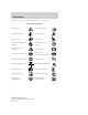
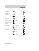
Introduction These are some of the symbols you may see on your vehicle.
Introduction Vehicle Symbol Glossary Power Windows Front/Rear Power Window Lockout Child Safety Door Lock/Unlock Interior Luggage Compartment Release Symbol Panic Alarm Engine Oil Engine Coolant Engine Coolant Temperature Do Not Open When Hot Battery Avoid Smoking, Flames, or Sparks Battery Acid Explosive Gas Fan Warning Power Steering Fluid Maintain Correct Fluid Level Emission System Engine Air Filter Passenger Compartment Air Filter Jack Check Fuel Cap Low Tire Pressure Warning MAX
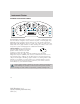
Instrument Cluster WARNING LIGHTS AND CHIMES Warning lights and gauges can alert you to a vehicle condition that may become serious enough to cause extensive repairs. A warning light may illuminate when a problem exists with one of your vehicle’s functions. Many lights will illuminate when you start your vehicle to make sure the bulbs work. If any light remains on after starting the vehicle, refer to the respective system warning light for additional information.
Instrument Cluster Check fuel cap (if equipped): Illuminates when the fuel cap may not be properly installed. Continued driving with this light on may cause the Check engine warning light to come on, refer to Fuel filler cap in the Maintenance and Specification chapter.
Instrument Cluster Safety belt: Reminds you to fasten your safety belt. A chime will also sound to remind you to fasten your safety belt. Charging system: Illuminates when the battery is not charging properly. Engine oil pressure: Illuminates when the oil pressure falls below the normal range, refer to Engine oil in the Maintenance and Specifications chapter. Engine coolant level: Illuminates when the engine coolant is low. Stop the vehicle as soon as possible, switch off the engine and let cool.
Instrument Cluster Speed control: Illuminates when the speed control is engaged. Turns off when the speed control system is disengaged. Low washer fluid (if equipped): Illuminates when the windshield washer fluid is low. Door ajar (if equipped): Illuminates when the ignition is in the ON position and any door or decklid is open. Anti-theft system: Flashes when the Securilock娂 Passive Anti-theft System has been activated.
Instrument Cluster GAUGES Speedometer: Indicates the current vehicle speed. Engine coolant temperature gauge: Indicates engine coolant temperature. At normal operating temperature, the needle will be in the normal range (between “H” and “C”). If it enters the red section, the engine is overheating. Stop the vehicle as soon as safely possible, switch off the engine and let the engine cool. Never remove the coolant reservoir cap while the engine is running or hot.
Instrument Cluster Fuel gauge: Indicates approximately how much fuel is left in the fuel tank (when the ignition is in the ON position). The fuel gauge may vary slightly when the vehicle is in motion or on a grade. The FUEL icon and arrow indicates which side of the vehicle the fuel filler door is located. Refer to Filling the tank in the Maintenance and Specifications chapter for more information. Tachometer: Indicates the engine speed in revolutions per minute.
Entertainment Systems AUDIO SYSTEMS AM/FM stereo/ single CD sound system (if equipped) 19 18 1 17 2 16 3 15 4 14 5 COMPRESS 13 12 11 10 9 8 7 6 Accessory delay: Your vehicle is equipped with accessory delay. With this feature, the window switches and radio may be used for up to ten minutes after the ignition is turned off or either front door is opened. / Tuner: Press to 1. manually go up or down the radio frequency. Also use in menu mode to select various settings. 2.
Entertainment Systems Autoset: Allows you to set the strongest local radio stations without losing your original manually set preset stations for AM/FM1/FM2 . Press / / SEEK to set. MENU to access. Use When the six strongest stations are filled, the station stored in preset 1 will begin playing. If there are less than six strong stations, the system will store the last one in the remaining presets. Bass: Press to adjust the bass setting. Use Treble: Press to adjust the treble setting. Use / / / SEEK / .
Entertainment Systems 9. Repeat: Press to repeat the current CD track. 10. Fast forward: Press to manually advance in a CD track. 11. Rewind: Press to manually reverse in a CD track. 12. Memory presets: To set a station: Select frequency band AM/FM; tune to a station, press and hold a preset button until sound returns. 13. Scan: Press for a brief sampling of radio stations or CD tracks. Press again to stop. 14. Seek: Press to access the previous strong station or track. 15.
Entertainment Systems 19. CD slot: Insert a CD label side up. Premium/Audiophile In-Dash Six CD/MP3 Sound System (if equipped) Accessory delay: Your vehicle is equipped with accessory delay. With this feature, the window switches and radio may be used for up to ten minutes after the ignition switch is turned off or until either front door is opened. / Tune/Disc selector: 1. Press to manually go up or down the radio frequency or to select a desired disc. Also use in menu mode to select various settings. 2.
Entertainment Systems 3. Menu: Press to toggle through the following modes: Autoset: Allows you to set the strongest local radio stations without losing your original manually set preset stations for AM/FM1/FM2 . Use / / SEEK to turn on/off. When the six strongest stations are filled, the station stored in preset 1 will begin playing. If there are less than six strong stations, the system will store the last one in the remaining presets. Bass: Press to adjust the bass setting.
Entertainment Systems Repeat: Available only in CD mode. Press to repeat the current CD track. RDS (Available on Audiophile radios only): Allows you to search RDS-equipped stations for a certain category of music format: Classic, Country, Info, Jazz/RB, Religious, Rock, Soft, Top 40. RDS (only available in FM mode) must be activated to access Find and Show functions. To activate, press and hold MENU until RDS (ON/OFF) appears in the display. Press MENU repeatedly to scroll through Find, Show and RDS.
Entertainment Systems 10. Fast forward: Press to manually advance in a CD track. 11. Rewind: Press to manually reverse in a CD track. 12. Memory presets: To set a station: Select frequency band AM/FM; tune to a station, press and hold a preset button until sound returns. 13. Scan: Press for a brief sampling of radio stations or CD tracks. Press again to stop. 14. Seek: Press to access the previous strong station or track. 15. AM/FM: Press to select AM/FM frequency band. 16.
Entertainment Systems 20. CD slot: Insert a CD label side up. GENERAL AUDIO INFORMATION Radio frequencies: AM and FM frequencies are established by the Federal Communications Commission (FCC) and the Canadian Radio and Telecommunications Commission (CRTC). Those frequencies are: AM: 530, 540–1700, 1710 kHz FM: 87.7, 87.9–107.7, 107.
Entertainment Systems jammed. It is recommended that homemade CDs be identified with permanent felt tip marker rather than adhesive labels. Ballpoint pens may damage CDs. Please contact your authorized dealer for further information. Audio system warranty and service Refer to the Warranty Guide for audio system warranty information. If service is necessary, see your dealer or qualified technician. Navigation system (if equipped) Your vehicle may be equipped with a Navigation System.
Entertainment Systems • REV — Press to reverse within the active CD track or DVD chapter in play mode. Also press to move the cursor left in the menu active mode. • FWD — Press to advance within the active CD track or DVD chapter in play mode. Also press to move the cursor right in the menu active mode. 2. PLAY/PAUSE control Press to playback or pause the DVD. 3. DIM control Press (+) to increase or (-) to decrease the brightness on the screen. 4.
Entertainment Systems DVD control features Menu control Press the MENU control to enter the DVD menu. This allows you to navigate and select within the DVD generated menu structure.
Entertainment Systems REV/FWD control Press the REV/FWD control during playback mode to reverse or advance at a normal speed. Press the REV/FWD control again to cancel the reverse/advance action and return to normal playback mode NEXT REV Enter control The ENTER control allows you to select highlighted items when in MENU mode. CD play mode Press NEXT during CD play to advance to the next track.
Entertainment Systems screen within the wide screen. It may be desirable to view this type of movie in zoom mode. To enter zoom mode, press DISP once for the player menu and again to adjust the display setting. Select zoom from the screen settings by using the arrow and ENTER controls. Remote control 1. REV (REVERSE) control Press to reverse the direction of the DVD movie. 2. FWD (FORWARD) control Press to advance the direction of the DVD movie. 3.
Entertainment Systems In stop mode, press the control to select the next audio memory preset. 7. MENU/MODE control In DVD playback mode, press to access the disc menu. In stop mode, press to change media types (e.g. AM, FM, CD . . . ) 8. VOL (VOLUME) control Press (+) to increase or (-) to decrease the volume level. Dual play mode Press the radio preset controls 2 and 4 at the same time to enable or disable dual play.
Entertainment Systems Battery replacement Batteries are provided with the remote control unit. Since all batteries have a limited shelf life, replace them when the remote control fails to control the DVD player. There is a LED indicator light on the remote control that will illuminate when any control is pressed. Slide the battery cover off as shown on the remote control to access the batteries. The remote control unit uses two AAA batteries.
Entertainment Systems Wireless headphones Your system is equipped with 2 sets of wireless headphones. (Two AAA batteries are needed to operate the headphones.) Batteries are included. To install the batteries, remove the screw at the bottom of the cover. Then, lightly press down on top, and slide the cover off. When replacing the batteries, use two new batteries (alkaline recommended) and install them with the correct orientation as indicated in the battery housing.
Entertainment Systems Note: The volume level of the wireless headphones can only be controlled by the thumbwheel. Neither the remote control nor the rear seat controls will affect the volume output of the wireless headphones. When not using the headphones, turn them off to preserve battery life. The headphones will automatically turn off after five minutes if they have not received an infrared audio signal from the Family Entertainment System (FES).
Entertainment Systems 3. Dimmer switch. Press +/- to increase/decrease the brightness of the display. Playback and format • The DVD player of your Family Entertainment DVD System can only be used in the “playback” mode. (The DVD player does not offer a record feature.) • The system plays standard CDs, DVDs and also plays most CD R/W, DVD R/W, VCD and MP3 media. Saving MP3 files • Your Family Entertainment System supports discs containing up to 255 files. Discs containing more than 255 files will not play.
Entertainment Systems • If the Family Entertainment System (FES) is playing and the ignition is turned OFF, the system will turn off, and suspend playback. When the ignition is turned on again, playback will begin from the last selected media source when the play control is pressed. • To disable the DVD player rear controls, simultaneously press the 3 and 5 memory presets on the radio face. To enable the DVD player rear controls again, press the 3 and 5 presets simultaneously.
Entertainment Systems 2. Connect the left and right audio lines to the WHITE (left) and RED (right) auxiliary input jacks respectively. 3. Press the MODE control repeatedly until DVD/CD AUX (no disc in player) or DVD/CD play (disc in player) illuminates in the radio display. If a disc is in the system, playback should begin. To enable the aux inputs, press the STOP control or press the AUX control on the DVD player.
Entertainment Systems Safety information Read all the safety and operating instructions before operating the system and retain for future reference. • Do not attempt to service, repair or modify the Family Entertainment DVD System. See your Ford or Lincoln Mercury dealer. • Do not insert foreign objects into the DVD compartment. The front glass on the flip-down liquid crystal display (LCD) may break when hit with a hard surface. If the glass breaks, do not touch the liquid crystalline material.
Entertainment Systems residential installation. This equipment generates, uses and can radiate radio frequency energy. If not installed and used in accordance with the instructions, the Family Entertainment System (FES) may cause harmful interference with radio communications. However, there is no guarantee that interference will not occur in a particular installation.
Entertainment Systems Foreign substances Exercise care to prevent dirt and foreign objects from entering the DVD player compartment. If liquid is accidentally spilled onto the system, immediately turn the system OFF and consult a qualified service technician. Cleaning compact discs Inspect all discs for contamination before playing. If necessary, clean discs only with an approved CD cleaner and wipe from the center out to the edge. Do not wipe in a circular motion.
Climate Controls DUAL ZONE AUTOMATIC TEMPERATURE CONTROL (IF EQUIPPED) Defrost: Distributes outside air through the windshield defroster 1. and demister vents. Can be used to clear thin ice or fog from the windshield. To exit select another mode. 2. Passenger temperature control: Press to increase/decrease the airflow temperature for the passenger in the front of the vehicle. 3. R Rear defroster: Press to activate/deactivate rear window defroster.
Climate Controls 8. 9. : Distributes air through the instrument panel and floor vents. : Distributes air through the instrument panel vents. 10. Manual override controls: Allows you to manually select where airflow is directed. To return to full automatic control, press AUTO. Front fan speed control: Press to manually increase or 11. decrease the fan speed. To return to automatic fan operation, press AUTO. 12. EXT: Press to display outside temperature. Press again to display cabin temperature settings.
Climate Controls Dual Zone Automatic Temperature Control with heated seats (if equipped) Defrost: Distributes outside air through the windshield defroster 1. and demister vents. Can be used to clear thin ice or fog from the select another mode. windshield. To exit 2. Passenger temperature control: Press to increase/decrease the airflow temperature for the passenger in the front of the vehicle. Rear defroster: Press to activate/deactivate rear window 3. R defroster.
Climate Controls 7. A/C: Press to activate/deactivate air conditioning. Use with recirculated air to improve cooling performance and efficiency. Engages automatically in AUTO, defrost and floor/defrost. 8. Airflow direction control: Press to toggle through the air distribution modes listed below. The selected mode will be shown in the display. : Distributes air through the instrument panel and center console vents (if equipped).
Climate Controls Operating tips • To reduce fog build up on the windshield during humid weather, place position. the air flow selector in the • To reduce humidity build up inside the vehicle: do not drive with the airflow selector in the OFF or with recirculated air engaged. • Do not put objects under the front seats that will interfere with the airflow to the back seats. • Remove any snow, ice or leaves from the air intake area at the base of the windshield.
Climate Controls REAR WINDOW DEFROSTER R The rear defroster control is located on the climate control panel and works to clear the rear window of fog and thin ice. The ignition must be in the 3 (RUN) position to operate the rear window defroster. The rear defroster turns off automatically after 10 minutes or when the ignition is turned to the 1 (LOCK) position. To manually turn off the defroster before 10 minutes have passed, push the control again.
Lights HEADLAMP CONTROL Turns the lamps off. Turns on the parking lamps, instrument panel lamps, license plate lamps and tail lamps. P Turns the headlamps on. Autolamp control (if equipped) The autolamp system provides light sensitive automatic on-off control of the exterior lights normally controlled by the headlamp control. • To turn autolamps on, rotate the . control counterclockwise to • To turn autolamps off, rotate the .
Lights 5. Wait the desired amount of time for the exit delay you want (up to . The headlamps three minutes), then turn the headlamp switch to will turn off. High beams Pull the lever towards you, to the second detent, to activate. Pull the lever towards you again to deactivate. Flash to pass Pull toward you, to the first detent, to activate and release to deactivate.
Lights Daytime running lamps (DRL) (if equipped) Turns the headlamps on with a reduced output. To activate: • the ignition must be in the ON position, • the headlamp control is in the OFF, autolamps or parking lamp position and • the transmission must be out of the Park position. Always remember to turn on your headlamps at dusk or during inclement weather. The Daytime Running Lamp (DRL) system does not activate the tail lamps and generally may not provide adequate lighting during these conditions.
Lights • (1) 8 feet (2.4 meters) • (2) Center height of lamp to ground • (3) 25 feet (7.6 meters) • (4) Horizontal reference line 2. Measure the height of the headlamp bulb center from the ground and mark an 8 foot (2.5 meter) horizontal reference line on the vertical wall or screen at this height (a piece of masking tape works well). 3. Turn on the low beam headlamps to illuminate the wall or screen and open the hood.
Lights TURN SIGNAL CONTROL • Push down to activate the left turn signal. • Push up to activate the right turn signal. INTERIOR LAMPS Dome lamps and map lamps The map lamps are located on the overhead console. Press the controls on either side of each map lamp to turn on the lamps. Your vehicle may also have reading lamps within the rear dome lamp(s). Press the switches on either side of the dome lamp to turn on the lamps.
Lights Using the right bulbs Replacement bulbs are specified in the chart below. Headlamp bulbs must be marked with an authorized “D.O.T.” for North America and an “E” for Europe to ensure lamp performance, light brightness and pattern and safe visibility. The correct bulbs will not damage the lamp assembly or void the lamp assembly warranty and will provide quality bulb burn time.
Lights Replacing HID headlamp bulbs The low beam headlamps on your vehicle use a “high intensity discharge” source. These lamps operate at a high voltage. The bulb is NOT replaceable. When the bulb is burned out, the bulb assembly must be replaced by your authorized dealer. Replacing front parking lamp/turn signal bulbs 1. Make sure headlamp switch is in the OFF position, then open the hood. 2. Turn the front wheels inboard and loosen the three screws on the splash shield in front of the tire. 3.
Lights Replacing turn signal lamp/backup lamp bulbs The backup lamp and turn signal lamp bulbs are located in the tail lamp assembly. Follow the same steps to replace either bulb. 1. Turn signal lamp 2. Backup lamp 1. Make sure the headlamp switch is in the OFF position and open the trunk. 2. Remove the cargo net fastener. Carefully pull the carpet away to expose the backside of the tail lamp assembly. 3. Remove the nut and washer assemblies, then pull the lamp assembly away from the vehicle. 4.
Lights Replacing license plate lamp bulbs 1. Make sure the headlamp switch is in the OFF position, then remove the two screws and the license plate lamp assembly. 2. Remove bulb socket by turning counterclockwise. 3. Carefully pull the bulb out from the socket. Install new bulb(s) in reverse order. Replacing foglamp bulbs 1. Make sure the foglamp switch is in the OFF position. 2. Remove the bulb socket from the foglamp by turning counterclockwise. 3. Disconnect the electrical connector.
Driver Controls MULTI-FUNCTION LEVER Windshield wiper: For intermittent operation, move control up one position. Adjust the rotary control to the desired speed setting. Mist function: To activate mist, push control down from the OFF position and release to get one wipe. For normal or low speed wiper operation, move control up two positions from OFF. For high speed wiper operation, move control up three positions from OFF.
Driver Controls TILT STEERING WHEEL To adjust the steering wheel: 1. Pull down and hold the steering wheel release control. 2. Move the steering wheel up or down until you find the desired location. 3. Pull the steering wheel release control up. This will lock the steering wheel in position. Never adjust the steering wheel when the vehicle is moving. ILLUMINATED VISOR MIRROR Lift the mirror cover to turn on the visor mirror lamp.
Driver Controls Storage compartment Press the latch to open the storage compartment. The door will open slightly and can be moved to full open. The storage compartment may be used to secure sunglasses or a similar object. CLOCK (IF EQUIPPED) Press and release the button to adjust forward. Press and hold to fast forward. INSTRUMENT PANEL STORAGE COMPARTMENT The storage compartment may be used to secure sunglasses or similar sized objects. Press the control to open the storage compartment.
Driver Controls • Rear vent (if equipped) Use only soft cups in the cupholder. Hard objects can injure you in a collision. AUXILIARY POWER POINT (12VDC) Power outlets are designed for accessory plugs only. Do not insert any other object in the power outlet as this will damage the outlet and blow the fuse. Do not hang any type of accessory or accessory bracket from the plug. Improper use of the power outlet can cause damage not covered by your warranty.
Driver Controls When closing the power windows, you should verify they are free of obstructions and ensure that children and/or pets are not in the proximity of the window openings. Press and pull the window switches to open and close windows. • Push down (to the first detent) and hold the switch to open. • Pull up (to the first detent) and hold the switch to close. AUTO One touch up or down This feature is present on the driver’s window only.
Driver Controls Window lock The window lock feature allows only the driver to operate the power windows. To lock out all the window controls except for the driver’s press the right side of the control. Press the left side to restore the window controls. Bounce-Back (Driver’s window only) When an obstacle has been detected in the window opening as the window is moving upward, the window will automatically reverse direction and move down. This is known as “bounce-back”.
Driver Controls (darkened) state when bright lights (glare) reach the mirror. When the mirror detects bright light from behind the vehicle, it will automatically adjust (darken) to minimize glare. The mirror will automatically return to the normal state whenever the vehicle is placed in R (Reverse) to ensure a bright clear view when backing up. Do not block the sensor on the backside of the inside rear view mirror since this may impair proper mirror performance.
Driver Controls Heated outside mirrors (if equipped) Both mirrors are heated automatically to remove ice, mist and fog when the rear window defrost is activated. Do not remove ice from the mirrors with a scraper or attempt to readjust the mirror glass if it is frozen in place. These actions could cause damage to the glass and mirrors.
Driver Controls Do not use the speed control in heavy traffic or on roads that are winding, slippery or unpaved. Setting speed control The controls for using your speed control are located on the steering wheel for your convenience. 1. Press the ON control and release it. 2. Accelerate to the desired speed. OFF ON CNCL RSM SET SET 3. Press the SET + control and release it. 4. Take your foot off the accelerator pedal. light on the 5. The indicator instrument cluster will turn on.
Driver Controls Resuming a set speed Press the RES control and release it. This will automatically return the vehicle to the previously set speed. The RES control will not work if the vehicle speed is not faster than 30 mph (48 km/h). OFF ON CNCL RSM SET SET Increasing speed while using speed control There are two ways to set a higher speed: • Press and hold the SET + control until you get to the desired speed, then release the control.
Driver Controls • Depress the brake pedal or press CNCL (Cancel) until the desired vehicle speed is reached, press the SET + control. ON OFF CNCL RSM SET SET Turning off speed control There are two ways to turn off the speed control: • Depress the brake pedal or press CNCL (Cancel). This will not erase your vehicle’s previously set speed. • Press the speed control OFF control. Note: When you turn off the speed control or the ignition, your speed control set speed memory is erased.
Driver Controls In Radio mode: • Press SEEK to access the next/previous strong station. In CD mode: • Press SEEK to listen to the next track on the disc. VOL SEEK MEDIA MUTE In any mode: • Press VOL up or down to adjust the volume. • Press MUTE to mute the volume. MOON ROOF (IF EQUIPPED) You can move the glass panel of the moon roof back to open or tilt up to ventilate the vehicle. Do not let children play with the moon roof or leave children unattended in the vehicle.
Driver Controls When closing the moon roof, you should verify that it is free of obstructions and ensure that children and/or pets are not in the proximity of the moon roof opening. To close the moon roof: To close, press and release the front portion of the control. To vent: To tilt the moon roof into the vent position (when the glass panel is closed), press and hold the middle portion of the control.
Driver Controls Retain the original transmitter for use in other vehicles as well as for future programming procedures (i.e. new HomeLink威 equipped vehicle purchase). It is also suggested that upon the sale of the vehicle, the programmed Homelink威 buttons be erased for security purposes, refer to Programming in this section. Programming Do not program HomeLink威 with the vehicle parked in the garage.
Driver Controls 5. Press and hold the just-trained HomeLink威 button and observe the indicator light. If the light is constant, programming is complete and your device should activate when the HomeLink威 button is pressed and released. Note: To program the remaining two HomeLink威 buttons, begin with Step 2 in the “Programming” section — do not repeat Step 1.
Driver Controls seconds (“cycle”) your hand-held transmitter until the frequency signal has been accepted by the HomeLink威. The indicator light will flash slowly and then rapidly after HomeLink威 accepts the radio frequency signal. • Proceed with Step 4 in the “Programming” section. Operating the HomeLink姞 Wireless Control System To operate, simply press and release the appropriate HomeLink威 button.
Driver Controls For questions or comments, contact HomeLink威 at www.homelink.com or 1–800–355–3515. MESSAGE CENTER With the ignition in the ON position, the message center, located on your instrument cluster, displays important vehicle information through a constant monitor of vehicle systems. You may select display features on the message center for a display of status. The system will also notify you of potential vehicle problems with a display of system warnings followed by a long indicator chime.
Driver Controls Distance to empty (DTE) Selecting this function from the INFO menu estimates approximately how far you can drive with the fuel remaining in your tank under normal driving conditions. Remember to turn the ignition OFF when refueling to allow this feature to correctly detect the added fuel. The DTE function will display LOW FUEL LEVEL when you have approximately 50 miles (80 km) to empty. If you RESET this warning message, this display and tone will return within 10 minutes.
Driver Controls Fuel Used Selecting this function from the INFO menu, XX.X G USED will display the fuel used since last reset. The information displayed will be in gallons or liters, depending on English/metric mode state. Press and hold RESET to reset mode. Trip elapsed drive time Select this function from the INFO menu to display a timer. To operate the Trip Elapsed Drive Time perform the following: 1. Press and release RESET in order to start the timer. 2. Press and release RESET to pause the timer. 3.
Driver Controls 1. Turn ignition to the ON position. 2. Start the engine. 3. Press the INFO button repeatedly until the Compass and Odometer are displayed. (Do not select Trip, DTE, or AFE. The top of the message center must be blank). Note: If message center displays the message ⬙SLOW CIRCLES TO CALIBRATE⬙, then perform the CALIBRATION PROCEDURE. 4. Determine your magnetic zone by referring to the zone map. 3 2 1 15 4 14 13 5 12 6 7 8 9 1011 5.
Driver Controls 2. Start the engine. 3. Press the INFO button repeatedly until the Compass and Odometer are displayed. (Do not select Trip, DTE, or AFE. The top of the message center must be blank). Note: If message center displays the message ⬙SLOW CIRCLES TO CALIBRATE⬙, then continue with Step 4. Otherwise, if a heading is displayed, continue with Step 5. 4.
Driver Controls 2. Pressing the RESET control cycles the message center through each of the language choices. 3. Press and hold the RESET control to set the language choice. Units (English/Metric) 1. Select this function from the SETUP menu for the current units to be displayed. 2. Press the RESET control to change from English to Metric. System check Selecting this function from the SETUP menu causes the message center to cycle through each of the systems being monitored.
Driver Controls System warnings System warnings alert you to possible problems or malfunctions in your vehicle’s operating systems. In the event of a multiple warning situation, the message center will cycle the display to show all warnings by displaying each one for several seconds. The message center will display the last selected feature if there are no more warning messages.
Driver Controls PASSENGER DOOR AJAR. Displayed when the passenger side door is not completely closed. LEFT REAR DOOR AJAR. Displayed when the left rear door is not completely closed. RIGHT REAR DOOR AJAR. Displayed when the right rear door is not completely closed. PARK BRAKE ENGAGED. Displayed when the park brake is engaged. If the warning stays on after the park brake is off, contact your authorized dealer as soon as possible. LOW FUEL LEVEL. Displayed as an early reminder of a low fuel condition.
Driver Controls To reset the oil monitoring system to 100% after each oil change [approximately 5,000 miles (8,000 km) or 180 days] perform the following: To reset the oil life to 100% with system warnings CHANGE OIL SOON/OIL CHANGE REQUIRED displayed: 1. Select this function from the SETUP control for current display mode. 2. Press and release the RESET control to display “IF NEW OIL HOLD RESET”. 3. Press and hold the RESET control to display OIL LIFE SET TO 100%. Your oil life is now reset.
Driver Controls 3. Press and hold RESET control again until OIL LIFE SET TO 100% is displayed. Your oil life is now reset. INTERIOR TRUNK CONTROL Press the remote trunk release control on the instrument panel to the left of the steering wheel. CARGO AREA FEATURES Cargo net (if equipped) The cargo net secures lightweight objects in the cargo area. Attach the net to the anchors provided. Do not put more than 50 lbs. (22 kg) in the net. This net is not designed to restrain objects during a collision.
Locks and Security KEYS One key operates all the locks and starts the vehicle. Always carry a spare key with you in case of an emergency. Your keys are programmed to your vehicle; using a non-programmed key will not permit your vehicle to start. If you lose your authorized dealer supplied keys, replacement keys are available through your authorized dealer. Refer to the SecuriLock娂 passive anti-theft system section later in this chapter for more information.
Locks and Security 1. Place the key in the ignition and turn the ignition to the 3 (RUN) position. 2. Press the power door unlock control on the door panel three times. 3. Turn the ignition from the 3 (RUN) position to the 1 (LOCK) position. 4. Press the power door unlock control on the door panel three times. 5. Turn the ignition back to the 3 (RUN) position. The horn will chirp one time to confirm programming mode has been entered and is active. 6.
Locks and Security INTERIOR LUGGAGE COMPARTMENT RELEASE Your vehicle is equipped with a mechanical interior luggage compartment release handle that provides a means of escape for children and adults in the event they become locked inside the luggage compartment. Adults are advised to familiarize themselves with the operation and location of the release handle. To open the luggage compartment door (lid) from within the luggage compartment, pull the illuminated “T” shaped handle and push up on the trunk lid.
Locks and Security REMOTE ENTRY SYSTEM This device complies with part 15 of the FCC rules and with RS-210 of Industry Canada. Operation is subject to the following two conditions: (1) This device may not cause harmful interference, and (2) This device must accept any interference received, including interference that may cause undesired operation. Changes or modifications not expressly approved by the party responsible for compliance could void the user’s authority to operate the equipment.
Locks and Security 2. Press and release again within three seconds to unlock all the doors. The remote entry system activates the illuminated entry feature; this feature turns on the lamps for 25 seconds or until the ignition is turned to the 3 (RUN) position. The inside lights will not turn off if: • they have been turned on using the dimmer control or • any door is open. The battery saver feature will turn off the interior lamps 30 minutes after the ignition is turned to the 1 (LOCK) position.
Locks and Security Press to automatically move the seat, mirrors and adjustable pedals to the desired memory position (the positions correspond to the transmitter being used). Note: You can associate a specific remote entry transmitter to each memory position. For more information on programming the transmitters to Driver 1 and Driver 2 memory positions respectively, refer to How to reprogram your remote entry transmitters later in this chapter.
Locks and Security 2. Do not wipe off any grease on the battery terminals on the back surface of the circuit board. 3. Remove the old battery. Note: Please refer to local regulations when disposing of transmitter batteries. 4. Insert the new battery. Refer to the diagram inside the remote entry transmitter for the correct orientation of the battery. Press the battery down to ensure that the battery is fully seated in the battery housing cavity. 5. Snap the two halves back together.
Locks and Security To reprogram the remote entry transmitters: 1. Ensure the vehicle is electronically unlocked. 2. Put the key in the ignition. 3. Cycle eight times rapidly (within 10 seconds) between the 1 (LOCK) position and 3 (RUN). Note: The eighth turn must end in the 3 (RUN) position. 4. The doors will lock, then unlock, to confirm that the programming mode has been activated. 5. Within 20 seconds press any button on the remote entry transmitter to be programmed.
Locks and Security The inside lights will not turn off if: • they have been turned on with the dimmer control, or • any door is open. Battery saver The battery saver will shut off the interior lamps 30 minutes after the ignition has been turned to the 1 (LOCK) position. • If the dome lamps were turned on using the panel dimmer control, the battery saver will shut off them off 30 minutes after the ignition has been turned to the 1 (LOCK) position.
Locks and Security KEYLESS ENTRY SYSTEM You can use the keyless entry keypad to: • lock or unlock the doors without using a key. • open the trunk. • recall memory seat/power mirrors/adjustable pedals positions 1 or 2. The keypad can be operated with the factory set 5–digit entry code; this code is located on the owner’s wallet card in the glove box, is marked on the computer module, and is available from your authorized dealer. You can also create your own 5–digit personal entry code.
Locks and Security Tips: • Do not set a code that uses five of the same number. • Do not use five numbers in sequential order. • The factory set code will work even if you have set your own personal code. Erasing personal code 1. Enter the factory set 5–digit code. 2. Within five seconds, press the 1 • 2 on the keypad and release. 3. Press and hold the 1 • 2 for two seconds. This must be done within five seconds of completing Step 2.
Locks and Security • the ignition is in the 3 (RUN) position, • you shift into any gear putting the vehicle in motion, and • the brake pedal is released and the vehicle attains a speed greater than 5 mph (8 km/h). The autolock feature repeats when: • any door is opened then closed while the ignition is in the 3 (RUN) position, and • you put the vehicle in motion by releasing the brake pedal and the vehicle attains a speed greater than 5 mph (8 km/h).
Locks and Security 3. Enter factory–set 5–digit entry code. 4. Press and hold the 7 • 8. While holding the 7 • 8 press the 3 • 4. 5. Release the 3 • 4. 6. Release the 7 • 8. The user should receive a horn chirp to indicate the system has been disabled or a chirp followed by a honk to indicate the system has been enabled. SECURILOCK姟 PASSIVE ANTI-THEFT SYSTEM SecuriLock娂 passive anti-theft system is an engine immobilization system.
Locks and Security If a problem occurs with the SecuriLock娂 system, the indicator will flash rapidly or glow steadily when the ignition is in the 3 (RUN) position. If this occurs, the vehicle will not start and should be taken to an authorized dealer for service. Automatic arming The vehicle is armed immediately after switching the ignition to the 1 (LOCK) position. The theft indicator will flash every two seconds to act as a theft deterrent when the vehicle is armed.
Locks and Security • If two previously programmed coded keys are not available, you must take your vehicle to your authorized dealer to have the spare key(s) programmed. Please read and understand the entire procedure before you begin. 1. Insert the first previously programmed coded key into the ignition. 2. Turn the ignition from the 1 (LOCK) position to the 3 (RUN) position. Keep the ignition in the 3 (RUN) position for at least three seconds, but no more than 10 seconds. 3.
Locks and Security PERIMETER ALARM SYSTEM (IF EQUIPPED) The perimeter anti-theft system will help prevent your vehicle from unauthorized entry. If there is any potential perimeter anti-theft problem with your vehicle, ensure ALL remote entry transmitters are brought to the authorized dealer to aid in troubleshooting. Arming the system When armed, this system will respond if unauthorized entry is attempted. When unauthorized entry occurs, the system will flash the turn signal lamps and will sound the horn.
Locks and Security • Press the 7 • 8 and 9 • 0 controls on the keyless entry pad at the same time to lock the doors (driver’s door must be closed). There is a 20 second countdown when any of the above actions occur before the vehicle becomes armed. Each door, the hood or the trunk is armed individually, and if any are open, they must be closed for the system to enter the 20 second countdown.
Seating and Safety Restraints SEATING Notes: Reclining the seatback can cause an occupant to slide under the seat’s safety belt, resulting in severe personal injuries in the event of a collision. Do not pile cargo higher than the seatbacks to reduce the risk of injury in a collision or sudden stop. Before returning the seatback to its original position, make sure that cargo or any objects are not trapped behind the seatback.
Seating and Safety Restraints Push release button to lower head restraint. Using the manual lumbar support (if equipped) The lumbar support control is located on the outboard side of the seatback. Move the control up or down to adjust lumbar support. Folding down the front passenger seatback The front passenger seatback can be folded to a horizontal position to make room for a long load. To fold the seatback: 1. Move the seat as far back as possible. 2.
Seating and Safety Restraints Cover sharp edges on the load to help prevent injury to occupants. Secure the load to help prevent shifting during sudden stops. Before returning the seatback to its original position, make sure that cargo or any objects are not trapped behind the seatback. After returning the seatback to its original position, pull on the seatback to ensure that it has fully latched. An unlatched seat may become dangerous in the event of a sudden stop or collision.
Seating and Safety Restraints Pull lever up to adjust seatback. Before returning the seatback to its original position, make sure that cargo or any objects are not trapped behind the seatback. After returning the seatback to its original position, pull on the seatback to ensure that it has fully latched. An unlatched seat may become dangerous in the event of a sudden stop or collision. Adjusting the front power seat (if equipped) Never adjust the driver’s seat or seatback when the vehicle is moving.
Seating and Safety Restraints To reduce the risk of possible serious injury: Do not hang objects off seat back or stow objects in map pocket (if equipped) when a child is in the front passenger seat. Do not place objects underneath the front passenger seat or between the seat and the center console (if equipped). Check the “passenger airbag off” or “pass airbag off” indicator lamp for proper airbag status. Refer to Front passenger sensing system section for additional details.
Seating and Safety Restraints Press the control (if equipped) to recline the seatback forward or rearward. Heated seats (if equipped) To operate the heated seats: • Push the control located on the climate control system panel once to activate high heat. • Push twice to activate low heat. • Push a third time to deactivate. The indicator light on the control will illuminate when activated. For low heat, one light will be lit; for high heat, both lights will be lit.
Seating and Safety Restraints A position can be recalled: • in any gearshift position if the ignition is not in the RUN position. • only in P (Park) or N (Neutral) if the ignition is in the RUN position. A memory seat position may be programmed at any time. The memory positions are also recalled when you press your remote entry transmitter UNLOCK control (if the transmitter is programmed to a memory position) or, when you enter a valid personal entry code that is programmed to a memory position.
Seating and Safety Restraints To lower the seatback(s) from inside the vehicle, pull the strap located on the outboard side of the seatback to release it, and then fold seatback down. When raising the seatback(s), make sure you hear the seat latch into place. Before returning the seatback to its original position, make sure that cargo or any objects are not trapped behind the seatback. After returning the seatback to its original position, pull on the seatback to ensure that it has fully latched.
Seating and Safety Restraints SAFETY RESTRAINTS Personal Safety System姟 The Personal Safety System娂 provides an improved overall level of frontal crash protection to front seat occupants and is designed to help further reduce the risk of airbag-related injuries. The system is able to analyze different occupant conditions and crash severity before activating the appropriate safety devices to help better protect a range of occupants in a variety of frontal crash situations.
Seating and Safety Restraints Driver and passenger dual-stage airbag supplemental restraints The dual-stage airbags offer the capability to tailor the level of airbag inflation energy. A lower, less forceful energy level is provided for more common, moderate-severity impacts. A higher energy level is used for the most severe impacts. Refer to Airbag supplemental restraints section in this chapter.
Seating and Safety Restraints (child size) occupants from airbag deployments when they are improperly seated or restrained in the front passenger seat contrary to proper child-seating or restraint usage recommendations. Even with this technology, parents are STRONGLY encouraged to always properly restrain children in the rear seat.
Seating and Safety Restraints position sensor, and passenger occupant classification sensor. In addition, the RCM also monitors the restraints warning light in the instrument cluster. A difficulty with the system is indicated by one or more of the following. • The warning light will either flash or stay lit. • The warning light will not illuminate immediately after ignition is turned on. • A series of five beeps will be heard.
Seating and Safety Restraints In a rollover crash, an unbelted person is significantly more likely to die than a person wearing a seat belt. Each seating position in your vehicle has a specific safety belt assembly which is made up of one buckle and one tongue that are designed to be used as a pair. 1) Use the shoulder belt on the outside shoulder only. Never wear the shoulder belt under the arm. 2) Never swing the safety belt around your neck over the inside shoulder.
Seating and Safety Restraints if your vehicle receives an impact of 5 mph (8 km/h) or more, the safety belt will become locked and help reduce your forward movement. Energy Management Feature — Front Outboard • This vehicle has a safety belt system with an energy management feature at the front seats to help further reduce the risk of injury in the event of a head-on collision. • This safety belt system has a retractor assembly that is designed to extend the safety belt webbing in a controlled manner.
Seating and Safety Restraints How to use the automatic locking mode • Buckle the combination lap and shoulder belt. • Grasp the shoulder portion and pull downward until the entire belt is pulled out. • Allow the belt to retract. As the belt retracts, you will hear a clicking sound. This indicates the safety belt is now in the automatic locking mode.
Seating and Safety Restraints Safety belt height adjustment Your vehicle has safety belt height adjustments for the front outboard seating positions. Adjust the height of the shoulder belt so the belt rests across the middle of your shoulder. To adjust the shoulder belt height, squeeze the button and slide the height adjuster up or down. Release the button and pull down on the height adjuster to make sure it is locked in place.
Seating and Safety Restraints BeltMinder姞 The BeltMinder威 feature is a supplemental warning to the safety belt warning function. This feature provides additional reminders by intermittently sounding a chime and illuminating the safety belt warning light in the instrument cluster when the driver’s and front passenger’s safety belt is unbuckled.
Seating and Safety Restraints If... The driver’s or front passenger’s safety belt becomes unbuckled for approximately 1 minute while the vehicle is traveling at least 3 mph (5 km/h) and more than 1-2 minutes have elapsed since the ignition switch has been turned to ON... Then... The BeltMinder威 feature is activated the safety belt warning light illuminates and the warning chime sounds for 6 seconds every 30 seconds, repeating for approximately 5 minutes or until the safety belts are buckled.
Seating and Safety Restraints Reasons given... “Traffic is light” “Belts wrinkle my clothes” “The people I’m with don’t wear belts” “I have an airbag” “I’d rather be thrown clear” Consider... Nearly 1 of 2 deaths occur in single-vehicle crashes, many when no other vehicles are around. Possibly, but a serious crash can do much more than wrinkle your clothes, particularly if you are unbelted. Set the example, teen deaths occur 4 times more often in vehicles with TWO or MORE people.
Seating and Safety Restraints Read Steps 1 - 4 thoroughly before proceeding with the deactivation/activation programming procedure. Note: The driver and front passenger BeltMinder威 features must be disabled/enabled separately. Both cannot be disable/enabled during the same key cycle.
Seating and Safety Restraints Safety belt extension assembly If the safety belt is too short when fully extended, there is a 8 inch (20 cm) safety belt extension assembly that can be added (part number 611C22). This assembly can be obtained from an authorized dealer. Use only extensions manufactured by the same supplier as the safety belt. Manufacturer identification is located at the end of the webbing on the label.
Seating and Safety Restraints AIRBAG SUPPLEMENTAL RESTRAINT SYSTEM (SRS) The airbag supplemental restraint system (SRS) is designed to work in conjunction with the safety belts to help protect the driver and front outboard passenger from certain upper body injuries. The term “supplemental restraint” means the airbags are intended as a supplement to the safety belts.
Seating and Safety Restraints All occupants of the vehicle, including the driver, should always properly wear their safety belts, even when an air bag supplemental restraint system (SRS) is provided. Always transport children 12 years old and under in the back seat and always properly use appropriate child restraints. National Highway Traffic Safety Administration (NHTSA) recommends a minimum distance of at least 10 inches (25 cm) between an occupant’s chest and the driver airbag module.
Seating and Safety Restraints Children and airbags Children must always be properly restrained. Accident statistics suggest that children are safer when properly restrained in the rear seating positions than in the front seating position. Failure to follow these instructions may increase the risk of injury in a collision. Airbags can kill or injure a child in a child seat. NEVER place a rear-facing child seat in front of an active airbag.
Seating and Safety Restraints The airbags inflate and deflate rapidly upon activation. After airbag deployment, it is normal to notice a smoke-like, powdery residue or smell the burnt propellant. This may consist of cornstarch, talcum powder (to lubricate the bag) or sodium compounds (e.g., baking soda) that result from the combustion process that inflates the airbag. Small amounts of sodium hydroxide may be present which may irritate the skin and eyes, but none of the residue is toxic.
Seating and Safety Restraints • diagnostic module. • and the electrical wiring which connects the components. The diagnostic module monitors its own internal circuits and the supplemental airbag electrical system wiring (including the impact sensors), the system wiring, the airbag system readiness light, the airbag back up power and the airbag ignitors.
Seating and Safety Restraints that the front passenger frontal airbag is disabled. The indicator lamp is located above the glove box on the instrument panel. Note: The indicator lamp will illuminate for a short period of time when the ignition is turned to the ON position to confirm it is functional. When the front passenger seat is not occupied (empty seat) or in the event that the front passenger frontal airbag is enabled (may inflate), the indicator lamp will be unlit.
Seating and Safety Restraints Occupant Pass Airbag Off Indicator Light Unlit Lit Empty seat Small child in child safety seat or booster Small child with safety Lit belt buckled or unbuckled Adult Unlit Passenger Airbag Disabled Disabled Disabled Enabled Even with Advanced Restraints Systems, children 12 and under should be properly restrained in the back seat. After all occupants have adjusted their seats and put on safety belts, it’s very important that they continue to sit properly.
Seating and Safety Restraints Objects Pass Airbag Off Indicator Light Unlit Passenger Airbag Small (i.e. 3 ring Disabled binder, small purse, bottled water) Medium (i.e.
Seating and Safety Restraints In case there is a problem with the front passenger sensing system, the airbag readiness lamp in the instrument cluster will stay lit. If the airbag readiness lamp is lit, do the following: The driver and/or adult passengers should check for any objects that may be lodged underneath the front passenger seat or cargo interfering with the seat.
Seating and Safety Restraints A difficulty with the system is indicated by one or more of the following: • The readiness light (same light for front and side airbag system) will either flash or stay lit. • The readiness light will not illuminate immediately after ignition is turned on. • A series of five beeps will be heard. The tone pattern will repeat periodically until the problem and/or light are repaired.
Seating and Safety Restraints automotive safety experts known as the Side Airbag Technical Working Group. These recommended testing procedures help reduce the risk of injuries related to the deployment of side airbags. The side airbag system consists of the following: • An inflatable nylon bag (airbag) with a gas generator concealed behind the outboard bolster of the driver and front passenger seatbacks. • A special seat cover designed to allow airbag deployment.
Seating and Safety Restraints Several air bag system components get hot after inflation. Do not touch them after inflation. If the side airbag has deployed, the airbag will not function again. The side airbag system (including the seat) must be inspected and serviced by an authorized dealer. If the airbag is not replaced, the unrepaired area will increase the risk of injury in a collision.
Seating and Safety Restraints All occupants of the vehicle including the driver should always wear their safety belts even when an airbag SRS and Safety Canopy娂 system is provided. To reduce risk of injury, do not obstruct or place objects in the deployment path of the inflatable Safety Canopy娂.
Seating and Safety Restraints The Safety Canopy娂 system, in combination with safety belts, can help reduce the risk of severe injuries in the event of a significant side impact collision or rollover event. Children 12 years old and under should always be properly restrained in the second row seats.
Seating and Safety Restraints If the Safety Canopy娂 system has deployed, the Safety Canopy娂 will not function again unless replaced. The Safety Canopy娂 system (including the A, B, and C pillar trim) must be inspected and serviced by an authorized dealer. If the Safety Canopy娂 is not replaced, the unrepaired area will increase the risk of injury in a collision. Determining if the system is operational The SRS uses a readiness light in the instrument cluster or a tone to indicate the condition of the system.
Seating and Safety Restraints must put them in safety seats made especially for children. Many states require that children use approved booster seats until they are eight years old. Check your local and state or provincial laws for specific requirements regarding the safety of children in your vehicle. When possible, always place children under age 12 in the rear seat of your vehicle.
Seating and Safety Restraints bend comfortably. Booster seats may also make the shoulder belt fit better and more comfortably. Try to keep the belt near the middle of the shoulder. When children should use booster seats Children need to use booster seats from the time they outgrow the toddler seat until they are big enough for the vehicle seat and lap/shoulder belt to fit properly. Generally this is when they weigh about 80 lb. (36 kg) (about 8 to 12 years old).
Seating and Safety Restraints • Those with a high back. If, with a backless booster seat, you cannot find a seating position that adequately supports your child’s head, a high back booster seat would be a better choice. Either type can be used at any seating position equipped with lap/shoulder belts if your child is over 40 lb. (18 kg). Children and booster seats vary widely in size and shape.
Seating and Safety Restraints Move a child to a different seating location if the shoulder belt does not stay positioned on the shoulder during use. Follow all instructions provided by the manufacturer of the booster seat. Never put the shoulder belt under a child’s arm or behind the back because it eliminates the protection for the upper part of the body and may increase the risk of injury or death in a collision. Never use pillows, books, or towels to boost a child.
Seating and Safety Restraints • Place seat back in upright position. • Put the safety belt in the automatic locking mode. Refer to Automatic locking mode. • LATCH lower anchors are recommended for use by children up to 48 lb (22 kg) in a child restraint. Top tether anchors can be used for children up to 60 lb (27 kg) in a child restraint, and to provide upper torso restraint for children up to 80 lb (36 kg) using an upper torso harness and a belt-positioning booster.
Seating and Safety Restraints 1. Position the child safety seat in a seat with a combination lap and shoulder belt. 2. Pull down on the shoulder belt and then grasp the shoulder belt and lap belt together. 3. While holding the shoulder and lap belt portions together, route the tongue through the child seat according to the child seat manufacturer’s instructions. Be sure the belt webbing is not twisted.
Seating and Safety Restraints 4. Insert the belt tongue into the proper buckle (the buckle closest to the direction the tongue is coming from) for that seating position until you hear a snap and feel the latch engage. Make sure the tongue is latched securely by pulling on it. 5. To put the retractor in the automatic locking mode, grasp the shoulder portion of the belt and pull downward until all of the belt is pulled out and a click is heard. 6. Allow the belt to retract.
Seating and Safety Restraints 8. Allow the safety belt to retract to remove any slack in the belt. 9. Before placing the child in the seat, forcibly move the seat forward and back to make sure the seat is securely held in place. To check this, grab the seat at the belt path and attempt to move it side to side and forward. There should be no more than one inch of movement for proper installation. 10.
Seating and Safety Restraints 2. Route the child safety seat tether strap over the back of the seat. For vehicles with adjustable head restraints, route the tether strap under the head restraint and between the head restraint posts, otherwise route the tether strap over the top of the seatback. 3. Locate the correct anchor for the selected seating position. 4. Open the tether anchor cover. 5. Clip the tether strap to the anchor as shown.
Seating and Safety Restraints This type of child seat eliminates the need to use safety belts to attach the child seat. For forward-facing child seats, the tether strap must also be attached to the proper tether anchor. See Attaching safety seats with tether straps in this chapter. Your vehicle has LATCH anchors for child seat installation at the seating positions marked with the child seat symbol.
Seating and Safety Restraints If you install a child seat with rigid LATCH attachments, do not tighten the tether strap enough to lift the child seat off the vehicle seat cushion when the child is seated in it. Keep the tether strap just snug without lifting the front of the child seat. Keeping the child seat just touching the vehicle seat gives the best protection in a severe crash. Each time you use the safety seat, check that the seat is properly attached to the lower anchors and tether anchor.
Tires, Wheels and Loading INFORMATION ABOUT UNIFORM TIRE QUALITY GRADING New vehicles are fitted with tires that have a rating on them called Tire Quality Grades. The Quality grades can be found where applicable on the tire sidewall between tread shoulder and maximum section width. For example: • Treadwear 200 Traction AA Temperature A These Tire Quality Grades are determined by standards that the United States Department of Transportation has set.
Tires, Wheels and Loading The traction grade assigned to this tire is based on straight-ahead braking traction tests, and does not include acceleration, cornering, hydroplaning or peak traction characteristics. Temperature A B C The temperature grades are A (the highest), B and C, representing the tire’s resistance to the generation of heat and its ability to dissipate heat when tested under controlled conditions on a specified indoor laboratory test wheel.
Tires, Wheels and Loading • • • • • • • • • Increasing the inflation pressure beyond this pressure will not increase the tire’s load carrying capability. kPa: Kilopascal, a metric unit of air pressure. PSI: Pounds per square inch, a standard unit of air pressure. Cold inflation pressure: The tire pressure when the vehicle has been stationary and out of direct sunlight for an hour or more and prior to the vehicle being driven for 1 mile (1.6 km).
Tires, Wheels and Loading gauges may be inaccurate. Ford Motor Company recommends the use of a digital or dial-type tire pressure gauge rather than a stick-type tire pressure gauge. Use the recommended cold inflation pressure for optimum tire performance and wear. Under-inflation or over-inflation may cause uneven treadwear patterns.
Tires, Wheels and Loading To check the pressure in your tire(s): 1. Make sure the tires are cool, meaning they are not hot from driving even a mile. Note: If you have to drive a distance to get air for your tire(s), check and record the tire pressure first and add the appropriate air pressure when you get to the pump. It is normal for tires to heat up and the air pressure inside to go up as you drive. Never “bleed” or reduce air pressure when tires are hot. 2.
Tires, Wheels and Loading Improper or inadequate vehicle maintenance can cause tires to wear abnormally. Inspect all your tires, including the spare, frequently, and replace them if one or more of the following conditions exist: Tire wear When the tread is worn down to 1/16th of an inch (2 mm), tires must be replaced to help prevent your vehicle from skidding and hydroplaning.
Tires, Wheels and Loading This begins with the letters “DOT” and indicates that the tire meets all federal standards. The next two numbers or letters are the plant code designating where it was manufactured, the next two are the tire size code and the last four numbers represent the week and year the tire was built. For example, the numbers 317 mean the 31st week of 1997. After 2000 the numbers go to four digits. For example, 2501 means the 25th week of 2001.
Tires, Wheels and Loading Never spin the tires in excess of the 35 mph (55 km/h) point indicated on the speedometer. Highway hazards No matter how carefully you drive there’s always the possibility that you may eventually have a flat tire on the highway. Drive slowly to the closest safe area out of traffic. This may further damage the flat tire, but your safety is more important.
Tires, Wheels and Loading • Front Wheel Drive (FWD) vehicles (front tires at top of diagram) • Rear Wheel Drive (RWD) vehicles/Four Wheel Drive (4WD)/ All Wheel Drive (AWD) vehicles (front tires at top of diagram) 152 2006 Montego (mgo) Owners Guide (post-2002-fmt) USA (fus)
Tires, Wheels and Loading Sometimes irregular tire wear can be corrected by rotating the tires. Note: If your tires show uneven wear ask an authorized dealer to check for and correct any wheel misalignment, tire imbalance or mechanical problem involved before tire rotation. Note: Your vehicle may be equipped with a dissimilar spare tire/wheel. A dissimilar spare tire/wheel is defined as a spare tire and/or wheel that is different in brand, size or appearance from the road tires and wheels.
Tires, Wheels and Loading 3. 65: Indicates the aspect ratio which gives the tire’s ratio of height to width. 4. R: Indicates a “radial” type tire. 5. 15: Indicates the wheel or rim diameter in inches. If you change your wheel size, you will have to purchase new tires to match the new wheel diameter. 6. 95: Indicates the tire’s load index. It is an index that relates to how much weight a tire can carry. You may find this information in your Owner’s Guide. If not, contact a local tire dealer.
Tires, Wheels and Loading 8. U.S. DOT Tire Identification Number (TIN): This begins with the letters “DOT” and indicates that the tire meets all federal standards. The next two numbers or letters are the plant code designating where it was manufactured, the next two are the tire size code and the last four numbers represent the week and year the tire was built. For example, the numbers 317 mean the 31st week of 1997. After 2000 the numbers go to four digits. For example, 2501 means the 25th week of 2001.
Tires, Wheels and Loading Label or Tire Label which is located on the B-Pillar or the edge of the driver’s door. The cold inflation pressure should never be set lower than the recommended pressure on the vehicle label. The tire suppliers may have additional markings, notes or warnings such as standard load, radial tubeless, etc.
Tires, Wheels and Loading Information on “T” type tires “T” type tires have some additional information beyond those of “P” type tires; these differences are described below: T145/80D16 is an example of a tire size. Note: The temporary tire size for your vehicle may be different from this example. 1. T: Indicates a type of tire, designated by the Tire and Rim Association (T&RA), that is intended for temporary service on cars, SUVs, minivans and light trucks. 2.
Tires, Wheels and Loading SNOW TIRES AND CHAINS Snow tires must be the same size and grade as the tires you currently have on your vehicle. The tires on your vehicle have all weather treads to provide traction in rain and snow. However, in some climates, you may need to use snow tires and chains. Follow these guidelines when using snow tires and chains: • Use only SAE class “S” cables or equivalent on the front axle for P215/60R17 equipped vehicles.
Tires, Wheels and Loading your vehicle’s weight ratings, with or without a trailer, from the vehicle’s Tire Lable or Safety Compliance Certification Label: Base Curb Weight – is the weight of the vehicle including a full tank of fuel and all standard equipment. It does not include passengers, cargo, or optional equipment. Vehicle Curb Weight – is the weight of your new vehicle when you picked it up from your authorized dealer plus any aftermarket equipment.
Tires, Wheels and Loading Example only: Cargo Weight – includes all weight added to the Base Curb Weight, including cargo and optional equipment. When towing, trailer tongue load or king pin weight is also part of cargo weight. GAW (Gross Axle Weight) – is the total weight placed on each axle (front and rear) – including vehicle curb weight and all payload.
Tires, Wheels and Loading GAWR (Gross Axle Weight Rating) – is the maximum allowable weight that can be carried by a single axle (front or rear). These numbers are shown on the Safety Compliance Certification Label located on the B-Pillar or the edge of the driver’s door. The total load on each axle must never exceed its GAWR.
Tires, Wheels and Loading GVWR (Gross Vehicle Weight Rating) – is the maximum allowable weight of the fully loaded vehicle (including all options, equipment, passengers and cargo). The GVWR is shown on the Safety Compliance Certification Label located on the B-Pillar or the edge of the driver’s door. The GVW must never exceed the GVWR.
Tires, Wheels and Loading 10–15% (conventional trailer) or king pin weight of 15–25% (fifth wheel trailer), and driver only (150 lb. [68 kg]). Consult your authorized dealer (or the RV and Trailer Towing Guide provided by your authorized dealer) for more detailed information. Do not exceed the GVWR or the GAWR specified on the Safety Compliance Certification Label.
Tires, Wheels and Loading capacity to carry you, 4 of your friends and all the golf bags? You and four friends average 220 lb. (99 kg) each and the golf bags weigh approximately 30 lb. (13.5 kg) each. The calculation would be: 1400 – (5 x 220) – (5 x 30) = 1400 – 1100 – 150 = 150 lb. Yes, you have enough load capacity in your vehicle to transport four friends and your golf bags. In metric units, the calculation would be: 635 kg — (5 x 99 kg) — (5 x 13.5 kg) = 635 — 495 — 67.5 = 72.5 kg.
Tires, Wheels and Loading Towing trailers beyond the maximum recommended gross trailer weight exceeds the limit of the vehicle and could result in engine damage, transmission damage, structural damage, loss of vehicle control, vehicle rollover and personal injury. Preparing to tow Use the proper equipment for towing a trailer and make sure it is properly attached to your vehicle. See your authorized dealer or a reliable trailer dealer if you require assistance.
Tires, Wheels and Loading Trailer lamps Trailer lamps are required on most towed vehicles. Make sure all running lights, brake lights, turn signals and hazard lights are working. See your authorized dealer or trailer rental agency for proper instructions and equipment for hooking up trailer lamps. Driving while you tow When towing a trailer: • Turn off the speed control. The speed control may shut off automatically when you are towing on long, steep grades.
Tires, Wheels and Loading RECREATIONAL TOWING Follow these guidelines for your specific powertrain combination to tow your vehicle for personal travel (such as behind a recreational vehicle or moving truck). In case of roadside emergency with a disabled vehicle, please refer to the Wrecker towing section in the Driving chapter. These guidelines are designed to ensure that your transmission is not damaged due to insufficient lubrication.
Driving STARTING Positions of the ignition 1. LOCK, locks the automatic transaxle gearshift lever and allows key removal. This position also shuts the engine and all electrical accessories off without locking the steering wheel. To lock the steering wheel, remove the key then turn the steering wheel. 2. ACC, allows the electrical accessories such as the radio to operate while the engine is not running. This position also unlocks the steering wheel. 3. RUN, all electrical circuits operational.
Driving Do not park, idle, or drive your vehicle in dry grass or other dry ground cover. The emission system heats up the engine compartment and exhaust system, which can start a fire. Do not start your vehicle in a closed garage or in other enclosed areas. Exhaust fumes can be toxic. Always open the garage door before you start the engine. See Guarding against exhaust fumes in this chapter for more instructions.
Driving • Make sure the gearshift lever is in P (Park). 3. Turn the key to 3 (RUN) without turning the key to 4 (START). Some warning lights will briefly illuminate. See Warning lights and chimes in the Instrument Cluster chapter for more information regarding the warning lights. Starting the engine 1. Turn the key to 3 (RUN) without turning the key to 4 (START). 2. Turn the key to 4 (START), then release the key as soon as the engine starts. Excessive cranking could damage the starter.
Driving Guarding against exhaust fumes Carbon monoxide is present in exhaust fumes. Take precautions to avoid its dangerous effects. If you smell exhaust fumes inside your vehicle, have your dealer inspect your vehicle immediately. Do not drive if you smell exhaust fumes. Important ventilating information If the engine is idling while the vehicle is stopped for a long period of time, open the windows at least one inch (2.5 cm) or adjust the heating or air conditioning to bring in fresh air.
Driving keeping the brakes from locking. Noise from the ABS pump motor and brake pedal pulsation may be observed during ABS braking and the brake pedal may suddenly travel a little farther as soon as ABS braking is done and normal brake operation resumes. These are normal characteristics of the ABS and should be no reason for concern.
Driving The BRAKE warning lamp in the instrument cluster illuminates and remains illuminated (when the ignition is turned ON) until the parking brake is released. P ! BRAKE Always set the parking brake fully and make sure that the gearshift is securely latched in P (Park). The parking brake is not recommended to stop a moving vehicle. However, if the normal brakes fail, the parking brake can be used to stop your vehicle in an emergency.
Driving The Traction Control娂 system will allow your vehicle to make better use of available traction on slippery surfaces. The system is a driver aid which makes your vehicle easier to handle primarily on snow and ice covered roads. During Traction Control娂 operation the engine will not “rev-up” when you push further on the accelerator. This is normal system behavior. If you should become stuck in deep snow or on a very slippery road surface, try switching the Traction Control娂 system off.
Driving If the power steering system breaks down (or if the engine is turned off), you can steer the vehicle manually, but it takes more effort.
Driving 3. Locate the white plastic cover at the front driver side of the gearshift lever. Locate the screw which attaches this cover and remove using a screwdriver. Remove the cover by tilting forward while pulling up and out of the gearshift assembly. 4. Locate the silver button in the driver side front area of the gearshift assembly. Press and hold the silver button while moving the gearshift lever out of P (Park) into N (Neutral). 5. Start the vehicle and release the parking brake.
Driving decreasing engine RPM which causes a slight energy loss as the gears change. The gear changes can be felt by the driver. With the CVT, there is no energy transfer loss from shifting because there is no gear shifting up or down. Acceleration up to vehicle operating speed is smooth and continuous; uninterrupted by gear shifting. The same holds true for coasting down to idle; smooth and continuous.
Driving R (Reverse) With the gearshift lever in R (Reverse), the vehicle will move backward. Always come to a complete stop before shifting into and out of R (Reverse). N (Neutral) With the gearshift lever in N (Neutral), the vehicle can be started and is free to roll. Hold the brake pedal down while in this position. D (Drive) The normal driving position for the best fuel economy. L (Low) Provides more engine braking when the accelerator pedal is released than D (Drive).
Driving • Move the gearshift lever and securely latch it in P (Park) Always set the parking brake fully and make sure the gearshift is latched in P (Park). Turn the ignition to the LOCK position and remove the key whenever you leave your vehicle. R (Reverse) With the gearshift lever in R (Reverse), the vehicle will move backward. Always come to a complete stop before shifting into and out of R (Reverse). N (Neutral) With the gearshift lever in N (Neutral), the vehicle can be started and is free to roll.
Driving This system is not designed to prevent contact with small or moving objects. The system is designed to provide a warning to assist the driver in detecting large stationary objects to avoid damaging the vehicle. The system may not detect smaller objects, particularly those close to the ground. Certain add-on devices such as large trailer hitches, bike or surfboard racks and any device that may block the normal detection zone of the RSS system may create false beeps.
Driving indicator light on the control will illuminate when the system is turned off. If the indicator light illuminates when the RSS is not turned off, it may indicate a failure in the RSS. Keep the RSS sensors (located on the rear bumper/fascia) free from snow, ice and large accumulations of dirt (do not clean the sensors with sharp objects). If the sensors are covered, it will affect the accuracy of the RSS.
Driving Basic operating principles • Drive slower in strong crosswinds which can affect the normal steering characteristics of your vehicle. • Be extremely careful when driving on pavement made slippery by loose sand, water, gravel, snow or ice. If your vehicle goes off the edge of the pavement • If your vehicle goes off the edge of the pavement, slow down, but avoid severe brake application, ease the vehicle back onto the pavement only after reducing your speed.
Driving If the parking brake is fully released, but the brake warning lamp remains illuminated, the brakes may not be working properly. See your authorized dealer. Do not spin the wheels at over 35 mph (56 km/h). The tires may fail and injure a passenger or bystander. Emergency maneuvers • In an unavoidable emergency situation where a sudden sharp turn must be made, remember to avoid “over-driving” your vehicle (i.e., turn the steering wheel only as rapidly and as far as required to avoid the emergency).
Driving If your vehicle is equipped with a 6–speed transmission: When driving at slow speeds in deep sand under high outside temperatures, use L (Low) gear when possible. L (Low) gear operation will maximize the engine and transmission cooling capability. Do not perform this operation if your vehicle is equipped with an electronically-controlled CVT. Under severe operating conditions, the A/C may cycle on and off to protect overheating of the engine.
Driving “Tread Lightly” is an educational program designed to increase public awareness of land-use regulations and responsibilities in our nations wilderness areas. Ford Motor Company joins the U.S. Forest Service and the Bureau of Land Management in encouraging you to help preserve our national forest and other public and private lands by “treading lightly.
Driving Driving on snow and ice Note: Excessive tire slippage can cause transaxle damage. AWD vehicles have advantages over 2WD vehicles in snow and ice but can skid like any other vehicle. Should you start to slide while driving on snowy or icy roads, turn the steering wheel in the direction of the slide until you regain control. Avoid sudden applications of power and quick changes of direction on snow and ice. Apply the accelerator slowly and steadily when starting from a full stop.
Driving DRIVING THROUGH WATER If driving through deep or standing water is unavoidable, proceed very slowly especially when the depth is not known. Never drive through water that is higher than the bottom of the wheel rims (for cars) or the bottom of the hubs (for trucks). When driving through water, traction or brake capability may be limited. Also, water may enter your engine’s air intake and severely damage your engine or your vehicle may stall.
Roadside Emergencies ROADSIDE ASSISTANCE Getting roadside assistance To fully assist you should you have a vehicle concern, Ford Motor Company offers a complimentary roadside assistance program. This program is separate from the New Vehicle Limited Warranty.
Roadside Emergencies • towing of your disabled vehicle • emergency travel expense reimbursement • travel planning benefits Using roadside assistance Complete the roadside assistance identification card and place it in your wallet for quick reference. In the United States, this card is found in the Owner Guide portfolio in the glove compartment. In Canada, the card is found in the Owner Information Guide in the glove compartment. U.S.
Roadside Emergencies FUEL PUMP SHUT-OFF SWITCH This device stops the electric fuel pump from sending fuel to the engine when your vehicle has had a substantial jolt. After an accident, if the engine cranks but does not start, this switch may have been activated. The fuel pump shut-off switch is located in the front passenger footwell area in the right upper corner. To reset the switch: 1. Turn the ignition OFF. 2. Check the fuel system for leaks. 3.
Roadside Emergencies Standard fuse amperage rating and color COLOR Fuse rating Mini fuses Standard fuses Maxi fuses 5A 7.
Roadside Emergencies Fuse/Relay Location F1 F2 Fuse Amp Rating 20A 15A F3 25A F4 F5 F6 F7 15A 20A 20A 7.5A F8 15A F9 20A F10 F11 7.5A 20A F12 10A F13 F14 F15 7.5A 7.
Roadside Emergencies Fuse/Relay Location F17 F18 Fuse Amp Rating 30A 10A F19 10A F20 F21 F22 7.5A 7.5A 7.5A F23 7.5A F24 7.
Roadside Emergencies To reduce risk of electrical shock, always replace the cover to the Power Distribution Box before reconnecting the battery or refilling fluid reservoirs. If the battery has been disconnected and reconnected, refer to the Battery section of the Maintenance and Specifications chapter.
Roadside Emergencies Fuse/Relay Location 10 11 Fuse Amp Rating 30A* 30A* 12 13 14 15 16 17 18 20A* — — 15A** 20A** 10A** 40A* 19 20A* 20 21 22 23 24 40A* 30A* 30A* 15A** 10A** 25 26 27 — — 15A** 28 80A* 29 30 30A* 20A* 31 32 — 30A* 33 30A* Power Distribution Box Description Starter Powertrain Control Module (PCM) relay ABS (Valves) Not used Not used Traction Control Module (TCM) Power point (Console) Alternator Logic feed to SJB, SJB solid state devices Right-hand HID low beam headlamp Rea
Roadside Emergencies Fuse/Relay Location 34 35 36 37 38 39 40 41 42 43 44 Fuse Amp Rating — 40A* — — — 1A Diode 1A Diode 1⁄2 ISO relay — 1⁄2 ISO relay 1⁄2 ISO relay 45 46 — 5A** 47 48 — 10A** 49 15A** 50 Full ISO relay 51 Full ISO relay 52 Full ISO relay 53 — 54 — 55 — 56 — 57 Full ISO relay 58 — * Cartridge Fuses ** Mini Fuses 196 2006 Montego (mgo) Owners Guide (post-2002-fmt) USA (fus) Power Distribution Box Description Not used Front A/C blower motor Not used Not used Not used PCM A/C clutch
Roadside Emergencies CHANGING THE TIRES If you get a flat tire while driving: • do not brake heavily. • gradually decrease the vehicle’s speed. • hold the steering wheel firmly. • slowly move to a safe place on the side of the road. The use of tire sealants is not recommended and may damage your tires. Dissimilar spare tire/wheel information Failure to follow these guidelines could result in an increased risk of loss of vehicle control, injury or death.
Roadside Emergencies • Use commercial car washing equipment • Try to repair the dissimilar spare tire Use of one of the dissimilar spare tires listed above at any one wheel location can lead to impairment of the following: • Handling, stability and braking performance • Comfort and noise • Ground clearance and parking at curbs • Winter weather driving capability • Wet weather driving capability For vehicles equipped with 4WD, it is not recommended that the vehicle be operated in 4WD modes with a temporary e
Roadside Emergencies • Driving vehicles with a load on the cargo rack Drive cautiously when using a full-size dissimilar spare tire/wheel and seek service as soon as possible. Removing the spare tire and jack 1. Lift the trunk cargo cover, and remove the wing nut that secures the spare tire by turning it counterclockwise. 2. Lift and remove the spare tire from the trunk. 3.
Roadside Emergencies When one of the front wheels is off the ground, the transaxle alone will not prevent the vehicle from moving or slipping off the jack, even if the vehicle is in P (Park). To help prevent the vehicle from moving when you change a tire, be sure to place the transaxle in P (Park), set the parking brake and block (in both directions) the wheel that is diagonally opposite (other side and end of the vehicle) to the tire being changed.
Roadside Emergencies 4. Put the jack in the jack notch next to the tire you are changing. Turn the jack handle clockwise until the wheel is completely off the ground. 5. Remove the lug nuts with the lug wrench. 6. Replace the flat tire with the spare tire, making sure the valve stem is facing outward. Reinstall the lug nuts until the wheel is snug against the hub. Do not fully tighten the lug nuts until the wheel has been lowered. 7. Lower the wheel by turning the jack handle counterclockwise. 8.
Roadside Emergencies Stowing the tire and jack 1. Fully collapse the jack, fold the lug wrench socket into the handle and place the jack and wrench into the felt bag as shown. Take care to position the jack as shown to ensure that the locating holes in the jack base can be placed on the locating tabs of the jack mounting bracket in the spare tire tub. 2. Securely close the wrench compartment and the jack bag using the VELCRO威 strips. 3.
Roadside Emergencies If you are stowing the temporary spare tire, place the tire over the jack and secure it with the large wing nut. WHEEL LUG NUT TORQUE SPECIFICATIONS Retighten the lug nuts to the specified torque at 100 miles (160 km) after any wheel disturbance (tire rotation, changing a flat tire, wheel removal, etc.). Bolt size Wheel lug nut torque* lb.ft. N•m 1/2-20 UNF 100 135 * Torque specifications are for nut and bolt threads free of dirt and rust.
Roadside Emergencies Do not attempt to push-start your vehicle. Automatic transmissions do not have push-start capability; doing so may damage the catalytic converter. Preparing your vehicle When the battery is disconnected or a new battery is installed, the transmission must relearn its shift strategy. As a result, the transmission may have firm and/or soft shifts. This operation is considered normal and will not affect function or durability of the transmission.
Roadside Emergencies + + – – 2. Connect the other end of the positive (+) cable to the positive (+) terminal of the assisting battery. + + – – 3. Connect the negative (-) cable to the negative (-) terminal of the assisting battery.
Roadside Emergencies + + – – 4. Make the final connection of the negative (-) cable to an exposed metal part of the stalled vehicle’s engine, away from the battery and the carburetor/fuel injection system. Do not use fuel lines, engine rocker covers or the intake manifold as grounding points. Do not connect the end of the second cable to the negative (-) terminal of the battery to be jumped. A spark may cause an explosion of the gases that surround the battery. 5.
Roadside Emergencies Removing the jumper cables + + – – Remove the jumper cables in the reverse order that they were connected. 1. Remove the jumper cable from the ground metal surface. Note: In the illustrations, lightning bolts are used to designate the assisting (boosting) battery. + + – – 2. Remove the jumper cable on the negative (-) connection of the booster vehicle’s battery.
Roadside Emergencies + + – – 3. Remove the jumper cable from the positive (+) terminal of the booster vehicle’s battery. + + – – 4. Remove the jumper cable from the positive (+) terminal of the disabled vehicle’s battery. After the disabled vehicle has been started and the jumper cables removed, allow it to idle for several minutes so the engine computer can relearn its idle conditions.
Roadside Emergencies WRECKER TOWING If you need to have your vehicle towed, contact a professional towing service or, if you are a member of a roadside assistance program, your roadside assistance service provider. It is recommended that your vehicle be towed with a wheel lift or flatbed equipment. Do not tow with a slingbelt. Ford Motor Company has not approved a slingbelt towing procedure.
Roadside Emergencies In case of a roadside emergency with a disabled vehicle (without access to wheel dollies, flatbed transport vehicle or a car hauling trailer) your vehicle can be flat towed (all wheels on the ground) only under the following conditions: • The ambient temperature is above 32°F (0°C) • Place the automatic transaxle in N (Neutral). • DO NOT exceed the distance of 31 miles (50 km). • DO NOT exceed the speed of 31 mph (50 km/h).
Customer Assistance GETTING THE SERVICES YOU NEED At home You must take your Lincoln or Mercury vehicle to an authorized dealer for warranty repairs. While any authorized dealer handling your vehicle line will provide warranty service, we recommend you return to your selling authorized dealer who wants to ensure your continued satisfaction. Please note that certain warranty repairs require special training and/or equipment, so not all authorized dealers are authorized to perform all warranty repairs.
Customer Assistance In Canada: Customer Relationship Centre Ford Motor Company of Canada, Limited P.O. Box 2000 Oakville, Ontario L6J 5E4 1-800-565-3673 (FORD) www.ford.ca If you own a Lincoln vehicle and are away from home when your vehicle needs service, or if you need more help than the authorized dealer could provide, after following the steps described above, contact the Ford Customer Relationship Center to find an authorized dealer to help you.
Customer Assistance In some states (in the U.S.) you must directly notify Ford in writing before pursuing remedies under your state’s warranty laws. Ford is also allowed a final repair attempt in some states. In the United States, a warranty dispute must be submitted to the BBB AUTO LINE before taking action under the Magnuson-Moss Warranty Act, or to the extent allowed by state law, before pursuing replacement or repurchase remedies provided by certain state laws.
Customer Assistance THE BETTER BUSINESS BUREAU (BBB) AUTO LINE PROGRAM (U.S. ONLY) Your satisfaction is important to Ford Motor Company and to your dealer. Experience has shown that our customers have been very successful in achieving satisfaction by following the three-step procedure outlined on the front page of the Warranty Guide. However, if your warranty concern has not been resolved using the three-step procedure, you may be eligible to participate in the BBB AUTO LINE program.
Customer Assistance authorized dealer to resolve a factory-related vehicle service concern have been unsatisfactory, Ford of Canada participates in an impartial third party mediation/arbitration program administered by the Canadian Motor Vehicle Arbitration Plan (CAMVAP). The CAMVAP program is a straight-forward and relatively speedy alternative to resolve a disagreement when all other efforts to produce a settlement have failed.
Customer Assistance GETTING ASSISTANCE OUTSIDE THE U.S. AND CANADA Before exporting your vehicle to a foreign country, contact the appropriate foreign embassy or consulate. These officials can inform you of local vehicle registration regulations and where to find unleaded fuel. If you cannot find unleaded fuel or can only get fuel with an anti-knock index lower than is recommended for your vehicle, contact a regional office or owner relations/customer relationship office.
Customer Assistance Or call: For a free publication catalog, order toll free: 1-800-782-4356 Monday-Friday 8:00 a.m. - 6:00 p.m. EST Helm, Incorporated can also be reached by their website: www.helminc.com. (Items in this catalog may be purchased by credit card, check or money order.) Obtaining a French owner’s guide French Owner’s Guides can be obtained from your authorized dealer or by writing to Ford Motor Company of Canada, Limited, Service Publications, P.O.
Cleaning WASHING THE EXTERIOR Wash your vehicle regularly with cool or lukewarm water and a neutral pH shampoo, such as Motorcraft Detail Wash (ZC-3–A), which is available from your authorized dealer. • Never use strong household detergents or soap, such as dish washing or laundry liquid. These products can discolor and spot painted surfaces. • Never wash a vehicle that is “hot to the touch” or during exposure to strong, direct sunlight.
Cleaning WAXING Applying Motorcraft Paint Sealant (ZC-45) to your vehicle every six months will assist in reducing minor scratches and paint damage. • Wash the vehicle first. • Do not use waxes that contain abrasives; use Motorcraft Premium Liquid Wax (ZC-53-A), which is available from your authorized dealer, or an equivalent quality product.
Cleaning ENGINE Engines are more efficient when they are clean because grease and dirt buildup keep the engine warmer than normal. When washing: • Take care when using a power washer to clean the engine. The high-pressure fluid could penetrate the sealed parts and cause damage. • Do not spray a hot engine with cold water to avoid cracking the engine block or other engine components. • Spray Motorcraft Engine Shampoo and Degreaser (ZC-20) on all parts that require cleaning and pressure rinse clean.
Cleaning WINDOWS AND WIPER BLADES The windshield, rear and side windows and the wiper blades should be cleaned regularly. If the wipers do not wipe properly, substances on the vehicle’s glass or the wiper blades may be the cause. These may include hot wax treatments used by commercial car washes, water repellant coatings, tree sap, or other organic contamination; these contaminants may cause squeaking or chatter noise from the blades, and streaking and smearing of the windshield.
Cleaning INTERIOR TRIM • Clean the interior trim areas with a damp cloth, then with a clean, dry cloth; you may also use Motorcraft Dash & Vinyl Cleaner (ZC-38-A). • Do not use household or glass cleaners as these may damage the finish. INTERIOR For fabric, carpets, cloth seats, safety belts and seats equipped with side airbags: • Remove dust and loose dirt with a vacuum cleaner. • Remove light stains and soil with Motorcraft Professional Strength Carpet & Upholstery Cleaner (ZC-54).
Cleaning leather conditioners. These products may cause premature wearing of the clear, protective coating. Note: In some instances, color or dye transfer can occur when wet clothing comes in contact with leather upholstery. If this occurs, the leather should be cleaned immediately to avoid permanent staining. UNDERBODY Flush the complete underside of your vehicle frequently. Keep body and door drain holes free from packed dirt.
Cleaning Motorcraft Motorcraft Motorcraft Motorcraft Motorcraft Motorcraft Motorcraft Motorcraft Motorcraft Premium Windshield Washer Concentrate (ZC-32–A) Professional Strength Carpet & Upholstery Cleaner (ZC-54) Spot and Stain Remover (U.S. only) (ZC-14) Tire Clean and Shine (ZC-28) Triple Clean (U.S.
Maintenance and Specifications SERVICE RECOMMENDATIONS To help you service your vehicle: • We highlight do-it-yourself items in the engine compartment for easy location. • We provide scheduled maintenance information which makes tracking routine service easy. If your vehicle requires professional service, your authorized dealer can provide the necessary parts and service. Check your Warranty Guide/Owner Information Guide to find out which parts and services are covered.
Maintenance and Specifications OPENING THE HOOD 1. Inside the vehicle, pull the hood release handle located under the bottom of the instrument panel near the steering column. 2. Go to the front of the vehicle and release the auxiliary latch that is located under the front center of the hood. 3. Lift the hood and support it with the prop rod. Lift the prop rod by the sleeve and not the bare metal.
Maintenance and Specifications IDENTIFYING COMPONENTS IN THE ENGINE COMPARTMENT 3.0L DOHC V6 DURATEC ENGINE 1. Engine coolant reservoir 2. Power steering fluid reservoir 3. Engine coolant bleed plug 4. Brake fluid reservoir 5. Battery 6. Power distribution box 7. Air filter assembly 8. 6–speed automatic transmission fluid dipstick (if equipped) 9. Engine oil dipstick 10. Engine oil filler cap 11.
Maintenance and Specifications WINDSHIELD WASHER FLUID Add fluid to fill the reservoir if the level is low. In very cold weather, do not fill the reservoir completely. Only use a washer fluid that meets Ford specification WSB-M8B16–A2. Do not use any special washer fluid such as windshield water repellent type fluid or bug wash. They may cause squeaking, chatter noise, streaking and smearing. Refer to Lubricant specifications in this chapter.
Maintenance and Specifications To prolong the life of the wiper blades, it is highly recommended to scrape off the ice on the windshield before turning on the wipers. The layer of ice has many sharp edges and can damage the micro edge of the wiper rubber element. ENGINE OIL Checking the engine oil Refer to the scheduled maintenance information for the appropriate intervals for checking the engine oil. 1. Make sure the vehicle is on level ground. 2.
Maintenance and Specifications • If the oil level is within this range, the oil level is acceptable. DO NOT ADD OIL. • If the oil level is below this mark, engine oil must be added to raise the level within the normal operating range. • If required, add engine oil to the engine. Refer to Adding engine oil in this chapter. • Do not overfill the engine with oil. Oil levels above this mark may cause engine damage. If the engine is overfilled, some oil must be removed from the engine by an authorized dealer.
Maintenance and Specifications 4. Install the indicator and ensure it is fully seated. 5. Fully install the engine oil filler cap by turning the filler cap clockwise until it stops. To avoid possible oil loss, DO NOT operate the vehicle with the engine oil level indicator and/or the engine oil filler cap removed. Engine oil and filter recommendations Look for this certification trademark. Use SAE 5W-20 engine oil. Only use oils “Certified For Gasoline Engines” by the American Petroleum Institute (API).
Maintenance and Specifications BATTERY Your vehicle is equipped with a Motorcraft maintenance-free battery which normally does not require additional water during its life of service. However, for severe usage or in high temperature climates, check the battery electrolyte level. Refer to scheduled maintenance information for the service interval schedules. Keep the electrolyte level in each cell up to the “level indicator”. Do not overfill the battery cells.
Maintenance and Specifications When lifting a plastic-cased battery, excessive pressure on the end walls could cause acid to flow through the vent caps, resulting in personal injury and/or damage to the vehicle or battery. Lift the battery with a battery carrier or with your hands on opposite corners. Keep batteries out of reach of children. Batteries contain sulfuric acid. Avoid contact with skin, eyes or clothing.
Maintenance and Specifications R TU LE AD RE N • Always dispose of automotive batteries in a responsible manner. Follow your local authorized standards for disposal. Call your local authorized recycling center to find out more about recycling automotive batteries. RECYCLE ENGINE COOLANT Checking engine coolant The concentration and level of engine coolant should be checked at the intervals listed in scheduled maintenance information.
Maintenance and Specifications When the engine is cold, check the level of the engine coolant in the reservoir. • The engine coolant should be at the “FULL COLD” level or within the “COLD FILL RANGE” as listed on the engine coolant reservoir (depending upon application). • Refer to scheduled maintenance information for service interval schedules. • Be sure to read and understand Precautions when servicing your vehicle in this chapter.
Maintenance and Specifications Do not add engine coolant when the engine is hot. Steam and scalding liquids released from a hot cooling system can burn you badly. Also, you can be burned if you spill coolant on hot engine parts. Do not put engine coolant in the windshield washer fluid container. If sprayed on the windshield, engine coolant could make it difficult to see through the windshield. • Add Motorcraft Premium Gold Engine Coolant (yellow-colored), VC-7-A (U.S.
Maintenance and Specifications 1. Before you begin, turn the engine off and let it cool. 2. When the engine is cool, wrap a thick cloth around the coolant pressure relief cap on the coolant reservoir (an opaque plastic bottle). Slowly turn cap counterclockwise (left) until pressure begins to release. 3. Step back while the pressure releases. 4. When you are sure that all the pressure has been released, use the cloth to turn it counterclockwise and remove the cap.
Maintenance and Specifications 8. Add coolant/water mixture through the thermostat housing opening until full at housing opening. 9. Install the thermostat housing bleed plug. Install metal pin by pushing into the slot. After any coolant has been added, check the coolant concentration, refer to Checking engine coolant section. If the concentration is not 50/50 (protection to –34° F [–36° C]), drain some coolant and adjust the concentration.
Maintenance and Specifications If you have to add more than 1.0 quart (1.0 liter) of engine coolant per month, have your authorized dealer check the engine cooling system. Your cooling system may have a leak. Operating an engine with a low level of coolant can result in engine overheating and possible engine damage.
Maintenance and Specifications • Decreased engine coolant concentrations below 40% will decrease the freeze protection characteristics of the engine coolant and may cause engine damage. • Refer to the chart on the coolant container to ensure the coolant concentration in your vehicle will provide adequate protection at the temperatures in which you drive.
Maintenance and Specifications Observe the following guidelines when handling automotive fuel: • Extinguish all smoking materials and any open flames before refueling your vehicle. • Always turn off the vehicle before refueling. • Automotive fuels can be harmful or fatal if swallowed. Fuel such as gasoline is highly toxic and if swallowed can cause death or permanent injury. If fuel is swallowed, call a physician immediately, even if no symptoms are immediately apparent.
Maintenance and Specifications Refueling • • • • • • Fuel vapor burns violently and a fuel fire can cause severe injuries.
Maintenance and Specifications If you must replace the fuel filler cap, replace it with a fuel filler cap that is designed for your vehicle. The customer warranty may be void for any damage to the fuel tank or fuel system if the correct genuine Ford or Motorcraft fuel filler cap is not used. The fuel system may be under pressure. If the fuel filler cap is venting vapor or if you hear a hissing sound, wait until it stops before completely removing the fuel filler cap.
Maintenance and Specifications Do not be concerned if your engine sometimes knocks lightly. However, if it knocks heavily under most driving conditions while you are using fuel with the recommended octane rating, see your authorized dealer to prevent any engine damage. Fuel quality If you are experiencing starting, rough idle or hesitation driveability problems, try a different brand of unleaded gasoline.
Maintenance and Specifications ESSENTIALS OF GOOD FUEL ECONOMY Measuring techniques Your best source of information about actual fuel economy is you, the driver. You must gather information as accurately and consistently as possible. Fuel expense, frequency of fill-ups or fuel gauge readings are NOT accurate as a measure of fuel economy. We do not recommend taking fuel economy measurements during the first 1,000 miles (1,600 km) of driving (engine break-in period).
Maintenance and Specifications Calculating fuel economy 1. Fill the fuel tank completely and record the initial odometer reading (in miles or kilometers). 2. Each time you fill the tank, record the amount of fuel added (in gallons or liters). 3. After at least three to five tank fill-ups, fill the fuel tank and record the current odometer reading. 4. Subtract your initial odometer reading from the current odometer reading. 5.
Maintenance and Specifications • You may want to turn off the speed control in hilly terrain if unnecessary shifting between third and fourth gear occurs. Unnecessary shifting of this type could result in reduced fuel economy. • Warming up a vehicle on cold mornings is not required and may reduce fuel economy. • Resting your foot on the brake pedal while driving may reduce fuel economy. • Combine errands and minimize stop-and-go driving.
Maintenance and Specifications The EPA window sticker should be your guide for the fuel economy comparisons with other vehicles. It is important to note the box in the lower left corner of the window sticker. These numbers represent the Range of MPG (L/100 km) expected on the vehicle under optimum conditions. Your fuel economy may vary depending upon the method of operation and conditions.
Maintenance and Specifications Do not make any unauthorized changes to your vehicle or engine. By law, vehicle owners and anyone who manufactures, repairs, services, sells, leases, trades vehicles, or supervises a fleet of vehicles are not permitted to intentionally remove an emission control device or prevent it from working. Information about your vehicle’s emission system is on the Vehicle Emission Control Information Decal located on or near the engine.
Maintenance and Specifications If the vehicle’s powertrain system or its battery has just been serviced, the on-board diagnostics system is reset to a “not ready for I/M test” condition. To ready the on-board diagnostics system for I/M testing, a minimum of 30 minutes of city and highway driving is necessary as described below: • First, at least 10 minutes of driving on an expressway or highway. • Next, at least 20 minutes driving in stop-and-go, city-type traffic with at least four idle periods.
Maintenance and Specifications BRAKE FLUID The fluid level will drop slowly as the brakes wear, and will rise when the brake components are replaced. Fluid levels between the “MIN” and “MAX” lines are within the normal operating range; there is no need to add fluid. If the fluid levels are outside of the normal operating range the performance of your brake system could be compromised; seek service from your authorized dealer immediately.
Maintenance and Specifications If your transaxle does not engage normally, do not attempt to drive. The vehicle should be towed to your authorized dealer for evaluation. Checking 6–speed automatic transmission fluid (if equipped) Refer to your scheduled maintenance information for scheduled intervals for fluid checks and changes. Your transaxle does not consume fluid. However, the fluid level should be checked if the transaxle is not working properly, i.e.
Maintenance and Specifications Checking automatic transmission fluid at cool temperature (32°F-81°F [17°C-27°C]) If a fluid check is necessary at a low fluid temperature (32°F-81°F [17°C-27°C]), perform the check using the cold range on the dipstick. However, the fluid must be re-checked at the proper fluid temperature. Low fluid level Do not drive the vehicle if the fluid level does not show at all on the dipstick. High fluid level Fluid levels above the safe range may result in transaxle failure.
Maintenance and Specifications If an overfill occurs, excess fluid should be removed by an authorized dealer. An overfill condition of transmission fluid may cause shift and/or engagement concerns and/or possible damage. Do not use supplemental transmission fluid additives, treatments or cleaning agents. The use of these materials may affect transmission operation and result in damage to internal transmission components.
Maintenance and Specifications REFILL CAPACITIES Fluid Brake fluid Engine coolant1 Engine oil (includes filter change)2 Ford Part Application Name Motorcraft All High Performance DOT 3 Motor Vehicle Brake Fluid Motorcraft 3.0L engine Premium Gold Engine Coolant (yellow-colored) Motorcraft SAE 3.0L engine 5W-20 Premium Synthetic Blend Motor Oil (US) Motorcraft SAE 5W-20 Super Premium Motor Oil (Canada) N/A All Fuel tank capacity Power steering Motorcraft fluid MERCON威 ATF 3.
Maintenance and Specifications Fluid Ford Part Application Capacity Name CVT automatic 10.0 quarts Automatic Motorcraft transaxle (9.5L)4 transaxle Continuously Variable Chain Type Transmission Fluid3 Premium 6–speed 7.4 quarts (7.0L)4 Automatic automatic Transmission transaxle Fluid3 Rear Axle Motorcraft SAE AWD 1.5 pints (0.7L) Lubricant 80W-90 Premium Rear Axle Lubricant Coupler Volvo Coupler 1.5 pints (0.7L) Transmission Oil, Clutch Power Transfer 1.9 pints (0.
Maintenance and Specifications LUBRICANT SPECIFICATIONS Ford Part Name or equivalent Brake fluid Motorcraft High Performance DOT 3 Motor Vehicle Brake Fluid Door latch, hood Multi-Purpose latch, auxiliary Grease hood latch, seat tracks, trunk and liftgate latches Lock cylinders Motorcraft Penetrating and Lock Lubricant Automatic CVT Motorcraft transaxle Continuously Variable Chain Type Transmission Fluid1 Automatic Motorcraft 6-speed Premium transaxle Automatic Transmission Fluid1 Rear Axle Motorcraft SAE (
Maintenance and Specifications Ford Part Name or equivalent Coupler fluid Volvo Transmission Oil, Clutch Power Transfer Motorcraft Unit (PTU) fluid Specialty Power Transfer Unit Fluid Engine oil Motorcraft SAE 5W-20 Premium Synthetic Blend Motor Oil (US) Motorcraft SAE 5W-20 Super Premium Motor Oil (Canada) Constant CV Joint Grease velocity joints (High Temp.
Maintenance and Specifications ENGINE DATA Engine Displacement Required fuel Firing order Spark plug gap Ignition system Compression ratio 3.0L-DOHC V6 engine 183 cubic inches 87 octane 1–4–2–5–3–6 (0.052–0.056 inch) 1.32–1.42 mm Coil on plug 10.0:1 VEHICLE DIMENSIONS Vehicle dimensions (1) Overall length (2) Overall width (3) Overall height (4) Wheelbase (5) Tread - Front (5) Tread - Rear Inches (mm) 200.9 (5102) 74.5 (1892) 61.5 (1561) 112.9 (2867) 64.6 (1640) 65.
Maintenance and Specifications 3 5 2 260 2006 Montego (mgo) Owners Guide (post-2002-fmt) USA (fus)
Maintenance and Specifications IDENTIFYING YOUR VEHICLE Safety Compliance Certification Label The National Highway Traffic Safety Administration Regulations require that a Safety Compliance Certification Label be affixed to a vehicle and prescribe where the Safety Compliance Certification Label may be located. The Safety Compliance Certification Label is located on the structure by the trailing edge of the driver’s door or the edge of the driver’s door.
Maintenance and Specifications The Vehicle Identification Number (VIN) contains the following information: 1. World manufacturer identifier 2. Brake system / Gross Vehicle Weight Rating (GVWR) / Restraint System 3. Vehicle line, series, body type 4. Engine type 5. Check digit 6. Model year 7. Assembly plant 8. Production sequence number TRANSMISSION/TRANSAXLE CODE DESIGNATIONS You can find a transmission/transaxle code on the Safety Compliance Certification Label.
Accessories MERCURY ACCESSORIES FOR YOUR VEHICLE A wide selection of Genuine Mercury Accessories are available for your vehicle through your local Mercury or Ford of Canada dealer. These quality accessories have been specifically engineered to fulfill your automotive needs; they are custom designed to complement the style and aerodynamic appearance of your vehicle. In addition, each accessory is made from high quality materials and meets or exceeds Mercury’s rigorous engineering and safety specifications.
Accessories Lifestyle Ash cup/smoker’s pack Interior cargo organization and management Roof rack carrier products Peace of mind First aid and safety kits Full vehicle covers Keyless entry Locking gas cap Mobile-Ease娂 hands free communication system Remote start Vehicle security systems Wheel locks For maximum vehicle performance, keep the following information in mind when adding accessories or equipment to your vehicle: • When adding accessories, equipment, passengers and luggage to your vehicle, do not ex
Index A Accessory delay ..........................59 Air cleaner filter .......................254 Air conditioning ....................39, 41 Airbag supplemental restraint system ........................118, 127, 129 and child safety seats ............120 description ..............118, 127, 129 disposal ....................................132 driver airbag ............120, 127, 130 indicator light .................126, 132 operation .................120, 127, 130 passenger airbag .....
Index wheels ......................................219 wiper blades ............................221 Climate control (see Air conditioning or Heating) ......39, 41 Clock ............................................56 Clock adjust 6-CD in dash .............................20 AM/FM/CD .................................16 Compass, electronic set zone adjustment .................72 Console ........................................56 overhead ..............................55–56 Controls power seat .................
Index Foglamps .....................................46 Four-Wheel Drive vehicles driving off road .......................181 Fuel ............................................240 calculating fuel economy ............................71, 245 cap ...........................................242 capacity ...................................255 choosing the right fuel ...........243 comparisons with EPA fuel economy estimates .................247 detergent in fuel .....................
Index Keys .............................................93 positions of the ignition .........168 L Lamps autolamp system .......................45 bulb replacement specifications chart ..................50 daytime running light ...............47 fog lamps ...................................46 headlamps .................................45 headlamps, flash to pass ..........46 instrument panel, dimming .....47 interior lamps ...........................49 replacing bulbs ...................
Index panic alarm ...............................84 replacement/additional transmitters ...............................86 replacing the batteries .............85 Reverse sensing system ...........179 Roadside assistance ..................188 S Safety Belt Maintenance ..........117 Safety belts (see Safety restraints) ......105, 108–112 Safety Canopy ...........................129 Safety defects, reporting ..........217 Safety restraints ........105, 108–112 belt minder .............................
Index Transaxle fluid, checking and adding (automatic) .....................251–252 fluid, refill capacities ..............255 lubricant specifications ..........259 Transmission .............................175 brake-shift interlock (BSI) ....175 lubricant specifications ..........257 Trunk ...........................................82 remote release ....................79, 84 Turn signal ..................................49 V Vehicle dimensions ...................259 Vehicle Identification Number (VIN) ..