MAIN MENU SERVICE MANUAL Number 28 BRAVO STERNDRIVES Printed in U.S.A.
90-863160 MerCruiser #28 Bravo Sterndrives 90-863160 90- i MerCruiser #28 Bravo Sterndrives
Notice Throughout this publication, “Dangers,” “Warnings” and “Cautions” (accompanied by the In) are used to alert the mechanic to special instructions conternational HAZARD Symbol cerning a particular service or operation that may be hazardous if performed incorrectly or carelessly. OBSERVE THEM CAREFULLY! These “Safety Alerts” alone cannot eliminate the hazards that they signal.
It is important to note, during any maintenance procedure replacement fasteners must have the same measurements and strength as those removed. Numbers on the heads of the metric bolts and on the surfaces of metric nuts indicate their strength. American bolts use radial lines for this purpose, while most American nuts do not have strength markings. Mismatched or incorrect fasteners can result in damage or malfunction, or possibly personal injury.
Service Manual Outline Important Information Section 1 - Important Information A - General Information B - Maintenance C - Troubleshooting Section 2 - Removal, Installation and Adjustment A - All Models Section 3 - Sterndrive Unit A - Drive Shaft Housing B - Gear Housing - Bravo One C - Gear Housing - Bravo Two D - Gear Housing - Bravo Three Section 4 - Transom Assembly A - Service Procedures Requiring Minor Disassembly B - Service Procedures Requiring Major Disassembly Section 5 - Power Trim A - Oildyne P
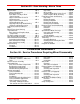
Table of Contents IMPORTANT INFORMATION Section 1A - General Information How To Use This Manual . . . . . . . . . . . . . . . Page Numbering . . . . . . . . . . . . . . . . . . . How to Read a Parts Manual . . . . . . . . . . . Introduction . . . . . . . . . . . . . . . . . . . . . . . . . . . Directional References . . . . . . . . . . . . . . . . . 1A-2 1A-2 1A-3 1A-4 1A-4 Propeller Rotation . . . . . . . . . . . . . . . . . . . . .
REMOVAL, INSTALLATION AND ADJUSTMENT Section 2A - All Models Torque Specifications . . . . . . . . . . . . . . . . . . Lubricants / Sealants / Adhesives . . . . . . . Tools . . . . . . . . . . . . . . . . . . . . . . . . . . . . . . . . Transom Specifications . . . . . . . . . . . . . . . . Checking Transom Thickness . . . . . . . . Special Information . . . . . . . . . . . . . . . . . . . . Bravo Three Notice: Trim-In Limit Insert . . . . . . . . . . . . . . . . .
Section 3B - Gear Housing - Bravo One Specifications . . . . . . . . . . . . . . . . . . . . . . . . . 3B-2 Torque Specifications . . . . . . . . . . . . . . . 3B-2 Bearing Preloads . . . . . . . . . . . . . . . . . . . 3B-2 Gear Ratio - Teeth Per Gear (Gear Housing) . . . . . . . . . . . . . . . . . . . . 3B-2 Lubricants / Sealants / Adhesives . . . . . . . 3B-2 Tools . . . . . . . . . . . . . . . . . . . . . . . . . . . . . . . . 3B-3 Bravo One Gear Housing Exploded View . 3B-4 Drive Shaft Components . .
Section 3D - Gear Housing - Bravo Three Table of Contents . . . . . . . . . . . . . . . . . . . . . 3D-1 Specifications . . . . . . . . . . . . . . . . . . . . . . . . . 3D-2 Torque Specifications . . . . . . . . . . . . . . . 3D-2 Bearing Preloads . . . . . . . . . . . . . . . . . . . 3D-2 Gear Ratio - Teeth per Gear (Gear Housing) . . . . . . . . . . . . . . . . . . . . 3D-2 Torque Conversion Chart For Bearing Carrier . . . . . . . . . . . . . . . . . . . .
Section 4B - Service Procedures Requiring Major Disassembly Bravo Transom Assembly Specifications . 4B-2 Torque Specifications . . . . . . . . . . . . . . . 4B-2 Lubricants / Sealants / Adhesives . . . . . 4B-2 Special Tools . . . . . . . . . . . . . . . . . . . . . . . 4B-2 Bravo Transom Assembly Exploded Views . . . . . . . . . . . . . . . . . . . . . . 4B-4 Inner Transom Plate Components . . . . 4B-4 Bell Housing Components . . . . . . . . . . . 4B-5 Gimbal Ring Components . . . . . . . . . . . .
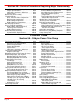
Section 5B - Trim Cylinders Specifications . . . . . . . . . . . . . . . . . . . . . . . . . Torque Specifications . . . . . . . . . . . . . . . Lubricants / Sealants / Adhesives . . . . . Special Tools . . . . . . . . . . . . . . . . . . . . . . . . . Trim Cylinder Exploded Views . . . . . . . . . . . Bravo Trim Cylinders . . . . . . . . . . . . . . . . Bravo Trim System Components . . . . . . Power Trim Hydraulic Schematic . . . . . . . . Special Information . . . . . . . . . . . . . . . . . . . .
Section 6B - Compact Hydraulic Steering Important Information About Thru-Transom Exhaust . . . . . . . . . . . . . . . . Torque Specifications . . . . . . . . . . . . . . . . . . Lubricants / Sealants / Adhesives . . . . . . . Removal . . . . . . . . . . . . . . . . . . . . . . . . . . . . . Installing The Steering Cylinder . . . . . . . . . Filling And Purging The System . . . . . . . . . Twin Station and/or Twin Cylinder . . . . . 6B-2 6B-2 6B-2 6B-3 6B-4 6B-6 6B-6 Single Station With Single Cylinder .
GENERAL INFORMATION SERVICE MANUAL NUMBER 28 IMPORTANT INFORMATION 1 Section 1A - General Information A Table of Contents How To Use This Manual . . . . . . . . . . . . . . . Page Numbering . . . . . . . . . . . . . . . . . . . How to Read a Parts Manual . . . . . . . . . . . Introduction . . . . . . . . . . . . . . . . . . . . . . . . . . . Directional References . . . . . . . . . . . . . . . . . Propeller Rotation . . . . . . . . . . . . . . . . . . . . .
IMPORTANT INFORMATION SERVICE MANUAL NUMBER 28 How To Use This Manual This manual is divided into sections that represent major components and systems. Some sections are further divided into parts that more fully describe the component. Sections and parts are listed at front of this manual. Page Numbering Two number groups appear at the bottom of each page. Following is an example and description.
GENERAL INFORMATION SERVICE MANUAL NUMBER 28 How to Read a Parts Manual Power Steering Pump Assembly 8 2 10 6 1 4 3 7 9 5 REF. NO. 1 2 3 4 5 6 7 8 9 10 PART NO. 90507A12 36- 95805 73873A1 16- 41877 57- 65607T 32- 806684 25- 89879 25- 806232 13- 35048 61990 SYM. QTY. 1 1 1 1 1 1 1 1 1 1 DESCRIPTION PUMP ASSEMBLY-Power Steering CAP PULLEY STUD V-BELT HOSE-Pressure (FITTINGS ON BOTH ENDS) O-RING O-RING LOCKWASHER (3/8 in.) CABLE TIE REF. NO. : Number shown next to part on exploded view PART NO.
IMPORTANT INFORMATION SERVICE MANUAL NUMBER 28 Introduction This comprehensive overhaul and repair manual is designed as a service guide for the MerCruiser models previously listed. It provides specific information, including procedures for disassembly, inspection, assembly and adjustment, to enable dealers and service mechanics to repair these products.
GENERAL INFORMATION SERVICE MANUAL NUMBER 28 Sterndrive Unit 10-Hour Break-In Period (New or With Replacement Gears) 1. Avoid full throttle starts. 2. DO NOT operate at any one constant speed for extended periods of time. 3. DO NOT exceed 75% of full throttle during the first 5 hours. During the next 5 hours, operate at intermittent full throttle. 4. Drive unit should be shifted into forward gear a minimum of 10 times during break-in, with run-in time at moderate rpm after each shift.
IMPORTANT INFORMATION SERVICE MANUAL NUMBER 28 THIS PAGE IS INTENTIONALLY BLANK INDEX Page 1A-6 90-863160 MAY 2000
MAINTENANCE SERVICE MANUAL NUMBER 28 IMPORTANT INFORMATION 1 Section 1B - Maintenance B Table of Contents Lubricants / Sealants / Adhesives . . . . . 1B-2 Maintenance Schedules . . . . . . . . . . . . . 1B-3 Maintenance Intervals . . . . . . . . . . . . . 1B-3 Gas Sterndrive . . . . . . . . . . . . . . . . . . . . . . 1B-3 Routine Maintenance * . . . . . . . . . . . . 1B-3 Gas Sterndrive(Continued) . . . . . . . . . . . 1B-4 Scheduled Maintenance * . . . . . . . . . 1B-4 Specifications . . . . . . . .
MAINTENANCE SERVICE MANUAL NUMBER 28 Lubricants / Sealants / Adhesives Description Part Number Quicksilver 4-Cycle 25W-40 Marine Engine Oil 92-802837A1 SAE 20W, 30W Or 40W Engine Oil Obtain Locally Quicksilver High Performance Gear Lube 92-802854A1 Extended Life Ethylene Glycol Antifreeze Obtain Locally Quicksilver Special Lubricant 101 92-13872A1 Quicksilver Engine Coupler Spline Grease 92-802869A1 Quicksilver Corrosion Guard Spray 92-802878 55 Quicksilver 2-4-C Marine Lubricant With Tefl
MAINTENANCE SERVICE MANUAL NUMBER 28 Maintenance Schedules Maintenance Intervals Maintenance intervals and tasks, as shown in this schedule, or as found in previously printed schedules, are based on an average boating application and environment. However, individual operating habits and personal maintenance preferences can have an impact on the suggested intervals. In consideration of these factors, Mercury MerCruiser has adjusted some maintenance intervals and corresponding tasks to be performed.
MAINTENANCE SERVICE MANUAL NUMBER 28 Gas Sterndrive(Continued) Scheduled Maintenance * Every Every Every 200 300 Every Every 100 Annu2 5 hours hours hours or ally or 3 or 3 years years Annually years years Touch-up power package paint and spray with Corrosion Guard. Change crankcase oil and filter. Change sterndrive unit oil and retorque connection of gimbal ring to steering shaft. Replace fuel filter(s). Check steering system and remote control for loose, missing or damaged parts.
MAINTENANCE SERVICE MANUAL NUMBER 28 Specifications Torque Specification Fastener Location lb-in. lb-ft Nm Sterndrive Unit Fill/Drain Plug 40 4.5 Sterndrive Unit Vent Plug 40 4.5 We recommend the use of Quicksilver Maintenance Products where specified. Fluid Capacities NOTICE Unit Of Measurement: U.S. Quarts (Liters) All capacities are approximate fluid measures.
MAINTENANCE SERVICE MANUAL NUMBER 28 Propeller Shaft a a a 76910 72239 77047 77046 Bravo One / Bravo Two Sterndrives a - Propeller Shaft Bravo Three Sterndrive/ Bravo XZ & XR Steering System WARNING Transom end of steering cable MUST BE fully retracted into cable housing when lubricating cable. If cable is lubricated while extended, hydraulic lock of cable could occur.
MAINTENANCE SERVICE MANUAL NUMBER 28 Tie Bar Pivot Points MODELS WITH CONTROL VALVE MOUNTED ON STARBOARD TRANSOM ASSEMBLY a a 22079 22079 Starboard Engine a - Pivot Point Port Engine MODELS WITH CONTROL VALVE MOUNTED ON PORT TRANSOM ASSEMBLY a a 22079 Starboard Engine a - Pivot Point 22079 Port Engine Transom Gimbal Housing Assembly Swivel Shaft and Gimbal Bearing b 50072 a - Gimbal Bearing Grease Fitting INDEX 90-863160 MAY 2000 Page 1B-7
MAINTENANCE SERVICE MANUAL NUMBER 28 Checking and Adding Sterndrive Oil IMPORTANT: Position sterndrive unit in DOWN/IN position so that anti-ventilation plate is level. CAUTION If more than 2 fl. oz. (59 ml) of oil is required to fill sterndrive unit, an oil leak may exist. Find and correct cause of leak before unit is placed in operation. NOTE: Sterndrive unit oil level is checked at gear lube monitor.
MAINTENANCE SERVICE MANUAL NUMBER 28 Inspection Periodically inspect lubricant for water to ensure that sterndrive unit seals are not leaking. Check for water at bottom of gear lube monitor. If a water leak is indicated the sterndrive unit must be resealed. CAUTION If more than 2 fl. oz. (59ml) of Quicksilver High Performance Gear Lube is required to fill gear lube monitor, a seal may be leaking. Find and correct cause of leak before unit is placed in operation.
MAINTENANCE SERVICE MANUAL NUMBER 28 Changing Sterndrive Oil CAUTION If any water drains from fill/drain hole a leak in sterndrive unit may exist. Find and correct cause of leak before placing unit back in operatIon. CAUTION DO NOT attempt to fill sterndrive unit through oil vent holes, as air will be trapped in sterndrive unit and unit will be damaged from lack of lubrication. 1. Bravo I: Trim sterndrive unit to full DOWN/IN position. a b 70023 a - Oil Fill/Drain Plug b - Sealing Washer 2.
MAINTENANCE SERVICE MANUAL NUMBER 28 7. Check condition of hose and hose connections. Replace as necessary. a 71990 a - Gear Lube Monitor 8. Remove sterndrive unit vent plug and fill/drain plug. Allow lubricant to drain completely. 9. If sterndrive unit is draining in full DOWN/IN position, trim to full UP/OUT position after draining drain any remaining oil from internal driveshaft housing ledges. 10.
MAINTENANCE SERVICE MANUAL NUMBER 28 General Maintenance Maintaining Power Package Exterior Surfaces Entire power package should be sprayed at recommended intervals with Quicksilver Corrosion Guard. Follow instructions on can for proper application. Entire power package should be cleaned and external surfaces that have become bare should be repainted with Quicksilver Primer and Spray Paint at recommended intervals.
MAINTENANCE SERVICE MANUAL NUMBER 28 IMPORTANT: If anti-fouling protection is required for boat hull or boat transom, copper or tin base paints, if not prohibited by law, can be used. If using copper or tin based anti-fouling paints, observe the following: • Avoid an electrical interconnection between the Mercury MerCruiser Product, Anodic Blocks, or MerCathode System and the paint by allowing a minimum of 1-1/2 in. (40 mm) UNPAINTED area on transom of the boat around these items.
MAINTENANCE SERVICE MANUAL NUMBER 28 9. After paint has dried, spray entire sterndrive with Quicksilver Corrosion Guard. Refer to SECTION 1B. CAUTION Store sterndrive unit in the full trim DOWN/IN position. U-joint bellows may develop a “set” if unit is stored in raised position and may fail when unit is returned to service. 10. If not already done, place sterndrive unit in the full trim DOWN/IN position. 11. Store battery. Refer to battery manufacturer’s instructions.
TROUBLESHOOTING SERVICE MANUAL NUMBER 28 IMPORTANT INFORMATION 1 Section 1C - Troubleshooting C Table of Contents Table of Contents . . . . . . . . . . . . . . . . . . . . . Troubleshooting . . . . . . . . . . . . . . . . . . . . . . . Sterndrive Unit Troubleshooting . . . . . . . . . Sterndrive Unit Will Not Slide Into Bell Housing . . . . . . . . . . . . . . . . . . . . . . . Drive Unit Does Not Shift Into Gear; Remote Control Shift Handle Moves . .
TROUBLESHOOTING SERVICE MANUAL NUMBER 28 Troubleshooting This section is a guide for performance and product troubleshooting. Referrals to specific sections of this manual are made where special tests or repair procedure are to be performed. Because of the relationship between Power Package components (engine and sterndrive), it will be necessary in some cases to simultaneously refer to the appropriate Engine Service Manual for further troubleshooting information.
TROUBLESHOOTING SERVICE MANUAL NUMBER 28 Drive Unit Does Not Shift Into Gear; Remote Control Shift Handle Does Not Move NOTE:For additional information on troubleshooting, refer to SECTION 2A and see “Troubleshooting Shift Problems.” Cause Special Instructions Control box not properly assembled. Properly reassemble control box. Broken or damaged linkage in control box. Repair linkage. Controls improperly adjusted-cable end guide hitting brass barrel. Adjust shift cables.
TROUBLESHOOTING SERVICE MANUAL NUMBER 28 Gear Housing Noise Cause Special Instructions Metal particles in drive unit lubricant. Disassemble, clean and inspect and replace necessary components. (Refer to SECTION 3B, 3C or 3D) Propeller incorrectly installed. Inspect mounting hardware. Install propeller correctly. Propeller shaft bent. Inspect and replace if necessary. (Refer to SECTION 3B, 3C or 3D) Incorrect gear shimming. Check gear housing backlash and pinion gear height.
TROUBLESHOOTING SERVICE MANUAL NUMBER 28 Drive Shaft Housing Noise (Continued) Cause Special Instructions Worn U-joint shaft splines and/or engine coupler splines. Remove U-joint coupling end yoke and insert into gimbal bearing and engine coupling. Rotate shaft back and forth. If play is excessive, replace U-joint coupling end yoke and/or engine coupler, as necessary. Engine alignment incorrect or engine coupler crooked. Adjust alignment. Ensure that alignment tool moves in and out of coupler freely.
TROUBLESHOOTING SERVICE MANUAL NUMBER 28 Drive Shaft Housing Noise (Continued) Cause Boat transom too thin. Thickness: 2 in. (51mm) minimum, 2-1/4 in. (57mm) maximum. Boat transom thickness uneven. This could affect engine to transom assembly alignment and is usually not detectable with alignment tool. Variation: 1/8 in. (3mm) maximum. Bell housing contacting gimbal ring. This would cause knocking in the fully trimmed IN position only. Special Instructions Add thickness to transom.
TROUBLESHOOTING SERVICE MANUAL NUMBER 28 Power Shift System Does Not React Cause Special Instructions Vacuum leaks. With engine running, check for vacuum leaks. Squirt oil on fitting and hose connections and on the shift cylinder-to-end plate joint. If oil is sucked in at any point, a vacuum leak exists. Repair leak. Improper installation. Reinstall. System Binds Cause Special Instructions Remote control. Disconnect input cable at power shift cylinder.
TROUBLESHOOTING SERVICE MANUAL NUMBER 28 Performance Troubleshooting Low WOT Engine RPM Cause Special Instructions Improper drive unit trim angle. Properly adjust drive unit trim angle. Damaged propeller. Repair or replace. Improper propeller pitch. Water test boat using a lower pitch propeller. Dirty or damaged boat bottom. Clean and/or resurface boat bottom. Drive installation too low on transom. Contact boat manufacturer for installation specifications.
TROUBLESHOOTING SERVICE MANUAL NUMBER 28 Poor Boat Performance And/Or Poor Maneuverability-Bow Too Low Cause Special Instructions Improper drive unit trim angle. Properly adjust drive unit trim angle. Boat is bow heavy. Redistribute boat load to stern. If bow overweight is caused by permanently installed fuel tank(s), contact the boat manufacturer. Boat is underpowered. Check horsepower to weight ratio. Contact the boat manufacturer.
TROUBLESHOOTING SERVICE MANUAL NUMBER 28 Power Steering Hard Steering - Helm And Cable Cause Special Instructions Damaged steering cable. Replace cable. (Refer to SECTION 2) Steering cable too short (sharp bends) or too long (loops and long bends). Select and install proper length cable. (Refer to SECTION 2A) Steering cable corroded or not lubricated. Lubricate or replace the cable. Over-lubed cable. Replace cable. RideGuide rack or rotary head not lubricated. Disassemble and lubricate.
TROUBLESHOOTING SERVICE MANUAL NUMBER 28 Compact Hydraulic Steering Important Information Whenever a troubleshooting solution calls for removal from vessel and/or dismantling of steering system components, such work must be carried out by a qualified marine mechanic. The following is offered as a guide only and neither Mercury MerCruiser nor the helm manufacturer are responsible for any consequences resulting from incorrect repairs.
TROUBLESHOOTING SERVICE MANUAL NUMBER 28 Power Trim Electrical System NOTE:Refer to “Power Trim System Wiring Diagram.” Power Trim Pump Motor Will Not Run In The OUT/UP Or IN/DOWN Direction SOLENOIDS DO NOT CLICK Cause Special Instructions Bad electrical connection at the 110 amp fuse or at the battery or the harness came Check all electrical connection points unplugged from the pump Determine cause for the blown fuse and correct before replacing fuse. 20 amp fuse blown.
TROUBLESHOOTING SERVICE MANUAL NUMBER 28 Power Trim Pump Motor Will Not Run In The OUT/UP Or IN/DOWN Direction BOTH SOLENOIDS CLICK Cause Special Instructions Faulty solenoids or loose or corroded connections. Check for battery voltage at terminals 5 while trimming OUT/UP. If no voltage is indicated, check connections 2, 3, 4 and 5 and/or replace solenoids. Pump motor brushes stuck, corroded or worn out. Clean or replace as required. Armature commutator dirty. Clean or replace armature as required.
TROUBLESHOOTING SERVICE MANUAL NUMBER 28 Power Trim Pump Motor Runs In The OUT/UP Direction, But Not In The IN/DOWN Direction IN/DOWN SOLENOID CLICKS Cause Special Instructions Loose or dirty solenoid connections. Check connections 4 and 5. Clean and/or tighten as necessary. Faulty solenoid. Check for battery voltage at terminal 5 while trimming IN/DOWN. If no voltage is indicated, replace solenoid. Faulty IN/DOWN field winding. Replace field and frame assembly.
TROUBLESHOOTING SERVICE MANUAL NUMBER 28 Trim Control OUT/UP Trim Switch Inoperative TRAILER SWITCH OPERATES Cause Special Instructions Trim limit switch lead bullet connectors loose or corroded. Clean and/or tighten connections 14, 15, 16 and 17 as necessary. Faulty trim limit switch or leads. Disconnect trim limit switch leads from trim harness. Connect a continuity meter between leads 16 and 17. Continuity should be indicated with drive unit in full IN/DOWN position.
TROUBLESHOOTING SERVICE MANUAL NUMBER 28 Power Trim System Wiring Diagram 12 11 18 b 10 8 9 a c 3 1 2 d f 4 13 e 5 7 6 g h 17 15 16 14 BLK BLU BRN GRY GRN ORN PNK PUR RED TAN WHT YEL LIT DRK = = = = = = = = = = = = = = BLACK BLUE BROWN GRAY GREEN ORANGE PINK PURPLE RED TAN WHITE YELLOW LIGHT DARK 77103 NOTE:Numbered callouts refer to Power Trim Electrical System Troubleshooting Chart.
TROUBLESHOOTING SERVICE MANUAL NUMBER 28 Power Trim Hydraulic System NOTE:Refer to “Power Trim Hydraulic Schematic.” Drive Unit Cannot Be Trimmed OUT/UP Or Trims Slowly Or With Jerky Movements Cause Special Instructions Power trim pump oil level low. Check for cause of low oil level and correct. Add oil and bleed trim system. Air in trim system. Check for cause of entry and correct. Add oil to pump and bleed air from system.
TROUBLESHOOTING SERVICE MANUAL NUMBER 28 Oil Foams Out Of Pump Fill/Vent Screw Cause Special Instructions Contaminated oil. Flush system with clean oil refill pump and bleed trim system. Oil level low. Check for cause of low oil level and correct. Add oil to pump and bleed system. Sterndrive Unit Cannot Be Lowered From UP Position Or Lowers With Jerky Movements Cause Special Instructions Air in trim system. Check for cause of entry. Fill and bleed trim system. Low oil level. Add oil.
TROUBLESHOOTING SERVICE MANUAL NUMBER 28 Sterndrive Will Not Stay In The Trimmed OUT/UP Position When Underway Cause Special Instructions Air in trim system. Check for cause of entry. Fill and bleed system. Leaky poppet valve. Install repair kit for poppet valve 1. Sterndrive Unit Trails OUT/UP On Deceleration Or When Shifting Into Reverse UNIT THUMPS WHEN SHIFTING Cause Special Instructions Trim cylinders(s) leaking internally. Test.
TROUBLESHOOTING SERVICE MANUAL NUMBER 28 Trim Motor Runs But Does Not Pump Oil Cause Special Instructions Broken coupler between the pump and the Replace the coupler. motor. Plugged pick-up screens. Replace pick-up screens. Trim Pump Runs Slowly In Both Directions Cause Check the condition of the oil It may be contaminated and thick like honey. Special Instructions Remove the reservoir and clean out the contaminated oil.
TROUBLESHOOTING SERVICE MANUAL NUMBER 28 Power Trim Hydraulic Schematic 9 1 2 4 3 6 5 8 7 5 73552 1 2 3 4 5 6 7 8 9 - Shuttle - Pump Adaptor - UP/OUT Pressure Relief Valve - Thermal Relief Valve - Trim Cylinder - IN/DOWN Pressure Relief Valve - UP/OUT Hose - IN/DOWN Hose - Poppet Valves INDEX 90-863160 MAY 2000 Page 1C-21
TROUBLESHOOTING SERVICE MANUAL NUMBER 28 Auto Trim II Electrical System NOTE:Refer to “Auto Trim II System Wiring Diagram.” Pump Motor Will Not Run UP Or DOWN In Either Manual Or Auto Mode SOLENOIDS CLICK Cause Special Instructions Pump positive battery cable connection loose or corroded. Check cable 14. 110 amp fuse blown or loose or corroded solenoid connection. Check for voltage at terminal 5. Pump motor brushes stuck, corroded or worn out. Clean or replace. Armature commutator dirty.
TROUBLESHOOTING SERVICE MANUAL NUMBER 28 SOLENOIDS DO NOT CLICK Cause Special Instructions Pump negative battery cable loose, corroded or damaged. Check cable 13 for damage or a loose or corroded connection. Mode switch wiring harness connector is loose at pump. Secure connection 47. Faulty thermal circuit breaker in pump motor. Open circuit in mode switch wiring harness. Connect a jumper wire between terminals 1 and 7.
TROUBLESHOOTING SERVICE MANUAL NUMBER 28 Pump Motor Will Not Stop Running Down In Auto Mode TRIM UP/OUT SWITCH AND TRAILER SWITCH INOPERATIVE IN MANUAL MODE NOTE:An internal timer in the control module stops the pump motor 50 seconds after this problem condition occurs. Cause Special Instructions Loose or dirty solenoid connection. Check connections 7 and 8. Faulty solenoid. Check for voltage at terminal 8 while trimming UP (in MANUAL mode).
TROUBLESHOOTING SERVICE MANUAL NUMBER 28 Trim System Completely Inoperative In Manual Mode AUTO MODE FUNCTIONS PROPERLY Cause Special Instructions Faulty mode switch. Check for voltage at terminal 26 with mode switch in MANUAL mode. If no voltage is indicated, replace switch. Open circuit in wiring harness. Check leads 27 and 33 for loose or corroded connections or damage.
TROUBLESHOOTING SERVICE MANUAL NUMBER 28 Pump Motor Will Run DOWN, But Not UP In Auto Mode MANUAL MODE FUNCTIONS PROPERLY Cause Special Instructions Open circuit in control module sense lead. Check lead 17 for loose or corroded connections or damage. Faulty control module. Replace. Pump Motor Will Run UP, But Not DOWN In Auto Mode MANUAL MODE FUNCTIONS PROPERLY Cause Faulty mode switch. Open circuit in wiring. Faulty control module.
TROUBLESHOOTING SERVICE MANUAL NUMBER 28 Trim UP/OUT Switch Inoperative In Manual Trim Control TRIM DOWN/IN SWITCH FUNCTIONS, AUTO MODE FUNCTIONS PROPERLY Cause Special Instructions Trim 20 amp fuse “43” blown (if equipped). Determine cause for blown fuse and correct before replacing fuse. Open in power supply lead to trim and trailer switch. Check voltage at terminal 44. If no voltage is indicated, check lead 45 for a poor connection or damage.
TROUBLESHOOTING SERVICE MANUAL NUMBER 28 Auto Trim II System Wiring Diagram 18 1 14 8 7 6 2 5 9 13 47 10 12 3 4 48 11 46 41 39 42 24 43 40 45 37 27 34 38 36 21 22 25 44 33 19 23 26 15 16 20 28 29 30 31 17 32 35 22178 INDEX Page 1C-28 90-863160 MAY 2000
TROUBLESHOOTING SERVICE MANUAL NUMBER 28 Corrosion Protection NOTE:Refer to “MerCathode Controller Wiring Diagram.” Corrosion On Underwater Parts, Without MerCathode Or Impressed Current Protection Cause Special Instructions Sacrificial anode(s) consumed. Replace anode(s) when 50% consumed. Stainless steel propeller installed. Add MerCathode (impressed current protection) or additional sacrificial anodes. Sacrificial anode(s) not grounded to drive.
TROUBLESHOOTING SERVICE MANUAL NUMBER 28 Corrosion On Underwater Parts, With MerCathode Or Impressed Current Protection DRIVE CORRODING Cause Special Instructions Poor connection between reference electrode (BRN) lead or anode (ORN) lead and MerCathode controller. Clean and/or tighten connection. Repair wiring. Faulty MerCathode reference electrode. Disconnect reference electrode lead (BRN) from the controller “R” terminal.
TROUBLESHOOTING SERVICE MANUAL NUMBER 28 DRIVE CORRODING - CONTINUED Cause No power to MerCathode controller. Special Instructions Connect positive (+) lead of volt meter (set on 0-20 volt scale) to positive (+) terminal on the controller and negative (-) volt meter lead to negative (-) terminal. Meter should indicate battery voltage. Check for blown fuse (if equipped) on a standard MerCathode system. Clean the connection or repair wiring as required. Check the fuse in the hot lead. Check battery.
TROUBLESHOOTING SERVICE MANUAL NUMBER 28 Corrosion On Underwater Parts, With MerCathode Or Impressed Current Protection DRIVE OVER-PROTECTED Cause Faulty MerCathode reference electrode. Faulty MerCathode controller. Stray current corrosion (electrical current leaves a metal conductor and creates a path through the water). Poor connection between the MerCathode reference electrode lead (BRN) and the “R” terminal on the controller.
TROUBLESHOOTING SERVICE MANUAL NUMBER 28 Testing Procedure for Corrosion Protection 1. Unplug shore power (if equipped). 2. Measure hull potential with silver/silver chloride reference electrode and digital volt/ohm meter. READINGS Saltwater Freshwater Potential Diagnosis Below 850 millivolts Drive is corroding. (Refer to “Drive Corroding”) Between 850 - 1100 millivolts Drive is protected Above 1100 millivolts Drive is overprotected.
TROUBLESHOOTING SERVICE MANUAL NUMBER 28 MerCathode Controller a b c 73596 a - Controller b - 20 Amp Fuse c - Electrode INDEX Page 1C-34 90-863160 MAY 2000
TROUBLESHOOTING SERVICE MANUAL NUMBER 28 THIS PAGE IS INTENTIONALLY BLANK INDEX 90-863160 MAY 2000 Page 1C-35
TROUBLESHOOTING SERVICE MANUAL NUMBER 28 THIS PAGE IS INTENTIONALLY BLANK INDEX Page 1C-36 90-863160 MAY 2000
REMOVAL, INSTALLATION AND ADJUSTMENTS SERVICE MANUAL NUMBER 28 REMOVAL, INSTALLATION AND ADJUSTMENTS Section 2A - All Models Table of Contents Torque Specifications . . . . . . . . . . . . . . . . . . Lubricants / Sealants / Adhesives . . . . . . . Tools . . . . . . . . . . . . . . . . . . . . . . . . . . . . . . . . Transom Thickness and Surface . . . . . . . . Special Information . . . . . . . . . . . . . . . . . . . . Bravo Three Notice: Trim-In Limit Insert . . . . . . . . . . . . . . . . .
REMOVAL, INSTALLATION AND ADJUSTMENTS SERVICE MANUAL NUMBER 28 Torque Specifications NOTE: Securely tighten all fasteners not listed below. Fastener Location lb-ft Nm Exhaust Pipe to Gimbal Housing Screws 23 31 Block Off Plate to Gimbal Housing Screws 23 31 55 75 Propeller Nut 1 Drive Unit Shift Cable Locknut lb-in.
REMOVAL, INSTALLATION AND ADJUSTMENTS SERVICE MANUAL NUMBER 28 Transom Thickness and Surface IMPORTANT: Transom thickness and surface plane (flatness) must be controlled where the sterndrive unit mounts. Transom thickness and surface must conform to the following: Transom Specifications Thickness Between 2 - 2-1/4 in. (51 - 57 mm) Parallelism Inner and outer surfaces must be parallel within 1/8 in.
REMOVAL, INSTALLATION AND ADJUSTMENTS SERVICE MANUAL NUMBER 28 Special Information Bravo Three Notice: Trim-In Limit Insert It has been brought to our attention that some boats (predominantly deep-V heavy boats) will roll up on their side under certain, specific, operating conditions. The roll can be to either port or starboard and may be experienced while moving straight ahead or while making a turn.
REMOVAL, INSTALLATION AND ADJUSTMENTS SERVICE MANUAL NUMBER 28 1. Ensure that the Trim-In Limit Insert is positioned as shown for the appropriate Bravo model. a 75157 Bravo One and Two (Positioned Forward) a 75158 Bravo Three (Positioned Aft) a - Trim-In Limit Insert IMPORTANT: The position of the Trim-In Limit Insert on the Bravo Three sterndrive unit should only be changed after the boat has been properly tested.
REMOVAL, INSTALLATION AND ADJUSTMENTS SERVICE MANUAL NUMBER 28 Sterndrive Unit Removal 1. Shift remote control into neutral. 2. Place the drive unit to the full UP/OUT position. CAUTION Avoid speedometer hose fitting damage. Disconnect the speedometer hose fitting from the drive shaft housing before removing the sterndrive unit. 3. Disconnect the speedometer hose fitting from the drive shaft housing. 22025 4.
REMOVAL, INSTALLATION AND ADJUSTMENTS SERVICE MANUAL NUMBER 28 5. Remove the locknuts holding the sterndrive onto the bell housing, then remove the sterndrive unit. b a 22031 a - Locknuts (6) And Flat Washers (5) b - Ground Plate (Flat Washer Not Used Here) d c 22025 c - Shift Linkage Jaws d - Shift Cable End 6. Ensure the shift cable linkage jaws open and release the shift cable end.
REMOVAL, INSTALLATION AND ADJUSTMENTS SERVICE MANUAL NUMBER 28 Transom Assembly Removal 1. Remove engine (Refer to appropriate engine service manual). 2. Completely disconnect the power steering assembly. a. Disconnect the rear clevis pin from the steering lever. b. Disconnect forward clevis pin from steering cable end. c. Holds flats on cable guide in vertical position with suitable wrench. Loosen coupler nut and remove steering cable.
REMOVAL, INSTALLATION AND ADJUSTMENTS SERVICE MANUAL NUMBER 28 3. Disconnect trim limit switch wires. 4. Remove power trim pump hydraulic hoses and disconnect trim limit switch wires. Cap hoses and plug pump fitting holes. c b a 76631 a - Sta-Strap b - Trim Limit Switch Wires c - Hydraulic Hoses 5. Remove exhaust pipe. NOTE: For through transom exhaust, it is not necessary to remove the block-off plate unless the gasket/mating surface is leaking or the exhaust system is to be modified.
REMOVAL, INSTALLATION AND ADJUSTMENTS SERVICE MANUAL NUMBER 28 6. Remove the continuity wire from the steering lever. b c a 22028 a - Steering Lever b - Screw c - Continuity Wire 7. Disconnect the speedometer hoses. a 70015 a - Speedometer Fitting 8. Remove seawater intake hose. b a d c a b c d 76636 - Seawater Intake Hose - Seawater Pickup Outlet - Bolts and Star Washers - Gear Lube Monitor Hose 9. Remove seawater pickup outlet. 10. Remove gear lube monitor hose.
REMOVAL, INSTALLATION AND ADJUSTMENTS SERVICE MANUAL NUMBER 28 11. On Diesel Models with Water Bypass Fitting - Remove fitting. a 72045 a - Water Bypass Fitting 12. Remove transom locknuts and washers. a a 73902 a - Locknuts and Washers (8) 13. Separate the inner transom plate from the gimbal housing assembly.
REMOVAL, INSTALLATION AND ADJUSTMENTS SERVICE MANUAL NUMBER 28 Transom Assembly Installation CAUTION Avoid continuity wire failure. Position the steering lever ground wire as shown or the wire may fatigue and break. b c a 22028 a - Steering Lever b - Transom Plate c - Continuity Wire 1. Install the transom assembly. Tighten locknuts evenly, starting from the center and working outward. Torque to 23 lb-ft (31 Nm).
REMOVAL, INSTALLATION AND ADJUSTMENTS SERVICE MANUAL NUMBER 28 IMPORTANT: Hose must not come in contact with steering system components or the engine coupler and drive shaft. 2. Connect gear lube monitor hose. 3. Install water inlet fitting with gasket. Torque bolts and star washers to 45 lb-in. (5 Nm). c a d b a b c d 76640 - Hose To Gear Lube Monitor - Hose Clamp - Water Inlet Fitting - Bolts And Star Washers 4.
REMOVAL, INSTALLATION AND ADJUSTMENTS SERVICE MANUAL NUMBER 28 5. On D7.3L Diesel Models with Water Bypass Fitting - Apply Perfect Seal to threads and install fitting. Tighten securely and position as shown. a 76656 a - Water Bypass Fitting 6. Connect water hoses to appropriate fittings. Tighten hose clamps securely. b a 76641 a - Seawater Hose To Engine Seawater Pump b - Seawater Pickup Hose 7. Connect the speedometer hose to the speedometer fitting.
REMOVAL, INSTALLATION AND ADJUSTMENTS SERVICE MANUAL NUMBER 28 IMPORTANT: Exhaust pipe or block-off plate and gimbal housing mating surface, must be clean and free of nicks and scratches and O-ring must be properly seated in groove, or water may leak into boat.
REMOVAL, INSTALLATION AND ADJUSTMENTS SERVICE MANUAL NUMBER 28 8. Through the prop exhaust models: Install exhaust pipe. Torque bolts to 23 lb-ft (31 Nm).
REMOVAL, INSTALLATION AND ADJUSTMENTS SERVICE MANUAL NUMBER 28 9. Through the transom exhaust models: Install exhaust block-off plate, if removed. Torque bolts to 23 lb-ft (31 Nm). b a 76638 a - Block-Off Plate b - Bolts IMPORTANT: Make hydraulic hose connections as quick as possible to prevent oil from leaking out of the system. CAUTION Installing trim pump hoses improperly can damage the hose fittings and cause leaks or loose lines. Do not cross thread or overtighten the hose fittings. 10.
REMOVAL, INSTALLATION AND ADJUSTMENTS SERVICE MANUAL NUMBER 28 12. Connect the power steering assembly to the transom. a. Lubricate bushings with Special Lubricant 101. a 71901 a - Bushings b. Slide the power steering cylinder bushings between the transom mounting brackets. Tighten the two pivot bolts by hand. At the same time, move the steering assembly slightly to ensure proper pin engagement into the pivot bushings. c. Ensure that the washer tangs straddle the ridges on the inner transom plate.
REMOVAL, INSTALLATION AND ADJUSTMENTS SERVICE MANUAL NUMBER 28 16. Connect the cable end to the clevis with the forward clevis pin. Secure the pin in the clevis with a cotter pin. Spread the cotter pin ends. a b f d e g a b c d e f g c 71901 - Rear Clevis Pin - Clevis - Cotter Pin - Steering Cable End - Cable Guide - Forward Clevis Pin - Coupler Nut 17. Using a suitable wrench hold the flat surfaces on the cable guide tube in the vertical position.
REMOVAL, INSTALLATION AND ADJUSTMENTS SERVICE MANUAL NUMBER 28 19. Attach both hydraulic hose fittings. a. Torque both fittings to 23 lb-ft (31 Nm). Route hoses as appropriate to avoid contact with the steering system components.
REMOVAL, INSTALLATION AND ADJUSTMENTS SERVICE MANUAL NUMBER 28 21. Connect the MerCathode wires at the MerCathode controller. a a b c d b c d 22232 - ORN Lead - From Electrode on Transom Assembly - RED/PUR Lead - Connect (Other End) To Positive (+) Battery Terminal - BLK Lead - From Engine Harness - BRN Lead - From Electrode On Transom Assembly 22. Apply a thin coat of Liquid Neoprene to all electrical connections. 23. Connect the trim limit switch wires.
REMOVAL, INSTALLATION AND ADJUSTMENTS SERVICE MANUAL NUMBER 28 Sterndrive Unit Installation 1. Install and align the engine. Refer to the appropriate engine service manual. NOTE: If the engine was removed and the shift cable was disconnected, reinstall and adjust the shift cable before proceeding. 2. Place the remote control shift lever in the neutral position. 3. Lubricate the bell housing studs with Quicksilver 2-4-C Marine Lubricant with Teflon. a a 76674 a - Bell Housing Studs 4.
REMOVAL, INSTALLATION AND ADJUSTMENTS SERVICE MANUAL NUMBER 28 IMPORTANT: The edge of the U-joint bellows acts as a seal between the bell housing and the drive shaft housing. Ensure that the surface is not damaged. a 24725 a - Drive Shaft Bellows Edge 5. Inspect the U-joint bellows for cracks, nicks, and cleanliness. Replace or clean the bellows as necessary. 6. Lubricate the O-ring seals on the face of the drive shaft housing.
REMOVAL, INSTALLATION AND ADJUSTMENTS SERVICE MANUAL NUMBER 28 7. Pull out the shift linkage as far as possible. The jaws will open. Lubricate the underside of the lower lip of the shift linkage assembly with Quicksilver Special Lubricant 101. b a c c 22025 a - Shift Linkage Assembly b - Jaws Open c - Underside of Lower Lip 8. Ensure that shift lever is in the neutral position.
REMOVAL, INSTALLATION AND ADJUSTMENTS SERVICE MANUAL NUMBER 28 NOTE: If the shift cable does not line up to properly enter the shift linkage jaws, use your hand to guide the cable into place while installing the sterndrive unit. a b 22025 a - Shift Linkage Jaws b - Shift Cable 9. Install the sterndrive unit. a. Position the trim cylinders so that they point straight backwards (aft). b. Align the U–joint shaft with the bell housing bore.
REMOVAL, INSTALLATION AND ADJUSTMENTS SERVICE MANUAL NUMBER 28 IMPORTANT: On Bravo One, Two and Three Models, the Trim-In Limit Insert must be properly positioned before installing the trim cylinder anchor pin in the following steps. NOTE: Ensure that the Trim-In Limit Insert is reinstalled in the same position that it was in prior to removal of the sterndrive unit. If you are not sure of it’s original position, contact the boat manufacturer for their recommendation.
REMOVAL, INSTALLATION AND ADJUSTMENTS SERVICE MANUAL NUMBER 28 13. Place a large I.D. flat washer and bushing on each end of the anchor pin. Be sure to install the bushings with the small diameter end facing outward. b a c c 22029 a - Anchor Pin b - Large I.D. Washers c - Bushings 14. Loosen the nuts which secure the trim cylinders to the forward anchor pins. Move the cylinder pivot ends outward and place them over the aft anchor pin. 15.
REMOVAL, INSTALLATION AND ADJUSTMENTS SERVICE MANUAL NUMBER 28 18. Attach the speedometer hose fitting to the sterndrive unit. a. Raise the sterndrive unit to gain access to the area between the gimbal housing and the sterndrive unit. Locate the opening in the forward end of the anti-ventilation plate. b. Insert the speedometer hose fitting into the opening. a b 22025 a - Speedometer Hose Fitting b - Opening c. With the fitting fully seated, turn the handle clockwise to a tightly seated position.
REMOVAL, INSTALLATION AND ADJUSTMENTS SERVICE MANUAL NUMBER 28 Shift Cable Installation and Adjustment NOTE: Using Adjustment Tool (91-12427), shift cables can be adjusted with or without the sterndrive installed. IMPORTANT: Front propeller on Bravo Three sterndrive unit is always LH rotation and rear propeller is always RH rotation. Shift cable end guide must move in direction “A”, when control lever is placed in FORWARD gear position.
REMOVAL, INSTALLATION AND ADJUSTMENTS SERVICE MANUAL NUMBER 28 3. Install sterndrive unit shift cable. a b c 71658 a - Washers (2) b - Locknut-Tighten Until Contact, Then Loosen 1 Turn c - Cotter Pin-Insert from Top and Spread Both Ends 4. Place adjustment tool over sterndrive unit shift cable, as shown. Hold tool in place over the barrel retainer with a piece of tape. 71659 5. Locate center of remote control and control cable play (backlash). a. Shift remote control to NEUTRAL. b.
REMOVAL, INSTALLATION AND ADJUSTMENTS SERVICE MANUAL NUMBER 28 6. Adjust control cable as follows: a. Temporarily install control cable end guide into shift lever and insert anchor pin. b. Adjust control cable barrel so that hole in barrel centers with vertical centerline of stud. Ensure that backlash center mark is aligned with edge of control cable end guide.
REMOVAL, INSTALLATION AND ADJUSTMENTS SERVICE MANUAL NUMBER 28 9. Shift remote control lever into full forward position. Rear slot in tool should fit over shift lever stud. RH ROTATION BRAVO ONE AND TWO, AND ALL BRAVO THREE MODELS: Rear slot in tool should fit over shift lever stud. LH ROTATION BRAVO ONE AND TWO MODELS: Forward slot in tool should fit over shift lever stud. If slot does not fit over stud, loosen shift lever stud and slide stud up or down, until slot in tool fits over stud.
SERVICE MANUAL NUMBER 28 REMOVAL, INSTALLATION AND ADJUSTMENTS Troubleshooting Shift Problems NOTE: The following information is provided to assist an installer in troubleshooting, if hard shifting or chucking/racheting is encountered when shifting into forward gear. 1. When installing the control box in the side panel of the boat, make sure that the cables have enough clearance to operate. This is necessary because the cables move up and down when the shift handle is moved.
REMOVAL, INSTALLATION AND ADJUSTMENTS SERVICE MANUAL NUMBER 28 5. Be sure the cable is not permanently kinked. 6. Make sure there is proper clearance for cable movement when the control box is installed in the side panel. The cables must have room to move up and down when the control handle is shifted into either forward or reverse. 7.
DRIVE SHAFT HOUSING SERVICE MANUAL NUMBER 28 STERNDRIVE UNIT Section 3A - Drive Shaft Housing Table of Contents Specifications . . . . . . . . . . . . . . . . . . . . . . . . . 3A-2 Torque Specifications . . . . . . . . . . . . . . . 3A-2 Tools . . . . . . . . . . . . . . . . . . . . . . . . . . . . . . 3A-2 Bearing Preloads . . . . . . . . . . . . . . . . . . . 3A-3 Lubricants / Sealants / Adhesives . . . . . 3A-3 Drive Shaft Housing Exploded View . . . . . 3A-4 Complete Housing . . . . . . . . . . . .
DRIVE SHAFT HOUSING SERVICE MANUAL NUMBER 28 Specifications Torque Specifications Fastener Location Shift Cam Assembly Locknuts lb-in.
DRIVE SHAFT HOUSING SERVICE MANUAL NUMBER 28 Bearing Preloads Description lb-in. Nm U-joint Bearings (New) 8 .9 U-joint Bearings (Used)* 5 .6 * Bearings are used if spun once under load.
DRIVE SHAFT HOUSING SERVICE MANUAL NUMBER 28 Drive Shaft Housing Exploded View Complete Housing E 9 2 3 10 1 11 4 B 5 35 D 12 13 6 7 8 15 A 14 17 29 23 22 18 C 30 16 19 21 20 F A 24 28 25 31 33 34 32 F 27 26 76799 INDEX Page 3A-4 90-863160 MAY 2000
DRIVE SHAFT HOUSING SERVICE MANUAL NUMBER 28 1 - Top Cover 2 - Screw (4) 3 - Flat Washer (4) 4 - O-ring 5 - Bearing Sleeve 6 - Needle Bearing 7 - Thrust Race (Shim) 8 - Thrust Bearing 9 - Clutch Assembly 10 - Thrust Bearing 11 - Thrust Race (shim) 12 - Needle Bearing 13 - Bearing Sleeve 14 - O-ring 15 - O-ring 16 - O-ring 17 - Shifter Shaft Bushing-Upper 18 - Shifter Shaft Bushing-Lower 19 - Shifter Shaft Seal 20 - Vent Plug Seal 21 - Vent Plug 22 - O-ring 23 - U-joint Assembly 24 - Drive Shaft Housing 2
DRIVE SHAFT HOUSING SERVICE MANUAL NUMBER 28 Exploded Parts View (Clutch) 1 A 2 3 A 4 8 4 5 6 A 7 5 76668 1 2 3 4 A - Keepers - Collar - Upper Gear Assembly - Thrust Bearings 5 6 7 8 - Garter Springs - Clutch - Lower Gear Assembly - Shaft - Quicksilver High Performance Gear Lube INDEX Page 3A-6 90-863160 MAY 2000
DRIVE SHAFT HOUSING SERVICE MANUAL NUMBER 28 Exploded Parts View (Shifter) 2 C 1 3 4 A 5 7 10 6 8 9 11 B 13 12 73363 1 2 3 4 5 6 7 - Socket Screws - Shifter Shaft - Screws - Upper Shift Cam - Yoke - Spacers - Lower Shift Cam 8 - Locknuts 9 - Link Bar 10 - Latch 11 - Shift Lever 12 - Flat Washer 13 - Cotter Pin A - Quicksilver High Performance Gear Lube B - Quicksilver Special Lubricant 101 C - Permalock 115 INDEX 90-863160 MAY 2000 Page 3A-7
DRIVE SHAFT HOUSING SERVICE MANUAL NUMBER 28 Standard Bravo U-joint Assembly 1 10 9 7 5 19 8 D A 6 C 4 1 2 3 C A 18 C 16 17 B 16 15 13 11 14 12 1 - Locknut 2 - Washer 3 - Pinion Gear 4 - Bearing (Smaller OD) 5 - Bearing (Smaller ID) 6 - Spacer 7 - Bearing Cup (Larger ID) 8 - Bearing Larger OD) 9 - Sealing Ring 10 - O-Ring 73364 11 - Beveled Washer 12 - Oil Seal 13 - Oil Seal Carrier 14 - Ring Nut 15 - Yoke 16 - Cross and Bearing 17 - Socket 18 - Yoke 19 - O-rings (3) A - Quicksil
DRIVE SHAFT HOUSING SERVICE MANUAL NUMBER 28 Bravo X, XZ, XR and Diesel Bravo U-joint Assembly A C A 8 D 7 6 C 5 4 1 2 18 C 3 17 B 16 15 14 13 12 9 1 2 3 4 5 6 7 8 9 10 11 - Locknut - Washer - Pinion Gear - Bearing Cup (Smaller OD) - Bearing (Smaller ID) - Spacer - Bearing Cup (Larger ID) - Bearing Larger OD) - Thrust Washer 76856 10 - Oil Seal 11 - O-Ring 12 - Retainer Nut 13 - Yoke 14 - Cross and Bearing 15 - Socket 16 - Cross and Bearing 17 - Yoke 18 - O-rings (3) A - Quicksilver
DRIVE SHAFT HOUSING SERVICE MANUAL NUMBER 28 Drive Shaft Housing and Gear Case Separation Drive Unit Gear Ratio Identification All drive unit gear ratios are identified on each drive in two places. It is important to note the ratio of the drive unit before proceeding with any repairs. The first place to look is on the decal on the port side of the drive housing. It will have a number such as (1.50R) and then the seal number. The second place to look will be on the universal joint splined yoke.
DRIVE SHAFT HOUSING SERVICE MANUAL NUMBER 28 NUMBER OF TEETH PER GEAR - DRIVE SHAFT HOUSING RATIO DRIVE DRIVEN 2.20:1 23 30 2.00:1 27 32 1.81:1 27 29 1.65:1 27 32 1.50:1 27 29 Bravo Three U-JOINT IDENTIFICATION RATIO U-JOINT SHAFT MARKING 2.43:1 N 2.20:1 K 2.00:1 B 1.81:1 G 1.65:1 C 1.50:1 F 1.36:1 P NUMBER OF TEETH PER GEAR - DRIVE SHAFT HOUSING RATIO DRIVE DRIVEN 2.43:1 23 30 2.20:1 23 30 2.00:1 27 32 1.81:1 27 29 1.65:1 27 32 1.50:1 27 32 1.
DRIVE SHAFT HOUSING SERVICE MANUAL NUMBER 28 NUMBER OF TEETH PER GEAR - DRIVE SHAFT HOUSING RATIO DRIVE DRIVEN 1.50:1 27 32 1.36:1 27 29 Bravo XR U-JOINT IDENTIFICATION RATIO U-JOINT SHAFT MARKING 1.50:1 R NUMBER OF TEETH PER GEAR - DRIVE SHAFT HOUSING RATIO DRIVE DRIVEN 1.50:1 16 19 Diesel Bravo One X U-JOINT IDENTIFICATION RATIO U-JOINT SHAFT MARKING 1.65:1 C 1.50:1 F 1.36:1 H NUMBER OF TEETH PER GEAR - DRIVE SHAFT HOUSING RATIO DRIVE DRIVEN 1.65:1 23 30 1.
DRIVE SHAFT HOUSING SERVICE MANUAL NUMBER 28 NUMBER OF TEETH PER GEAR - DRIVE SHAFT HOUSING RATIO DRIVE DRIVEN 2.20:1 23 30 2.00:1 27 32 1.81:1 27 29 1.65:1 27 32 1.50:1 27 29 Diesel Bravo Three X U-JOINT IDENTIFICATION RATIO U-JOINT SHAFT MARKING 2.43:1 N 2.20:1 K 2.00:1 B 1.81:1 G 1.65:1 C 1.50:1 F 1.36:1 P NUMBER OF TEETH PER GEAR - DRIVE SHAFT HOUSING RATIO DRIVE DRIVEN 2.43:1 23 30 2.20:1 23 30 2.00:1 27 32 1.81:1 27 29 1.65:1 27 32 1.
DRIVE SHAFT HOUSING SERVICE MANUAL NUMBER 28 Separate Housings 1. Remove, empty and clean gear lube monitor. 2. Drain drive unit at location “a” or “b,” as applicable, by removing fill/drain screw. b a 22103 a - Fill/Drain Screw (Bravo Two) b - Fill/Drain Screw (Bravo One) 3. Remove vent plug. a 50072 a - Vent Screw 4. Bravo One, Bravo XZ, Bravo XR, and Diesel Bravo One X: a. Remove rubber plug.
DRIVE SHAFT HOUSING SERVICE MANUAL NUMBER 28 b. Remove anodic plate. a b 76800 a - Rubber Plug b - 1/2 in. Bolt c. Remove gear case from drive shaft housing. a b 76801 a - 6 Nuts and Washers (3 Each Side) b - Bolt (Located In Anodic Cavity) 5. Bravo Two and Diesel Bravo Two X: a. Remove gear case from drive shaft housing.
DRIVE SHAFT HOUSING SERVICE MANUAL NUMBER 28 6. Bravo Three and Diesel Bravo Three X: a. Remove gear case from drive shaft housing.
DRIVE SHAFT HOUSING SERVICE MANUAL NUMBER 28 Drive Shaft Housing Disassembly 1. Shift drive unit to the neutral detent position. 2. Remove rear cover by removing screws. Do not replace vent screw until reassembly. c a b 76805 a - Screws b - Rear Cover c - Vent Hole 3. Remove shift linkage cap screw. a b 76806 a - Shift Linkage Cap Screw b - Hex Wrench 4. Install shift handle tool into shift lever and shifter shaft to aid in removing shift cam cap screw.
DRIVE SHAFT HOUSING SERVICE MANUAL NUMBER 28 5. Remove bolts and lift top cover. a b 76835 a - Bolts (4) b - Cover 6. Install shift handle tool in shifter shaft and lift shaft straight out.
DRIVE SHAFT HOUSING SERVICE MANUAL NUMBER 28 7. Remove shift linkage assembly. a. Rotate link bar 1/4 turn clockwise. b. Pull linkage assembly out. If linkage binds; move assembly from side to side while pulling. a 76837 a - Shift Linkage 8. Remove yoke and cam assembly.
DRIVE SHAFT HOUSING SERVICE MANUAL NUMBER 28 9. Loosen retainer nut and remove pinion and U-joint assembly using U-joint retainer wrench.
DRIVE SHAFT HOUSING SERVICE MANUAL NUMBER 28 10. Remove upper thrust race (shim) and thrust bearing. NOTE: In steps 10 and 12, be sure to note proper order and position of thrust races, thrust bearings and clutch assembly for later reassembly. a b 76841 a - Upper Thrust Race b - Thrust Bearing 11. Remove clutch and gear assembly.
DRIVE SHAFT HOUSING SERVICE MANUAL NUMBER 28 12. Remove lower thrust race (shim) and thrust bearing. b a 50341 76841 a - Lower Thrust Race b - Thrust Bearing Shifter Repair 1. Remove latch from link bar. a b 22100 a - Latch b - Link Bar 2. Remove link bar from shift lever. Discard cotter pin.
DRIVE SHAFT HOUSING SERVICE MANUAL NUMBER 28 3. Remove ball detent canister and compression spring. b a 22100 a - Ball Detent Canister b - Compression Spring 4. Disassemble yoke and cam assembly.
DRIVE SHAFT HOUSING SERVICE MANUAL NUMBER 28 5. Remove shifter shaft upper O-ring. a 76843 a - O-ring 6. Remove shifter shaft upper bushings using tool.
DRIVE SHAFT HOUSING SERVICE MANUAL NUMBER 28 7. Remove shifter shaft lower bushing and oil seal using tool. c a b 22459 22223 a - Shift Shaft Lower Bushing b - Oil Seal c - Bushing Removal Tool (91-17273) Shifter Inspection NOTE: Use exploded parts views as reference. 1. Shift link bar and shift lever for: • Damaged or bent parts • Worn jaw area • Excessively worn detent area on shift lever 2. Ball detent canister for: • Broken springs • Ball out of canister 3.
DRIVE SHAFT HOUSING SERVICE MANUAL NUMBER 28 Shifter Reassembly 1. Install shifter shaft lower bushing and oil seal as follows: a. Install lower bushing part way into bore as shown. a a 22223 22459 a - Lower Bushing b. Place oil seal onto bearing and seal driver with lip of seal facing upward. Apply Loctite 271 to outside diameter of seal before installation. a 22459 b 22263 a - Oil Seal b - Seal Driver (91-17275A1) c. Place bearing and seal driver with oil seal into bore from bottom.
DRIVE SHAFT HOUSING SERVICE MANUAL NUMBER 28 d. Pull oil seal and bushing into place by turning screw clockwise until tool bottoms out on casting. (Top and Bottom). 22223 22459 e. Loosen screw and remove tool. 2. Install shift shaft upper bushings as follows: a. Install bushing into bore so that bushing is flush with bottom of bore, as shown. a 22223 22459 a - Bushing 3. Assemble yoke and shift cam assembly. Coat contact surfaces with gear lube.
DRIVE SHAFT HOUSING SERVICE MANUAL NUMBER 28 4. Torque locknuts to 80 lb-in. (9 Nm).
DRIVE SHAFT HOUSING SERVICE MANUAL NUMBER 28 5. Apply small amount of Special Lubricant 101 to compression spring and ball detent canister and install into rear cover. a b 22100 a - Compression Spring b - Detent Canister 6. Install link bar to shift lever. Install cotter pin and spread ends. e d a c b 22099 a b c d e - Link Bar - Shift Lever - Clevis Pin - Washer - Cotter Pin 7. Install latch on link bar.
DRIVE SHAFT HOUSING SERVICE MANUAL NUMBER 28 U-Joint and Pinion Gear Inspection 1. Inspect pinion gear for pitting, chipped or broken teeth and excessive or uneven wear. If any of these conditions exist, it will be necessary to replace complete drive gear and bearing assembly. 2. Rotate bearings on pinion gear by hand. Rough, uneven movement, or a loose condition indicates need for replacement. If drive gear is in good condition then it will be necessary to replace bearings only. 3.
DRIVE SHAFT HOUSING SERVICE MANUAL NUMBER 28 2. If you determine that U-joint bearings are in need of replacement and that gear is in good condition, remove bearings from gear using puller plate and arbor press (bearings are damaged in removal and should not be reused). a d b c 22393 a b c d - Gear and Bearing Assembly - Puller Plate (91-37241) - Spacer - Suitable Mandrel 3. If seal is defective, remove U-joint seal using a punch and hammer or press out with suitable mandrel.
DRIVE SHAFT HOUSING SERVICE MANUAL NUMBER 28 4. If replacing U-joint cross bearings,proceed as follows: WARNING U-joint snap rings might accidentally be knocked off of the U-joint during installation. Wear safety glasses to avoid eye injury. a. Drive off universal joint bearing snap rings, using a punch and hammer. a 22179 a - Snap Ring b. Standard Bravo: Using adaptor and U-joint press, press one bearing in until opposite bearing is pressed out into adaptor. Remove loose bearing.
SERVICE MANUAL NUMBER 28 DRIVE SHAFT HOUSING Art for Bravo XZ, Bravo XR, and Diesel Bravo U-joint service was not available at time of printing.
DRIVE SHAFT HOUSING SERVICE MANUAL NUMBER 28 5. Remove three O-rings from coupling end of U-joint shaft. b a 73922 a - O-ring Grooves b - O-rings Reassembly CAUTION Use only Quicksilver U-Joint and Gimbal Bearing Grease for lubricating U-joint bearings. The use of any other lubricant will decrease the life of the bearings. 1. Reassemble U-joints as follows: NOTE: When initially positioning crosses in yoke, be sure that grease fittings are facing to coupler yoke (longer yoke).
DRIVE SHAFT HOUSING SERVICE MANUAL NUMBER 28 b. Install bearing cup retaining snap rings. a b 22182 a - Hammer b - Snap Ring c. Install each pair of bearings in this manner.
DRIVE SHAFT HOUSING SERVICE MANUAL NUMBER 28 Art for Bravo XZ, Bravo XR, and Diesel Bravo U-joint service was not available at time of printing.
DRIVE SHAFT HOUSING SERVICE MANUAL NUMBER 28 2. Install three new O-rings on coupling end of U-joint shaft. a b 73922 a - O-ring Grooves b - O-rings 3. Coat outside diameter of oil seal with Loctite 271 and press oil seal in with lip of seal facing pinion gear, using bearing driver until tool bottoms out against carrier. NOTE: The U-joint seal is located in the seal carrier on standard Bravo drives and in the bearing retainer nut on Bravo X, XZ, XR, and Diesel Bravo.
DRIVE SHAFT HOUSING SERVICE MANUAL NUMBER 28 5. If tapered roller bearings were removed from pinion gear, replace as follows. a. Press smaller outside diameter bearing onto pinion gear using bearing installation tool. a b c 22393 a - Suitable Mandrel b - Bearing - Smaller O.D. c - Pinion Gear CAUTION If spacer is not installed correctly in next step, severe damage to the drive unit will result during reassembly. b. Place smaller outside diameter cup over bearing pressed on in step “a”. c.
DRIVE SHAFT HOUSING SERVICE MANUAL NUMBER 28 e. Press larger outside diameter bearing onto gear. Press bearing to the point where bearing rollers initially make contact with tapered bearing cup. d a b c 22393 a b c d - Bearing – Larger Outside Diameter. - Larger Outside Diameter Bearing Cup - Spacer – Must Move Freely - Suitable Mandrel – Must Push on Inner Bearing Race NOTE: If a slight over press condition occurs (spacer does not move freely) – support large O.D.
DRIVE SHAFT HOUSING SERVICE MANUAL NUMBER 28 6. Install components as shown.
DRIVE SHAFT HOUSING SERVICE MANUAL NUMBER 28 8. Set the preload on bearing package as follows: a. Mount retainer wrench in vise to support U-joint assembly. b. Position U-joint assembly so that shaft is pointing straight down. a b 70212 a - Torque Wrench (lb-in.) b - U-joint Shaft (Hanging Straight Down) c. Set preload by tightening nut 1/16 of a turn at a time. Check for proper preload by turning pinion gear, using an extension, appropriate socket, and torque wrench (lbin.
DRIVE SHAFT HOUSING SERVICE MANUAL NUMBER 28 Gear Disassembly, Inspection and Reassembly • Refer to “Special Information” on page 19 if gear assembly components are being replaced. Disassembly 1. Remove keepers by pressing down on gear and turning clockwise to release keepers and collar. b c a 22105 a - Top Gear b - Thrust Collar c - Keepers (2) 2. Remove thrust collar and gear from shaft.
DRIVE SHAFT HOUSING SERVICE MANUAL NUMBER 28 3. Remove thrust bearing and garter spring. b a 76862 a - Thrust Bearing b - Garter Spring 4. Twist clutch counterclockwise while pulling up to separate clutch from shaft. a 22106 a - Clutch 5. Remove lower garter spring and thrust bearing. a b 76848 a - Garter Spring b - Thrust Bearing 6. Remove bottom gear.
DRIVE SHAFT HOUSING SERVICE MANUAL NUMBER 28 Inspection 1. Clean all parts in nontoxic solvent; then dry with compressed air. Be careful not to spin bearings. Inspect gears for pitting, chipped or broken teeth, and excessive or uneven wear. Replace gear if any of these conditions exist. 2. Condition of bearing surfaces in drive shaft housing and top cover are an indication of the condition of the bearings in the gears.
DRIVE SHAFT HOUSING SERVICE MANUAL NUMBER 28 2. Install thrust bearing and garter spring with silver side of bearing toward garter spring. Lubricate parts with gear lube. a b 76848 a - Thrust Bearing (Silver Side Toward Garter Spring) b - Garter Spring 3. Lower clutch over shaft while allowing it to turn clockwise. a 22106 a - Clutch 4. Install top garter spring and thrust bearing with silver side of bearing toward garter spring.
DRIVE SHAFT HOUSING SERVICE MANUAL NUMBER 28 5. Place top gear and then thrust collar over shaft. a b c 76847 a - Thrust Collar b - Top Gear c - Stand (91-17301A1) 6. Press gear and thrust collar down so that groove in shaft is completely exposed. Install keepers. a b 22105 a - Top Gear b - Keepers (2) 7. Release pressure from gear. Thrust collar should come up to the point where top of keepers are level with top of thrust collar at position shown.
DRIVE SHAFT HOUSING SERVICE MANUAL NUMBER 28 Drive Shaft Housing and Top Cover - Bearings and Bearing Sleeves Inspection 1. Inspect needle bearing races in top cover and in drive shaft housing for pitting, grooves, discoloration or embedded particles. If any of these conditions exist, replace race. 2. Condition of the bearing surfaces on the clutch shaft are an indication of the condition of the bearings in the top cover and drive shaft housing.
DRIVE SHAFT HOUSING SERVICE MANUAL NUMBER 28 3. Install driver guide as shown. a b 22082 a - Driver Guide (92-90244A1) b - Top Cover 4. Remove sleeve by rotating bolt clockwise. Bearing Sleeve Removal (Drive Shaft Housing) 1. Place puller jaws around sleeve. b a c 22219 a - Drive Shaft Housing b - Pull Jaws (2 Halves) (91-90244A1) c - Sleeve 2. Position puller guide over jaws and install bolt.
DRIVE SHAFT HOUSING SERVICE MANUAL NUMBER 28 3. Install driver guide as shown. a 22258 a - Driver Guide (91-90244) 4. Remove sleeve by rotating bolt clockwise. Roller Bearing Removal 1. Standard Bravo: To remove roller bearing from drive shaft housing, use a suitable mandrel and drive bearing down into oil cavity.
DRIVE SHAFT HOUSING SERVICE MANUAL NUMBER 28 2. Bravo X, XZ, XR & Diesel Bravo: Remove roller bearing using a slide hammer puller, Snap-On adaptor and puller head as shown. a b c 76863 a - Slide Hammer Puller (91-34569A1) b - Snap-On Adaptor (CG-40-4) c - Puller Head (CG-40-A10) 3. Remove top cover roller bearing using a slide hammer puller, Snap-On adaptor and puller head as shown.
DRIVE SHAFT HOUSING SERVICE MANUAL NUMBER 28 Steel Bearing Adaptor Removal IMPORTANT: It is not necessary to remove the steel bearing adaptor for normal driveshaft housing disassembly; however, in the event of gear or bearing failure the steel bearing adaptor can be removed to aid in removal of metal chips and contamination from oil passages. 1. Remove steel bearing adaptor using bearing adaptor socket. Heat area around steel bearing adaptor with a torch lamp to ease removal.
DRIVE SHAFT HOUSING SERVICE MANUAL NUMBER 28 Steel Bearing Adaptor Installation 1. Install oil passage plug. b a 77043 a - Drive Shaft Housing b - Oil Passage Plug 2. Clean threads of steel bearing adaptor and apply Loctite 277. 3. Install steel bearing adaptor in drive shaft housing using bearing adaptor socket. Torque to 175 lb-ft.
DRIVE SHAFT HOUSING SERVICE MANUAL NUMBER 28 Bearing Sleeve Installation 1. Install driver head onto puller guide. Secure driver head to puller guide with screw. Place bearing sleeve against edge of driver head as shown. c a b d 22084 a b c d - Driver Head (91-862530) - Puller Guide (91-90774) - Screw (91-90775) - Bearing Sleeve 2. Place driver guide onto top cover as shown.
DRIVE SHAFT HOUSING SERVICE MANUAL NUMBER 28 Roller Bearing Installation 1. Install driver head onto puller guide. Secure driver head to puller guide with screw. Lubricate inside diameter of roller bearing and place roller bearing on driver head, as shown. c a d b 75967 a b c d - Driver Head (91-862530) - Puller Guide (91-90774) - Screw (91-90775) - Roller Bearing 2. Place driver guide on top cover, as shown.
DRIVE SHAFT HOUSING SERVICE MANUAL NUMBER 28 Drive Shaft Housing Reassembly • Two (2) numbers are stamped in the shifter cavity on the back of the drive shaft housing. The top number designates the thickness of the top thrust bearing race, and the bottom number designates the thickness of the bottom thrust bearing race. One of three numbers appears in each position (61, 64) e.g. 61 = .061 in. Use numbers that are stamped in housing as a guide for obtaining replacement parts.
DRIVE SHAFT HOUSING SERVICE MANUAL NUMBER 28 NOTE: If using original thrust bearing race, race should be installed so that the side of original contact area is in the same position as removed. Prelube all races and bearings with High-Performance Lube. 1. Position correct thrust bearing race in drive shaft housing (see “Important,” preceding). a a 22437 76850 Standard Bravo a - Thrust Bearing Race Bravo X, XZ, XR, & Diesel Bravo 2.
DRIVE SHAFT HOUSING SERVICE MANUAL NUMBER 28 3. Apply a mixture of 60% Hi Performance Gear Lube and 40% Special Lubricant 101 to the top face top gear and the thrust bearing. Place thrust bearing on gear. Position correct thrust bearing race on top of thrust bearing. b a 50304 a - Thrust Bearing b - Thrust Race CAUTION Gear assembly must be timed as shown, following, or damage to gears and U-joint pinion gear may occur. • Timing marks on gears must be aligned in one of two ways.
DRIVE SHAFT HOUSING SERVICE MANUAL NUMBER 28 4. Align clutch gear timing marks with index marks on drive shaft housing as close as possible. b 6 1 a 6 4 b 76805 a - Timing Marks b - Index Marks IMPORTANT: Ensure that the retainer nut is not cross-threaded by turning the retainer nut counterclockwise until thread engagement is felt; then turn retainer nut clockwise. 5. Install U-joint assembly into drive shaft housing. Apply Special Lubricant 101 to threads of retainer nut and install.
DRIVE SHAFT HOUSING SERVICE MANUAL NUMBER 28 TORQUE CONVERSION CHART FOR U-JOINT RETAINER NUT TOOL Torque Wrench Length in Inches (mm) a Torque Wrench Reading in lb-ft (Nm) to Achieve 200 lb-ft (271 Nm) 15 (381) 16 (406) 17 (432) 18 (457) 19 (483) 20 (508) 21 (533) 22 (559) 23 (584) 24 (610) 25 (635) 26 (660) 27 (686) 28 (711) 29 (737) 30 (762) 31 (787) 32 (813) 33 (838) 34 (864) 35 (889) 36 (914) 111 (151) 114 (155) 117 (159) 120 (163) 123 (167) 125 (170) 127 (172) 129 (175) 131 (178) 133 (180) 135 (
DRIVE SHAFT HOUSING SERVICE MANUAL NUMBER 28 7. Install shift cam assembly into shifter cavity in drive shaft housing with the shift cam nuts facing the bottom of the drive shaft housing. a b 76838 Shift Cam Assembly a - Shift Cam Assembly b - Boss 8. Install shift linkage assembly. a. Push linkage assembly in. If linkage binds, move assembly gently from side to side while pushing.
DRIVE SHAFT HOUSING SERVICE MANUAL NUMBER 28 b. Turn linkage assembly 1/4 turn counterclockwise and position as shown. 61 6 4 a 76852 a - Linkage Assembly 9. Install shift handle tool in shifter shaft and push shaft down. Remove tool.
DRIVE SHAFT HOUSING SERVICE MANUAL NUMBER 28 10. Install shift handle tool through shift linkage and into shifter shaft. Move shifter shaft back and forth as necessary to align lower hole in shift cam assembly with threaded hole in shifter shaft. Apply Loctite 271 to first 2 or 3 threads of screw, install shift cam cap screw and torque to 100-120 lb-in. (12-13 Nm). c a b 76864 a - Shift Handle Tool b - Shift Linkage c - Shift Cam Assembly 11.
DRIVE SHAFT HOUSING SERVICE MANUAL NUMBER 28 12. Move shift linkage to the neutral detent position as shown. Apply liberal amount of Special Lubricant 101 to I.D. of screw recess.
DRIVE SHAFT HOUSING SERVICE MANUAL NUMBER 28 13. Replace O-rings in drive shaft housing. Apply 3-M Adhesive to O-rings before installation.
DRIVE SHAFT HOUSING SERVICE MANUAL NUMBER 28 14. Install top cover. Torque screws to 20 lb-ft (27 Nm). b a 76835 50304 a - Top Cover b - Screws 15. Install rear cover and screws. Torque screws to 20 lb-ft (27 Nm). NOTE: To avoid damage to cover, evenly tighten screws until cover is flush against drive shaft housing before torquing screws.
DRIVE SHAFT HOUSING SERVICE MANUAL NUMBER 28 Install Gear Housing To Drive Shaft Housing 1. Bravo One, Bravo XZ, Bravo XR, and Diesel Bravo One X: a. Install gear housing to drive shaft housing. Torque nuts and bolt to 35 lb-ft (47 Nm). a b 76801 a - Nuts and Washers (6) b - Bolt (Located in Trim Tab Cavity) (1) b. Install anodic plate. Torque to 20 lb-ft (27 Nm). Install rubber plug. b 76800 a 22093 a - Anodic Plate b - Rubber Plug 2. Bravo Two and Diesel Bravo Two X: a.
DRIVE SHAFT HOUSING SERVICE MANUAL NUMBER 28 b. Install anodic plate. Torque bolt to 20 lb-ft (27 Nm). a 76801 a - 1/2 in. Bolt 3. Bravo Three and Diesel Bravo Three X: a. Install the bolt in the anode cavity. Torque bolt to 35 lb-ft (47 Nm). a 76804 a - Bolt b. Install the remaining fasteners. Torque nuts to 35 lb-ft (47 Nm).
DRIVE SHAFT HOUSING SERVICE MANUAL NUMBER 28 c. Install anode. Torque bolt to 20 lb-ft (27 Nm). Install rubber plug. a 76832 a - Bolt 4. Fill drive unit with gear lube. (Refer to Section 1B.
DRIVE SHAFT HOUSING SERVICE MANUAL NUMBER 28 THIS PAGE IS INTENTIONALLY BLANK INDEX 90-863160 MAY 2000 Page 3A-69
DRIVE SHAFT HOUSING SERVICE MANUAL NUMBER 28 THIS PAGE IS INTENTIONALLY BLANK INDEX Page 3A-70 90-863160 MAY 2000
BRAVO ONE GEAR HOUSING SERVICE MANUAL NUMBER 28 STERNDRIVE UNIT Section 3B - Bravo One Gear Housing Table of Contents Specifications . . . . . . . . . . . . . . . . . . . . . . . . . 3B-2 Torque Specifications . . . . . . . . . . . . . . . 3B-2 Bearing Preloads . . . . . . . . . . . . . . . . . . . 3B-2 Gear Ratio - Teeth Per Gear (Gear Housing) . . . . . . . . . . . . . . . . . . . . 3B-2 Lubricants / Sealants / Adhesives . . . . . . . 3B-2 Tools . . . . . . . . . . . . . . . . . . . . . . . . . . . . .
BRAVO ONE GEAR HOUSING SERVICE MANUAL NUMBER 28 Specifications Torque Specifications Fastener Location lb-in. lb-ft Nm 45 61 Driveshaft Pinion Screw Bearing Carrier Retainer Nut Torque to Proper Preload Drive Shaft Housing to Gear Housing Nuts and Bolt 35 48 Anodic Plate Screw 23 32 Oil Fill/Drain Plug 40 5 Propeller Nut 55 75 Bearing Preloads lb-in. Nm 3-5 0.3-0.55 Propeller Shaft Bearings Checked at Propeller Shaft (New Bearings) 8-121 0.9-1.
BRAVO ONE GEAR HOUSING SERVICE MANUAL NUMBER 28 Tools Description Dial Indicator Set Part Number 91-58222A1 Backlash Indicator Rod 91-53459 Dial Indicator Adaptor Kit 91-83155 Slide Hammer Puller Torque Wrench (lb-in.
BRAVO ONE GEAR HOUSING SERVICE MANUAL NUMBER 28 Bravo One Gear Housing Exploded View Drive Shaft Components C 1 2 10 3 4 5 A 6 B 7 12 11 13 14 15 A 8 9 16 22 17 D 18 19 76865 INDEX Page 3B-4 90-863160 MAY 2000
BRAVO ONE GEAR HOUSING SERVICE MANUAL NUMBER 28 1 - Retainer 2 - Coupler 3 - O-Ring 4 - Spacer 5 - Shim(s) 6 - Tab Washer 7 - Bearing Cup 8 - Bearing Cup 9 - Shim(s) 10 - Drive Shaft 11 - Tapered Bearing (Larger Dia.) 12 - Tapered Bearing (Smaller Dia.
BRAVO ONE GEAR HOUSING SERVICE MANUAL NUMBER 28 Bravo One and Diesel Bravo One X Propeller Shaft Components 1 B 4 5 6 3 2 7 B 9 C 10 8 E 14 A 15 12 11 17 13 17 18 22 B 24 25 B C F 21 23 16 20 19 D C 76826 INDEX Page 3B-6 90-863160 MAY 2000
BRAVO ONE GEAR HOUSING SERVICE MANUAL NUMBER 28 1 - Gear Housing 2 - Shims 3 - Bearing Cup 4 - Tapered Bearing 5 - Driven Gear 6 - Needle Bearing 7 - Pinion Gear 8 - Washer 9 - Screw 10 - Propeller Shaft 11 - Washer 12 - Tapered Bearing 13 - Bearing Cup 14 - Load Ring 15 - Washer 16 - O-Ring 17 - Seals 18 - Bearing Carrier 19 - Washer 20 - Drain Screw 21 - Propeller Anode 22 - Lockwasher 23 - Screw 24 - Tab Washer 25 - Bearing Carrier Retainer A - Quicksilver 2-4-C Marine Lubricant with Teflon B - Qu
BRAVO ONE GEAR HOUSING SERVICE MANUAL NUMBER 28 Bravo XZ and Bravo XR Propeller Shaft Components 1 B 6 4 5 2 7 3 8 C 9 10 E B 13 15 A 12 11 16 17 18 14 B 17 C F 21 27 19 22 26 23 25 D 20 24 77109 INDEX Page 3B-8 90-863160 MAY 2000
BRAVO ONE GEAR HOUSING SERVICE MANUAL NUMBER 28 1 - Gear Housing 2 - Shims 3 - Bearing Cup 4 - Tapered Bearing 5 - Driven Gear 6 - Needle Bearing 7 - Pinion Gear 8 - Washer 9 - Screw 10 - Propeller Shaft 11 - Washer 12 - Tapered Bearing 13 - Bearing Cup 14 - Load Ring 15 - Washer 16 - O-Ring 17 - Seals 18 - Bearing Carrier 19 - Washer 20 - Drain Screw 21 - Tab Washer 22 - Bearing Carrier Retainer 23 - Propeller Hub Assembly 24 - Washer 25 - Belleville-Washer 26 - Washer 27 - Propeller Nut A - Quicksilv
BRAVO ONE GEAR HOUSING SERVICE MANUAL NUMBER 28 Pre-Disassembly Inspection 1. Check propeller shaft for side to side movement, as follows: a. Position dial indicator on propeller shaft. b. Push propeller shaft to one side and zero the dial indicator. c. Move propeller shaft to opposite side while observing dial indicator. d. Without rotating propeller shaft, reposition dial indicator and check up and down deflection. A shaft deflection of more than .003 in. (0.08 mm) indicates one of the following: (1.
BRAVO ONE GEAR HOUSING SERVICE MANUAL NUMBER 28 Drive Shaft Housing and Gear Housing Separation 1. Remove, empty and clean gear lube monitor. 2. Drain sterndrive unit. a 76827 a - Fill/Drain Screw 3. Remove vent plug. a 76866 a - Vent Plug 4. Remove rubber plug.
BRAVO ONE GEAR HOUSING SERVICE MANUAL NUMBER 28 5. Remove anodic plate. a 22258 a - 1/2 in. Bolt 6. Remove gear housing from drive shaft housing. a b 76879 a - Nuts And Washers (6) b - Bolt (1) CAUTION Clamp plate (91-43559) must be installed on gear housing when gear housing is separated from drive shaft housing. 7. Install clamp plate on gear housing. Tighten securely. b a c 22439 a - Clamp Plate b - Nut c - Washer (2 Per Side) 8.
BRAVO ONE GEAR HOUSING SERVICE MANUAL NUMBER 28 Gear Housing Disassembly 1. Remove propeller. c e a b d a b c d e f f 75492 - Forward Thrust Hub - Flo-Torque Drive Hub - Propeller - Drive Sleeve Adaptor - Tab Washer - Nut 2. Bend tabs of tab washer away from bearing carrier retainer nut.
BRAVO ONE GEAR HOUSING SERVICE MANUAL NUMBER 28 3. Remove bearing carrier retainer nut, using bearing carrier retainer wrench. a 22112 a - Bearing Carrier Retainer Wrench (91-61069) 4. Remove bearing carrier using bearing carrier puller. a 22104 a - Bearing Carrier Puller (91-90338A1) 5. Remove propeller shaft.
BRAVO ONE GEAR HOUSING SERVICE MANUAL NUMBER 28 6. Remove washer, load ring and O-ring. c b a 76829 a - Washer b - Load Ring c - O-ring 7. Temporarily reinstall bearing carrier retainer nut in gear housing to protect housing threads. a 76870 a - Bearing Carrier Retainer Nut 8. Remove pinion gear, screw and washer. Hold drive shaft using drive shaft adaptor tool.
BRAVO ONE GEAR HOUSING SERVICE MANUAL NUMBER 28 9. Remove clamp plate (installed in Step 2.), then remove O-ring, spacer, shim(s) and tab washer. Retain shims for reassembly. a b c d e 22262 a b c d e - Clamp Plate - O-Ring - Spacer - Shim(s) - Tab Washer 10. Remove drive shaft and pinion gear.
BRAVO ONE GEAR HOUSING SERVICE MANUAL NUMBER 28 11. Remove driven gear and bearing. a b 22283 a - Driven Gear b - Bearing Cup 12. Remove drive shaft bearing cup and shims using slide hammer puller.
BRAVO ONE GEAR HOUSING SERVICE MANUAL NUMBER 28 13. Unless you plan to remove the pinion bearing, remove needle bearings from drive shaft needle bearing race. (See Pinion Bearing Removal) b a 22083 a - Needle Bearings b - Drive Shaft Needle Bearing Race 14. Remove water passage O-ring and oil passage quad ring.
BRAVO ONE GEAR HOUSING SERVICE MANUAL NUMBER 28 Drive Shaft And Pinion Bearing Inspection and Cleaning 1. The condition of the drive shaft tapered bearing cups is an indication of the condition of the tapered roller bearings on the drive shaft. Replace bearing and bearing cup if cup is pitted, grooved, scored, worn uneven, discolored from overheating or has embedded metal particles. 2.
BRAVO ONE GEAR HOUSING SERVICE MANUAL NUMBER 28 2. Press drive shaft pinion bearing inner race from drive shaft, using universal puller plate. b c a 76881 a - Drive Shaft b - Pinion Bearing Inner Race c - Universal Puller Plate Pinion Bearing Removal IMPORTANT: All needle bearings MUST BE in place inside bearing casing while driving pinion bearing from gear case or bearing casing will bend or break and become difficult to remove. 1. Heat area around bearing remover to approximately 200° F (93.
BRAVO ONE GEAR HOUSING SERVICE MANUAL NUMBER 28 Pinion Bearing Installation 1. Install needles in casing. Use Quicksilver Needle Bearing Assembly Lubricant to help keep needles in place. 2. Position bearing assembly over bearing installation tool with number on bearing casing facing up. 3. Coat casing outside diameter with gear lube. b a 22219 a - Needle Bearings b - Casing 4. Install pinion bearing using tools as shown. Use the bearing driver as a pilot.
BRAVO ONE GEAR HOUSING SERVICE MANUAL NUMBER 28 Drive Shaft Reassembly 1. Lubricate inside diameter of tapered roller bearing with gear lube. Press small tapered roller bearing onto drive shaft using universal puller plate. Ensure that smaller outside diameter faces pinion end of shaft. b c a 76873 a - Universal Puller Plate b - Drive Shaft c - Small Tapered Roller Bearing 2. Lubricate inside diameter of tapered roller bearing with gear lube.
BRAVO ONE GEAR HOUSING SERVICE MANUAL NUMBER 28 Bearing Carrier Inspection 1. The condition of the propeller shaft tapered roller bearing cup is an indication of the condition of tapered roller bearing on propeller shaft. Replace bearing and cup if cup is pitted, grooved, scored, worn, uneven, discolored from overheating or has embedded metal particles. 2. Check bearing carrier for signs of corrosion, especially on gear housing to bearing carrier mating surfaces.
BRAVO ONE GEAR HOUSING SERVICE MANUAL NUMBER 28 Bearing Carrier Reassembly 1. Coat outside diameter of oil seal with Loctite 271. Install outer oil seal with lip facing outward using cup and seal driver. b a 22459 22087 a - Oil Seal - Lip Outward b - Cup And Seal Driver (91-89865) 2. Coat outside diameter of oil seal with Loctite 271. Install inner oil seal with lip facing inward using cup and seal driver. b a 22459 22088 a - Oil Seal - Lip Inward b - Cup And Seal Driver (91-89865) 3.
BRAVO ONE GEAR HOUSING SERVICE MANUAL NUMBER 28 Propeller Shaft Inspection 1. Check propeller shaft for bent condition. Use either of the following methods: a. LATHE and DIAL INDICATOR METHOD: (1.) Position propeller shaft centers in lathe. (2.) Mount dial indicator at front edge of propeller shaft. (3.) Rotate shaft and observe dial indicator. Movement of more than .007 in. (.178 mm) is reason for replacement. b. V-BLOCKS and DIAL INDICATOR METHOD: (1.
BRAVO ONE GEAR HOUSING SERVICE MANUAL NUMBER 28 Propeller Shaft Bearing Installation 1. Apply gear lube to inside diameter of new bearing. Install bearing to shaft using universal puller plate and a suitable mandrel (old bearing race) which supports bearing on inner race. Press into place. a b c d e 22110 a b c d - Propeller Shaft - Tapered Roller Bearing - Suitable Mandrel - Universal Puller Plate Driven Gear Bearing Inspection 1. Remove bearing from driven gear.
BRAVO ONE GEAR HOUSING SERVICE MANUAL NUMBER 28 Driven Gear Bearing Removal 1. Remove bearing from driven gear using universal puller plate. Inspect both the driven gear and the pinion gear for pitting, chipped or broken teeth and excessive or uneven wear. Replace both gears if any of these conditions exist. a b c d 22108 a b c d - Suitable Mandrel - Universal Puller Plate - Bearing - Driven Gear Driven Gear Bearing Installation 1. Apply a light coat of gear lube to inside diameter of new bearing.
BRAVO ONE GEAR HOUSING SERVICE MANUAL NUMBER 28 Driven Gear Bearing Cup Removal and Inspection 1. Remove bearing cup and shims using slide hammer puller. Replace tapered roller bearing and cup if cup is pitted, grooved, scored, worn uneven, discolored from overheating or has metal particles embedded in the cup. a c b 19808 a - Slide Hammer Puller b - Bearing Cup c - Shims Driven Gear Bearing Cup Installation 1. Install driven gear bearing cup with original thickness shim(s) using bearing driver.
BRAVO ONE GEAR HOUSING SERVICE MANUAL NUMBER 28 Speedometer Water Passage Pickup Inspection and Cleaning 1. Inspect opening (pitot tube), on leading edge of gear housing, for obstruction. Clean opening with a short piece of wire. If obstruction can not be removed with wire, carefully reopen tube using a 5/64 in. (2 mm) diameter drill bit. Do not drill beyond a depth of 2-7/16 in. (62 mm). a 22462 a - Pitot Tube 2. Inspect water passage seal for nicks, cuts or distortion. Replace if necessary.
BRAVO ONE GEAR HOUSING SERVICE MANUAL NUMBER 28 Water Passage Seal Replacement 1. Pry seal out with a suitable tool. a 22085 a - Seal 2. Lightly coat outside diameter of seal with 3-M adhesive and install in speedometer water passage bore. Ensure that top edge of seal is flush with gear housing surface.
BRAVO ONE GEAR HOUSING SERVICE MANUAL NUMBER 28 Gear Housing Reassembly And Shimming 1. Lubricate all bearings with gear lube before installing. Components must be lubricated to obtain accurate bearing preload readings. 2. Install water passage O-ring and oil passage quad ring. Hold in place using 3-M adhesive. a b 22222 a - O-Ring b - Oil Passage Quad Ring 3. Install needle bearings into lower needle bearing casing. Use Quicksilver Needle Bearing Assembly Lubricant to hold needle bearings in place.
BRAVO ONE GEAR HOUSING SERVICE MANUAL NUMBER 28 4. Install driven gear assembly. a 22083 a - Driven Gear Assembly 5. Install original thickness shim(s) and drive shaft lower bearing cup using bearing cup driver. Use original shims or if misplaced, start with .050 in. (1.27 mm) thickness.
BRAVO ONE GEAR HOUSING SERVICE MANUAL NUMBER 28 6. Install drive shaft and pinion gear. a b 22258 a - Drive Shaft b - Pinion Gear 7. Install pinion washer and screw. Apply Loctite 271 to threads of screw.
BRAVO ONE GEAR HOUSING SERVICE MANUAL NUMBER 28 8. Temporarily install bearing carrier retaining nut to prevent damage to threads. 9. Torque pinion screw to 45 lb-ft (61 Nm). c a d b 22260 a b c d - Drive Shaft Adaptor Tool (91-61077T) - Breaker Bar And Socket - Torque Wrench And Socket - Bearing Carrier Retainer 10. Remove bearing carrier retainer nut previously placed in unit for protection of threads. 11. Install upper bearing cup and tab washer.
BRAVO ONE GEAR HOUSING SERVICE MANUAL NUMBER 28 12. Determine shim thickness required for drive shaft bearing preload using the following procedure or use original thickness shims. a. Measure distance between top of gear housing and tab washer using a 0-1 in. depth micrometer. a 22259 a - Depth Micrometer b - Tab Washer b. Measure thickness of spacer from top machined surface to bottom machined surface. b a 22100 a - Outside Micrometer b - Spacer c. Calculate shim thickness as shown.
BRAVO ONE GEAR HOUSING SERVICE MANUAL NUMBER 28 13. Install shims, spacer and O-ring. c a b 22259 a - Shims b - Spacer c - O-ring 14. Install clamp plate on gear housing with nuts (2) and washers (4). Torque to 35 lb-ft (47 Nm). a 22262 a - Clamp Plate (91-43559T) 15. Using a dial-type lb-in. torque wrench, check the rolling preload by turning drive shaft with a slow steady motion (3-5 lb-in. [0.3-0.6 Nm]).
BRAVO ONE GEAR HOUSING SERVICE MANUAL NUMBER 28 16. If preload is incorrect, adjust by adding or subtracting shims from upper tapered roller bearing cup. Reinstall clamp plate and recheck preload [3-5 lb-in. (0.3-0.6 Nm)]. Record final preload. 17. Check pinion height. a. Rotate drive shaft several times to seat bearings. Insert shimming tool (91-42840) into gear housing. b. Measure clearance between tool and pinion gear with feeler gauge and shimming tool. Clearance must be .025 in. (.635 mm).
BRAVO ONE GEAR HOUSING SERVICE MANUAL NUMBER 28 18. Using a dial-type lb-in. torque wrench, recheck the rolling preload by rotating drive shaft with a slow steady motion (3-5 lb-in. [0.3-0.6 N⋅m]). b a 50410 a - Torque Wrench b - Drive Shaft Adaptor 19. Install the original load ring, thrust ring, O-ring and propeller shaft into the gear housing.
BRAVO ONE GEAR HOUSING SERVICE MANUAL NUMBER 28 20. Install bearing carrier and tab washer. Align inner tab of tab washer with V-notch in bearing retainer. d a c b 23257 a b c d - Bearing Carrier - Tab Washer - Inner Tab - Outer Tab 21. Install and tighten bearing carrier retaining nut using retainer wrench until resistance to propeller shaft rotation can be felt (to preload bearings).
BRAVO ONE GEAR HOUSING SERVICE MANUAL NUMBER 28 22. Driven gear shimming: a. Install dial indicator adaptor kit, backlash indicator rod and dial indicator set, as shown. Ensure that dial rod is aligned with “I” on indicator rod. b c a 22439 a - Dial Indicator Adaptor (91-83155) b - Backlash Indicator Rod (91-53459) c - Dial Indicator (91-58222A1) b. Check gear backlash by lightly rotating drive shaft back and forth. Do not allow propeller shaft to turn. Observe dial indicator. Reading should be .012-.
BRAVO ONE GEAR HOUSING SERVICE MANUAL NUMBER 28 IMPORTANT: Bearing carrier and threads on retainer must be lubricated to prevent corrosion and cracking in gear housing. Use Quicksilver Special Lubricant 101 on retainer threads; coat outside diameter on carrier mating surfaces with perfect seal. 25. Lubricate bearing carrier seals and fill space between seals with Quicksilver 2-4-C Marine Lubricant with Teflon. Coat carrier mating surfaces with Perfect Seal.
BRAVO ONE GEAR HOUSING SERVICE MANUAL NUMBER 28 28. To determine overall gear case preload, add propeller shaft bearing preload (previously recorded) to drive shaft bearing preload as outlined in the example below. IMPORTANT: The overall preload includes both the drive shaft preload and the gear case preload. Preloads New Propeller Shaft Bearings 8-12 lb-in. (.9-1.4 Nm)2 Used Propeller Shaft Bearings1 5-8 lb-in. (.6-.9 Nm)2 Drive Shaft Bearings 3-5 lb-in. (.3-.
BRAVO ONE GEAR HOUSING SERVICE MANUAL NUMBER 28 b. Using a lb-in. torque wrench, check overall gear housing bearing preload by rotating propeller shaft in direction of normal rotation with a slow steady motion. a b 75924 a - Torque Wrench b - Propeller Nut (Under Socket) c. Continue tightening bearing carrier retainer nut and checking preload until specified bearing preload is attained. 30. Bend one tab of tab washer into retaining nut as shown after propeller shaft preload has been set correctly.
BRAVO ONE GEAR HOUSING SERVICE MANUAL NUMBER 28 31. Install gear housing to drive shaft housing. Torque fasteners to 35 lb-ft (47 Nm). a 76879 b a - Nuts And Washers (3 Each Side) b - Bolt (Located In Anodic Plate Cavity) 32. Install anodic plate. Torque bolt to 20 lb-ft (27 Nm). a b 76880 a - Bolt b - Anodic Plate 33. Install rubber plug. a 22093 a - Rubber Plug 34. Reinstall sterndrive unit. Refer to SECTION 2A - Removal, Installation and Adjustments. 35. Fill sterndrive unit with Gear Lube.
BRAVO ONE GEAR HOUSING SERVICE MANUAL NUMBER 28 Bravo XZ and XR Heavy Duty Propeller Shaft Gear Housing Disassembly/Reassembly For disassembly and reassembly of Bravo XZ and XR gear housings refer to instructions for standard Bravo One gear housing. Procedures and specifications are identical except for installation of bearing carrier, bearing carrier retainer nut and propeller hub. Installing Bearing Carrier 1. Lubricate bearing carrier seals.
BRAVO ONE GEAR HOUSING SERVICE MANUAL NUMBER 28 2. Position bearing carrier installation tool onto prop shaft as shown below. 3. Slide bearing carrier over installer tool and insert tab washer in gear housing. Position inner tab in V-notch. a b c 77110 a - Bearing Carrier Assembly b - Bearing Carrier Installation Tool (91-840388) c - Heavy Duty Prop Shaft 4. Use bearing carrier retainer nut wrench to tighten bearing carrier retainer nut.
BRAVO ONE GEAR HOUSING SERVICE MANUAL NUMBER 28 Installing Propeller Hub Assembly NOTE: Propeller Hub Assembly P/N 840389A1 will fit both long A45, A55 and short A46, A56 bore hub propellers. 1. Apply a small amount of Special Lubricant 101 or 2-4-C Marine Lubricant with Teflon to propeller hub assembly. 2. Use an arbor press (preferred) or suitable tool such as a rubber or plastic hammer to install propeller hub assembly. 3.
BRAVO ONE GEAR HOUSING SERVICE MANUAL NUMBER 28 THIS PAGE IS INTENTIONALLY BLANK INDEX Page 3B-48 90-863160 MAY 2000
BRAVO TWO GEAR HOUSING SERVICE MANUAL NUMBER 28 STERNDRIVE UNIT Section 3C - Bravo Two Gear Housing Table of Contents Specifications . . . . . . . . . . . . . . . . . . . . . . . Torque Specifications . . . . . . . . . . . . . Bearing Preloads . . . . . . . . . . . . . . . . . Gear Ratio - Teeth per Gear (Gear Housing) . . . . . . . . . . . . . . . . . . Lubricants/Sealants/Adhesives . . . . . . . Tools . . . . . . . . . . . . . . . . . . . . . . . . . . . . . .
BRAVO TWO GEAR HOUSING SERVICE MANUAL NUMBER 28 Specifications Torque Specifications lb-ft Nm Drive Shaft Pinion Nut 100 136 Drive Shaft Housing to Gear Housing Nuts and Bolt 35 48 Anodic Plate Screw 20 27 Fastener Location lb-in. Oil Fill/Drain Plug 40 Propeller Nut 4.5 60 82 Bearing Preloads lb-in. Nm 3-5 0.3-0.6 Propeller Shaft Bearings Checked at Propeller Shaft (New Bearings) 8-121 0.9-1.4 1 Propeller Shaft Bearings Checked at Propeller Shaft (Used Bearings)2 5-81 0.6-0.
BRAVO TWO GEAR HOUSING SERVICE MANUAL NUMBER 28 Tools Description Part Number Universal Puller Plate 91-37241 Bearing / Seal Driver 91-813653 Bearing Driver 91-89867T Threaded Rod 91-31229 Bearing Cup Driver Driver Rod 91-67443T 91-37323 Bearing Removal Tool 91-63638T Drive Shaft Adaptor Tool 91-56775T Bearing Driver 91-55919 Bearing Cup Driver 91-63626 Bearing Driver 91-55918 Oil Seal Driver 91-55916 Bearing Driver 91-68891T Seal / Bearing Driver 91-63619T Retainer Wrench 91-
BRAVO TWO GEAR HOUSING SERVICE MANUAL NUMBER 28 Bravo Two Gear Housing Exploded View Drive Shaft and Propeller Shaft Components 21 20 19 18 17 13 16 14 15 A 3 48 D 12 9 4 2 47 46 11 10 1 7 6 8 D 45 D 44 26 5 29 B 25 22 C 23 31 27 24 G 32 F 28 35 43 42 40 41 39 38 H D C 37 D 34 36 33 30 E 75971 INDEX Page 3C-4 90-863160 MAY 2000
BRAVO TWO GEAR HOUSING SERVICE MANUAL NUMBER 28 1 - Gear Housing 2 - Stud 3 - O-Ring 4 - Seal 5 - Roller Bearing 6 - Fill/Drain Screw 7 - O-Ring 8 - Anodic Plate 9 - Screw 10 - Washer 11 - Shim 12 - Tapered Roller Bearing 13 - Drive Shaft 14 - Bearing Race 15 - Tapered Roller Bearing 16 - Tab Washer 17 - Shim Assembly 18 - Spacer 19 - O-Ring 20 - Coupling 21 - Retaining Ring 22 - Pinion Gear 23 - Washer 24 - Nut 25 - Shim Assembly 26 - Tapered Roller Bearing 27 - Propeller Shaft 28 - Tapered Roller Beari
BRAVO TWO GEAR HOUSING SERVICE MANUAL NUMBER 28 Pre-Disassembly Inspection 1. Bend tabs straight on tab washer. Remove nut, washer, spline washer, propeller and thrust hub. c b e a b c d e d a 22074 - Tab Washer - Nut - Spline Washer - Propeller - Thrust Hub 2. Check propeller shaft for side to side movement, as follows: a. Position dial indicator on propeller shaft. b. Push propeller shaft to one side and zero the dial indicator. c.
BRAVO TWO GEAR HOUSING SERVICE MANUAL NUMBER 28 Drive Shaft Housing and Gear Housing Separation 1. Remove, empty and clean gear lube monitor. 2. Tilt drive unit to a 45° angle. Remove fill/drain screw and drive shaft housing vent screw. Allow drive unit to drain completely. a 76801 a - Fill/Drain Screw 3. Remove gear housing from drive shaft housing. a b a - Nuts And Washers (6) b - Bolt (1) 4. Finish draining gear case by turning upside down over a container.
BRAVO TWO GEAR HOUSING SERVICE MANUAL NUMBER 28 Gear Housing Disassembly 1. Remove bolt and anodic plate. a 76801 a - Bolt CAUTION Clamp plate (91-43559) must be installed on gear housing when gear housing is separated from drive shaft housing. 2. Install clamp plate, nuts and 4 washers on gear housing. Tighten securely. a 22439 a - Clamp Plate (91-43559) 3. Bend tabs of tab washer away from bearing carrier retainer nut.
BRAVO TWO GEAR HOUSING SERVICE MANUAL NUMBER 28 4. Remove bearing carrier retainer nut using bearing carrier retainer wrench (P/N 91-17257). a 22112 a - Bearing Carrier Retainer Wrench 5. Remove bearing carrier using slide hammer puller. a b 19842 a - Slide Hammer Puller, 91-34569A1 b - Puller Jaws, 91-46086A1 6. Remove propeller shaft assembly.
BRAVO TWO GEAR HOUSING SERVICE MANUAL NUMBER 28 7. Remove items shown. a b c 24211 a - O-Ring b - Thrust Ring c - Load Ring 8. Temporarily reinstall retainer nut in gear housing to protect housing threads.
BRAVO TWO GEAR HOUSING SERVICE MANUAL NUMBER 28 9. Remove pinion gear nut and washer. Hold drive shaft using drive shaft adaptor tool. a d b c 75921 a b c d - Drive Shaft Adaptor Tool (91-61077T) - Breaker Bar And Socket - Pinion Gear - Bearing Carrier Retainer 10. Remove clamp plate (installed in Step 2), then remove O-ring, spacer, shim(s) and tab washer. Retain shims for reassembly.
BRAVO TWO GEAR HOUSING SERVICE MANUAL NUMBER 28 11. Remove drive shaft and pinion gear. a b 76871 a - Drive Shaft b - Pinion Gear 12. Remove driven gear and bearing. a 22283 a - Driven Gear And Bearing 13. Remove drive shaft bearing cup and shims. Retain shims for reassembly.
BRAVO TWO GEAR HOUSING SERVICE MANUAL NUMBER 28 14. Unless you plan to remove the pinion bearing, remove needle bearings from drive shaft needle bearing race. (See Pinion Bearing Removal) b a 22083 a - Needle Bearings b - Drive Shaft Needle Bearing Race 15. Remove water passage O-ring and oil passage quad ring.
BRAVO TWO GEAR HOUSING SERVICE MANUAL NUMBER 28 Drive Shaft and Pinion Bearing Inspection and Cleaning 1. The condition of the drive shaft tapered bearing cups is an indication of the condition of the tapered roller bearings on the drive shaft. Replace bearing and bearing cup if cup is pitted, grooved, scored, worn uneven, discolored from overheating or has embedded metal particles. 2.
BRAVO TWO GEAR HOUSING SERVICE MANUAL NUMBER 28 Drive Shaft Disassembly NOTE: Bearing assembly must be replaced if removed from drive shaft. Tapered roller bearings are damaged when removing. 1. Press tapered roller bearing from shaft using universal puller plate to support bearing on bearing inner race. Remove second tapered roller bearing in same manner. a b c 22109 a - Drive Shaft b - Bearing c - Universal Puller Plate (91-37241) 2.
BRAVO TWO GEAR HOUSING SERVICE MANUAL NUMBER 28 Pinion Bearing Removal IMPORTANT: All needle bearings MUST BE in place inside bearing casing while driving pinion bearing from gear case or bearing casing will bend or break and become difficult to remove. 1. Heat area around bearing remover to approximately 200° F (93.3_C) to ease removal. Do not use open flame. Remove pinion bearing using bearing remover and driver rod. Use bearing driver as a pilot.
BRAVO TWO GEAR HOUSING SERVICE MANUAL NUMBER 28 Pinion Bearing Installation 1. Install needles in casing. Use Needle Bearing Assembly Lubricant to help keep needles in place. Position bearing assembly over bearing installation tool with number on bearing casing facing up. Coat casing outside diameter with gear lube. 22219 2. Install pinion bearing using tools as shown. Use the bearing driver as a pilot.
BRAVO TWO GEAR HOUSING SERVICE MANUAL NUMBER 28 Drive Shaft Reassembly 1. Lubricate inside diameter of tapered roller bearing with gear lube. Press small tapered roller bearing onto drive shaft using universal puller plate. Ensure that smaller outside diameter faces pinion end of shaft. b c a 22109 a - Universal Puller Plate b - Drive Shaft c - Small Tapered Roller Bearing 2. Lubricate inside diameter of tapered roller bearing with gear lube.
BRAVO TWO GEAR HOUSING SERVICE MANUAL NUMBER 28 3. Press drive shaft pinion bearing inner-race onto drive shaft until race is fully seated, using universal puller plate. a b c 24210 a - Drive Shaft b - Pinion Bearing Inner-Race c - Universal Puller Plate (91-37241) Bearing Carrier Inspection 1. The condition of the propeller shaft tapered roller bearing cup is an indication of the condition of tapered roller bearing on propeller shaft.
BRAVO TWO GEAR HOUSING SERVICE MANUAL NUMBER 28 Disassembly 1. Perform Method “a or b,” following: a. Method A – If Replacing Propeller Shaft Needle Bearing (1.) Press needle bearing and oil seals from carrier. NOTE: Needle bearing MUST BE replaced, if removed. d e a b a b c d e 50023 - Needle Bearing - Oil Seals (2) - Driver - 91-55919 - Driver Rod - Bearing Cup b. Method B – If Propeller Shaft Needle Bearing Replacement is NOT Required (1.) Pry oil seals from carrier.
BRAVO TWO GEAR HOUSING SERVICE MANUAL NUMBER 28 2. Remove bearing cup using slide hammer puller (P/N 91-34569A1). b a 50025 a - Slide Hammer Puller b - Bearing Cup Reassembly 1. Install bearing cup using cup and seal driver.
BRAVO TWO GEAR HOUSING SERVICE MANUAL NUMBER 28 2. Install needle bearing using bearing driver and driver rod. a b c 50025 a - Driver Rod - *91-37323 b - Driver - 91-55918 c - Needle Bearing * Contained in Bearing Removal and Installation Tool Kit, 91-31229A7. 3. Coat outside diameter of oil seal with Loctite 271. Install inner oil seal with lip facing inward using cup and seal driver (P/N 91-55916).
BRAVO TWO GEAR HOUSING SERVICE MANUAL NUMBER 28 4. Coat outside diameter of oil seal with Loctite 271. Install outer oil seal with lip facing outward using cup and seal driver (P/N 91-55916). a b 50025 a - Cup And Seal Driver b - Outer Oil Seal 5. Fill area between seals with Quicksilver 2-4-C Marine Lubricant with Teflon. Propeller Shaft Inspection 1. Check propeller shaft for bent condition. Use either method “a or b” following: a. Lathe And Dial Indicator Method: (1.
BRAVO TWO GEAR HOUSING SERVICE MANUAL NUMBER 28 Propeller Shaft Bearing Removal 1. Press bearing from shaft using universal puller plate. a c b 22110 a - Propeller Shaft b - Universal Puller Plate c - Tapered Roller Bearing Propeller Shaft Bearing Installation 1. Apply Gear Lube to inside diameter of new bearing. Install bearing to shaft using universal puller plate and a suitable mandrel (old bearing race) which supports bearing on inner race. Press into place.
BRAVO TWO GEAR HOUSING SERVICE MANUAL NUMBER 28 Driven Gear Bearing Inspection 1. Remove bearing from driven gear. Inspect both the driven gear and the pinion gear for pitting, chipped or broken teeth and excessive or uneven wear. Replace both gears if any of these conditions exist. 2. Replace tapered roller bearing and cup if cup is pitted, grooved, scoured, worn uneven, discolored from overheating or has metal particles embedded in the cup. Driven Gear Bearing Removal 1.
BRAVO TWO GEAR HOUSING SERVICE MANUAL NUMBER 28 Driven Gear Bearing Installation 1. Apply Gear Lube to inside diameter of new bearing. Place a suitable mandrel (old bearing race) against new bearing race. Place another mandrel on face of gear and press gear and bearing together. d c b a 22108 a b c d - Hard Wood Or Metal Block - Driven Gear - Tapered Roller Bearing - Mandrel – Contacting Inner Race Driven Gear Bearing Cup Removal and Inspection 1.
BRAVO TWO GEAR HOUSING SERVICE MANUAL NUMBER 28 Driven Gear Bearing Cup Installation 1. Install driven gear bearing cup with original thickness shim(s) using bearing driver. Ensure that cup is not canted. Coat cup outside diameter with gear lube. b a c d a b c d 19917 - Driver - 91-63626 - Old MC-I Propeller Shaft - Bearing Cup - Shim(s) NOTE: If a MC-l propeller shaft is not available, use Driver Rod 91-37323 (from Bearing Removal and Installation Kit, 91-31229A7).
BRAVO TWO GEAR HOUSING SERVICE MANUAL NUMBER 28 2. Inspect water passage seal for nicks, cuts or distortion. Replace if necessary. a 22085 a - Speedometer Water Passage Seal Water Passage Seal Replacement 1. Pry rubber seal out with a suitable tool. a 22085 a - Rubber Seal 2. Lightly coat outside diameter of seal with 3-M adhesive (92-86166Q1) and install in speedometer water passage bore. Ensure that top edge of seal is flush with gear housing surface.
BRAVO TWO GEAR HOUSING SERVICE MANUAL NUMBER 28 Gear Housing Reassembly and Shimming 1. Lubricate all gears and bearings with gear lube before installing. Components must be lubricated to obtain accurate bearing preload readings. 2. Install water passage O-ring and oil passage quad ring. Hold in place using 3-M Adhesive. a b 22222 a - Water Passage O-Ring b - Oil Passage Quad Ring 3. Install needle bearings into lower needle bearing casing.
BRAVO TWO GEAR HOUSING SERVICE MANUAL NUMBER 28 4. Install driven gear assembly. a 22083 a - Driven Gear Assembly 5. Install original thickness shim(s) and drive shaft lower bearing cup using cup driver and old drive shaft. Use original shims or if lost or misplaced, start with .050 in. (1.27 mm). d b c a 75903 .
BRAVO TWO GEAR HOUSING SERVICE MANUAL NUMBER 28 6. Install drive shaft and pinion gear. a b 22258 a - Drive Shaft b - Pinion Gear 7. Install washer and new pinion nut. Apply Loctite 271 to threads of nut.
BRAVO TWO GEAR HOUSING SERVICE MANUAL NUMBER 28 8. Temporarily install bearing carrier retainer nut to avoid damage to threads. 9. Torque pinion nut to 100 lb-ft (136 Nm). c a d b a b c d - Drive Shaft Adaptor Tool (91-61077T) - Breaker Bar And Socket - Torque Wrench And Socket - Bearing Carrier Retainer Nut 10. Remove bearing carrier retainer nut previously placed in unit for protection of threads. 11. Install upper bearing cup and tab washer.
BRAVO TWO GEAR HOUSING SERVICE MANUAL NUMBER 28 12. Determine shim thickness required for drive shaft bearing preload using the following procedure or use original thickness shims. a. Measure distance between top of gear housing and tab washer using a 0-1 in. depth micrometer. a b 22259 a - Depth Micrometer b - Tab Washer b. Measure thickness of spacer from top machined surface to bottom machined surface. b a 22112 a - Outside Micrometer b - Spacer c. Calculate shim thickness as shown.
BRAVO TWO GEAR HOUSING SERVICE MANUAL NUMBER 28 13. Install shims, spacer and O-ring. c a b 22259 a - Shims b - Spacer c - O-Ring 14. Install clamp plate on gear housing with nuts and 4 washers. Torque to 35 lb-ft (47 Nm). a 22262 a - Clamp Plate (P/N 91-43559T) 15. Using a dial-type lb-in. torque wrench, check the rolling preload by turning drive shaft with a slow steady motion (3-5 lb-in. [0.3-0.6 Nm]).
BRAVO TWO GEAR HOUSING SERVICE MANUAL NUMBER 28 16. If preload is incorrect, adjust by adding or subtracting shims from upper tapered roller bearing cup. Reinstall clamp plate and recheck preload (3-5 lb-in. [0.3-0.6 Nm]). Record final preload. 17. Check pinion height. a. Rotate drive shaft several times to seat bearings. Insert shimming tool into gear housing. b. Measure clearance between tool and pinion gear using feeler gauge and shimming tool. Clearance must be .025 in. (.635 mm).
BRAVO TWO GEAR HOUSING SERVICE MANUAL NUMBER 28 18. Using a dial-type lb-in. torque wrench, recheck the rolling preload by rotating drive shaft with a slow steady motion (3-5 lb-in. [0.3-0.6 Nm]). b a 50410 a - Torque Wrench b - Drive Shaft Adaptor 19. Install the original load ring, thrust ring and O-ring into the gear housing. c b a d c b a 76883 a b c d - Load Ring - Thrust Ring - O-Ring - Propeller Shaft 20. Install bearing carrier and tab washer.
BRAVO TWO GEAR HOUSING SERVICE MANUAL NUMBER 28 21. Install and tighten bearing carrier retaining nut using retainer wrench until resistance to propeller shaft rotation can be felt (to preload bearings). a 22112 a - Bearing Carrier Retainer Wrench (91-17257) 22. Driven gear shimming: a. Install dial indicator adaptor, backlash indicator rod and dial indicator as shown. Ensure that dial rod is aligned with “II” on indicator rod.
BRAVO TWO GEAR HOUSING SERVICE MANUAL NUMBER 28 23. Remove bearing carrier and items shown. Reinstall items shown using NEW load ring. IMPORTANT: Always use a new load ring when reassembling. a b c a b c 76884 a - O-Ring b - Thrust Ring c - Load Ring IMPORTANT: Bearing carrier and threads on retainer must be lubricated to prevent corrosion and cracking in gear housing. Use Quicksilver Special Lubricant 101 on retainer; coat outside diameter on carrier “rounds” (b) with Perfect Seal. 24.
BRAVO TWO GEAR HOUSING SERVICE MANUAL NUMBER 28 25. Install bearing carrier and tab washer in gear housing. 26. Lubricate threads on bearing carrier retaining nut with Quicksilver Special Lubricant 101. Install and tighten bearing carrier retainer nut until resistance to propeller shaft rotation can be felt (to preload bearings). c d e c - Tab Washer – V-Notch In Recess In Carrier d - Bearing Carrier e - Bearing Carrier Retainer Nut 27.
BRAVO TWO GEAR HOUSING SERVICE MANUAL NUMBER 28 28. Tighten the retainer to the proper preload using the following procedure. a. Tighten retainer in small increments using retainer nut wrench. a 22112 a - Bearing Carrier Retainer Wrench (P/N 91-17257) b. Using an lb-in. torque wrench , check overall gear housing bearing preload by rotating propeller shaft in direction of normal rotation with a slow steady motion. a b a - Torque Wrench (P/N 91-66274) b - Propeller Nut (under socket) c.
BRAVO TWO GEAR HOUSING SERVICE MANUAL NUMBER 28 29. Bend one tab into retaining nut as shown after propeller shaft preload has been set correctly. Bend remaining tabs down into gear housing. Cushion housing to avoid chipping or scratching paint. a b c 19831 a - Tab Washer Tab b - Groove In Retainer c - Cushioning 30. Install anodic plate. Torque screw to 20 lb-ft (27 Nm).
BRAVO TWO GEAR HOUSING SERVICE MANUAL NUMBER 28 31. Install gear housing to drive shaft housing. Torque fasteners to 35 lb-ft (47 Nm). a b a - Nuts And Washers (3 Each Side) b - Bolt (1) 32. Reinstall drive unit. Refer to SECTION 2A - Removal, Installation and Adjustments. 33. Fill drive unit with Gear Lube. Refer to SECTION 1B - Maintenance.
BRAVO THREE GEAR HOUSING SERVICE MANUAL NUMBER 28 STERNDRIVE UNIT Section 3D - Bravo Three Gear Housing Table of Contents Specifications . . . . . . . . . . . . . . . . . . . . . . . Torque Specifications . . . . . . . . . . . . . Bearing Preloads . . . . . . . . . . . . . . . . . Gear Ratio - Teeth per Gear (Gear Housing) . . . . . . . . . . . . . . . . . . Torque Conversion Chart For Bearing Carrier . . . . . . . . . . . . . . . . . . Torque Conversion Chart For Bearing Retainer Nut . . . . . . . . . .
BRAVO THREE GEAR HOUSING SERVICE MANUAL NUMBER 28 Specifications Torque Specifications NOTE: Securely tighten all fasteners not listed below. DESCRIPTION lb-in. Oil Fill/Drain Screw lb-ft 40 Nm 5 Drive Shaft Pinion Gear (Bolt) 45 61 Bearing Carrier (Left-Hand Thread) 150 203 Outer Propeller Shaft Bearing Retainer Nut (Left-Hand Thread) Drive Shaft Housing to Gear Housing Nuts and Bolt Anode Plate 200 271 35 47.
BRAVO THREE GEAR HOUSING SERVICE MANUAL NUMBER 28 Torque Conversion Chart For Bearing Carrier Torque Wrench Length in Inches (mm) a Torque Wrench Reading in lb-ft (Nm) to Achieve 150 lb-ft (203 Nm) 15 (381) 16 (406) 17 (432) 18 (457) 19 (483) 20 (508) 21 (533) 22 (559) 23 (584) 24 (610) 25 (635) 26 (660) 27 (686) 28 (711) 29 (737) 30 (762) 31 (787) 32 (813) 33 (838) 34 (864) 35 (889) 36 (914) 122 (165) 123 (167) 124 (168) 126 (171) 127 (172) 128 (174) 129 (175) 129 (175) 130 (176) 131 (178) 132 (179)
BRAVO THREE GEAR HOUSING SERVICE MANUAL NUMBER 28 Torquing Outer Prop Shaft Bearing Retainer and Bearing Carrier Use the following procedure to allow torquing outer prop shaft bearing retainer and bearing carrier with a torque wrench. 1. On beam-type torque wrenches, measure from square drive to fulcrum (pivot) point of handle. 2. On click-stop or dial type torque wrenches, measure from square drive to reference mark on handle (two bands, etc.).
BRAVO THREE GEAR HOUSING SERVICE MANUAL NUMBER 28 Tools Description Part No. Dial Indicator Set 91-58222A1 Slide Hammer Puller 91-34569A1 Torque Wrench (lb-in.
BRAVO THREE GEAR HOUSING SERVICE MANUAL NUMBER 28 Bravo Three Gear Housing Exploded View Drive Shaft and Propeller Shaft Components 1 2 3 4 13 A 10 14 15 17 5 6 16 7 11 12 19 18 8 9 D B 20 C F D 21 22 23 24 27 26 25 D 28 33 35 40 42 C H 37 44 F 39 41 36 C 38 30 D 34 29 F 32 31 43 46 45 48 47 49 77016 INDEX Page 3D-6 90-863160 MAY 2000
BRAVO THREE GEAR HOUSING SERVICE MANUAL NUMBER 28 1 - Retainer 2 - Coupler 3 - O-ring 4 - Spacer 5 - Shim(s) 6 - Tab Washer 7 - Bearing Cup 8 - Bearing Cup 9 - Shim(s) 10 - Drive Shaft 11 - Tapered Roller Bearing (Larger Dia.) 12 - Tapered Roller Bearing (Smaller Dia.
BRAVO THREE GEAR HOUSING SERVICE MANUAL NUMBER 28 Pre-Disassembly Inspection 1. Remove propellers. b f a c d e 75899 a b c d e f - Rear Propeller Nut - Rear Propeller - Rear Thrust Ring - Front Propeller Nut - Front Propeller - Front Thrust Ring 2. Check for bent propeller shafts as follows: a. Inner Shaft - Position unit with shafts positioned up. Position dial indicator on inner propeller shaft. Rotate inner propeller shaft while observing dial indicator. If deflection is more than .005 in. (0.
BRAVO THREE GEAR HOUSING SERVICE MANUAL NUMBER 28 b. Outer Shaft - Position unit with shafts positioned down. Position dial indicator on outer propeller shaft. Rotate outer propeller shaft while observing dial indicator. If deflection is more than .010 in. (0.254 mm), a bent outer propeller shaft is indicated. b a 75901 a - Dial Indicator b - Outer Propeller Shaft Gear Housing Disassembly 1. Remove, empty and clean gear lube monitor. 2. Remove vent plug. a a - Vent Plug 3.
BRAVO THREE GEAR HOUSING SERVICE MANUAL NUMBER 28 4. Remove anodic plate. a. Remove the rubber cap to gain access to the anode attaching bolt. Remove the bolt. a b 76832 a - Bolt b. Remove the bolt in the anode cavity. a 76804 a - Bolt c. Remove the locknuts and flat washers.
BRAVO THREE GEAR HOUSING SERVICE MANUAL NUMBER 28 CAUTION Clamp plate must be installed on gear housing when gear housing is separated from drive shaft housing. 5. Install clamp plate, nuts and 4 washers on gear housing. Tighten securely. a 72241 a - Clamp Plate (91-43559T) CAUTION Bearing carrier has a LEFT-HAND THREAD. Remove by turning CLOCKWISE. 6. Remove bearing carrier, by turning clockwise, using bearing carrier tool.
BRAVO THREE GEAR HOUSING SERVICE MANUAL NUMBER 28 7. Remove outer propeller shaft bearing retainer, by turning clockwise, using outer propeller shaft bearing retainer tool. a c b 75898 a - Bearing Retainer Tool (P/N 91-805382) b - Bearing Carrier Tool (P/N 91-805374) c - Bearing Retainer 8. Remove inner and outer propeller shaft assembly from gear housing. a 72244 a - Inner And Outer Propeller Shaft Assembly 9. Remove shims from gear housing.
BRAVO THREE GEAR HOUSING SERVICE MANUAL NUMBER 28 10. Remove drive shaft pinion gear retaining bolt and washer using drive shaft adaptor tool. a c b 72246 a - Drive Shaft Adaptor Tool (91-61077T) b - Breaker Bar and Socket c - Pinion Gear 11. Remove clamp plate installed in Step 2, then remove O-ring, spacer, shim(s) and tab washer.
BRAVO THREE GEAR HOUSING SERVICE MANUAL NUMBER 28 12. Remove drive shaft and pinion gear. NOTE: Be careful not to lose rollers from drive shaft pinion bearing should they drop during drive shaft removal. a b 72248 a - Drive Shaft b - Drive Shaft Pinion Gear 13. Remove front driven gear and bearing from gear housing.
BRAVO THREE GEAR HOUSING SERVICE MANUAL NUMBER 28 14. Remove drive shaft bearing cup and shim(s). a b 72250 a - Bearing Cup b - Shim(s) 15. Unless you intend to remove the entire pinion bearing, remove needle bearings from pinion bearing race (See pinion bearing removal). a 72251 a - Needle Bearings 16. Remove water passage O-ring and oil passage quad ring.
BRAVO THREE GEAR HOUSING SERVICE MANUAL NUMBER 28 Driveshaft And Pinion Bearing Inspection and Cleaning 1. The condition of the drive shaft tapered bearing cups is an indication of the condition of the tapered roller bearings on the drive shaft. Replace bearing and bearing cup if cup is pitted, grooved, scored, worn uneven, discolored from overheating, or has embedded metal particles. 2.
BRAVO THREE GEAR HOUSING SERVICE MANUAL NUMBER 28 Drive Shaft Disassembly NOTE: Bearing assembly must be replaced if removed from drive shaft. Tapered roller bearings are damaged when removed. 1. Press tapered roller bearing from shaft using universal puller plate to support bearing. Remove second tapered roller bearing in the same manner. a b c 72442 a - Drive Shaft b - Bearing c - Universal Puller Plate (P/N 91-37241) Drive Shaft Reassembly 1.
BRAVO THREE GEAR HOUSING SERVICE MANUAL NUMBER 28 2. Lubricate inner diameter of large tapered roller bearing with Quicksilver High Performance Gear Lube. Press large tapered roller bearing onto drive shaft using suitable mandrel or old bearing race on inner race. Ensure larger outer diameter faces pinion end of shaft.
BRAVO THREE GEAR HOUSING SERVICE MANUAL NUMBER 28 Installation 1. Install needles in casing. Use Needle Bearing Assembly Lubricant to help keep needles in place. Position bearing assembly over bearing driver with number on bearing casing facing up. Coat casing outer diameter with Quicksilver High Performance Gear Lube. 72443 2. Install pinion bearing using tools as shown.
BRAVO THREE GEAR HOUSING SERVICE MANUAL NUMBER 28 Disassembly 1. Remove inner propeller shaft and thrust bearing from assembly. b a 72255 a - Inner Propeller Shaft b - Thrust Bearing 2. Remove bearing cup from outer propeller shaft. b a 72256 a - Bearing Cup b - Outer Propeller Shaft 3. Remove thrust cap using a punch and hammer. Align punch with opening in snap-ring.
BRAVO THREE GEAR HOUSING SERVICE MANUAL NUMBER 28 4. Remove snap ring, and driven gear and bearing assembly from outer propeller shaft. a b c 72213 a - Snap Ring b - Driven Gear and Bearing Assembly c - Outer Propeller Shaft Propeller Shaft Spline Lash Check 1. Check inner propeller shaft spline lash as follows: a. Place inner propeller shaft on two V-blocks. a b 72229 a - Inner Propeller Shaft b - V-Blocks b. Install indicator rod on inner propeller shaft just behind shaft spline.
BRAVO THREE GEAR HOUSING SERVICE MANUAL NUMBER 28 d. Mount dial indicator to gear and position so that indicator probe aligns with mark on indicator rod. c b a 72231 a - Dial Indicator b - Indicator Rod (91-806192) c - Mark Stamped on Indicator Rod e. Rotate gear back and forth while observing dial indicator. Record spline lash reading (for use later in this section). This reading is required to determine true backlash between pinion and driven gear. 2.
BRAVO THREE GEAR HOUSING SERVICE MANUAL NUMBER 28 Outer Propeller Shaft Servicing 1. To remove roller bearing and oil seal from outer propeller shaft using slide hammer puller with three-jaw puller. a b 72216 a - Slide Hammer Puller (P/N 91-34569A1) b - Outer Propeller Shaft 2. Install roller bearing using bearing installation tool. a b 72217 a - Bearing Installation Tool (P/N 91-805352T) b - Outer Propeller Shaft 3. Coat outer diameter of oil seal with Loctite 271.
BRAVO THREE GEAR HOUSING SERVICE MANUAL NUMBER 28 Front Driven Gear And Bearing Inspection 1. Inspect driven gears for pitting, chipped or broken teeth, and excessive or uneven wear. If any of these conditions exist, replace both gear and bearing assemblies and drive shaft pinion gear. 2. Replace tapered roller bearings and cups if cups are pitted, grooved, scored, worn uneven, discolored from overheating, or have metal particles embedded in the cups. Bearing Removal 1.
BRAVO THREE GEAR HOUSING SERVICE MANUAL NUMBER 28 Bearing Cup Removal 1. Remove bearing cup and shims using slide hammer puller. Measure shims for reassembly reference. NOTE: When pulling bearing cup with puller, shims will be damaged. DO NOT reuse shims. c a b 19808 a - Slide Hammer Puller (P/N 91-34569A1) b - Bearing Cup c - Shims Bearing Cup Installation 1. Install front driven gear bearing cup and original thickness shims using bearing cup driver and driver rod.
BRAVO THREE GEAR HOUSING SERVICE MANUAL NUMBER 28 Bearing Carrier Seal And Bearing Inspection 1. Check bearing carrier for signs of corrosion, especially on gear housing to bearing carrier mating surfaces. If corrosion is evident, replace bearing carrier. 2. Inspect needle bearing for pitting, grooves, discoloration or embedded particles. If any of these conditions exist, replacement is necessary. Removal 1. Press seal and bearing from carrier using seal removal tool.
BRAVO THREE GEAR HOUSING SERVICE MANUAL NUMBER 28 2. Coat outer diameter of oil seal with Loctite 271 and press oil seal into bearing carrier using seal installation tool until tool bottoms out against housing. Lubricate lips of oil seal and fill area between lips of seal with Quicksilver Special Lubricant 101. a b 75897 a - Seal Installation Tool (P/N 91-805372) b - Bearing Carrier Speedometer Water Passage Inspection and Cleaning 1.
BRAVO THREE GEAR HOUSING SERVICE MANUAL NUMBER 28 Seal Removal 1. Pry water passage seal out with a suitable tool. a 72450 a - Water Passage Seal Seal Installation 1. Lightly coat outer diameter of seal with 3-M Adhesive and install in speedometer water passage bore. Ensure top edge of seal is flush with gear housing surface.
BRAVO THREE GEAR HOUSING SERVICE MANUAL NUMBER 28 Gear Housing Reassembly and Shimming 1. Lubricate all bearings with Quicksilver High Performance Gear Lube before installing. Components must be lubricated to obtain accurate bearing preload readings. 2. Install water passage O-ring and oil passage quad ring. Hold in place using 3-M Adhesive. a 72252 a - Water Passage O-Ring 3. Install driven gear and bearing assembly to outer propeller shaft. Secure with snap ring.
BRAVO THREE GEAR HOUSING SERVICE MANUAL NUMBER 28 4. Apply a light coat of Loctite 242 to inside diameter of thrust cap. Ensure that Loctite does not contact shim mating surfaces. Install thrust cap and appropriate size shim on outer propeller shaft. Ensure that cap is straight while pressing into place. c a 72212 b 71799 a - Thrust Cap b - Shim c - Outer Propeller Shaft 5. Ensure that all needle bearings are installed in driveshaft needle bearing case.
BRAVO THREE GEAR HOUSING SERVICE MANUAL NUMBER 28 7. Install original thickness shim(s) for lower bearing cup into gear housing. If shims were lost or ruined where original thickness cannot be determined, install a .050 in. (1.27 mm) shim pack for a starting point. a 72262 a - Shim(s) 8. Install drive shaft lower bearing cup, using cup driver.
BRAVO THREE GEAR HOUSING SERVICE MANUAL NUMBER 28 9. Install drive shaft and pinion gear into gear housing. NOTE: Be careful not to lose rollers from drive shaft pinion bearing should they drop during drive shaft installation. a b 72264 a - Drive Shaft b - Drive Shaft Pinion Gear 10. Install pinion washer and screw. Apply Loctite 271 to threads of screw. Torque pinion screw to 45 lb-ft (61 Nm).
BRAVO THREE GEAR HOUSING SERVICE MANUAL NUMBER 28 11. Determine shim thickness required for drive shaft bearing preload. a. Install upper bearing cup and tab washer. Measure distance between top of gear housing and tab washer using a 0-1 in. depth micrometer. a 72452 a - 0-1 Inch Depth Micrometer b. Measure thickness of spacer from top machined surface to bottom machined surface using a 0-1 in. outside micrometer. a b 72523 a - 0-1 Inch Outside Micrometer b - Spacer c.
BRAVO THREE GEAR HOUSING SERVICE MANUAL NUMBER 28 13. Reinstall clamping plate on gear housing with nuts and 4 washers. Tighten securely. a 72266 a - Clamp Plate (P/N 91-43559T) 14. Using a dial-type lb-in. torque wrench, check the rolling preload by turning driveshaft with a slow steady motion (3-5 lb-in. [0.3-.6 Nm]). If necessary, add or subtract shims from beneath spacer to bring the preload into the specified range. b a 72269 a - Dial-Type lb-in.
BRAVO THREE GEAR HOUSING SERVICE MANUAL NUMBER 28 16. Check pinion height as follows: a. Insert shimming tool into gear housing. b. Measure clearance between tool and pinion gear with feeler gauge. Clearance must be .023-.028 in. (0.575-0.700 mm). Take measurement at three locations on pinion gear (120 degrees apart). b a 72268 a - Shimming Tool (P/N 91-805462T) b - Feeler Gauge RATIO DRIVE DRIVEN DRIVEN Use Tool Position 16:27 2.43:1 13 24 24 2.20:1 16 27 27 2.00:1 16 27 27 1.
BRAVO THREE GEAR HOUSING SERVICE MANUAL NUMBER 28 Any thickness subtracted here must be added to shim thickness at upper bearing. e d c b a 72451 a b c d e - Shims, Lower - Bearing Cup, Lower - Shims, Upper - Spacer - O-Ring c. Recheck clearance after changing shim(s) (Step “b” above). Checking Backlash 1. Install inner propeller shaft and thrust bearing into gear housing. a b 72270 a - Inner Propeller Shaft b - Thrust Bearing 2.
BRAVO THREE GEAR HOUSING SERVICE MANUAL NUMBER 28 3. Install new shim pack of the same thickness as removed into gear housing. If shims were lost or ruined where original thickness cannot be determined, install a .050 in. (1.3 mm) shim pack for a starting point. a 72272 a - Shim Pack 4. Install bearing cup into gear housing. Seat bearing cup against shim pack. a b 72273 a - Bearing Cup b - Shim Pack CAUTION Outer propeller shaft bearing retainer has a LEFT- HAND THREAD.
BRAVO THREE GEAR HOUSING SERVICE MANUAL NUMBER 28 5. Install outer propeller shaft bearing retainer nut, by turning counterclockwise, using outer propeller shaft bearing retainer installation tools. Torque to 200 lb-ft (271 Nm). NOTE: To ensure proper thread engagement, start retainer nut by hand. Turn retainer nut clockwise until thread engagement is felt then turn counterclockwise.
BRAVO THREE GEAR HOUSING SERVICE MANUAL NUMBER 28 8. Front driven gear shimming. a. Remove clamp plate, O-ring, spacer and shim(s), and place drive shaft retaining tool on tab washer as shown. Do not tighten locking bolt at this time. a c b 72623 a - Drive Shaft Retaining Tool (P/N 91-805381) b - Tab Washer c - Locking Bolt b. Position gear housing so that propeller shafts are facing up in the vertical position. Rotate propeller shafts several times to seat bearings prior to making checks. c.
BRAVO THREE GEAR HOUSING SERVICE MANUAL NUMBER 28 Example: Total Gear/Spline Backlash (Reading - Step 8d Above): .030 In. (0.75 mm) Minus Spline Lash (From Propeller Shaft Spline Lash Check on page 3D-22): .016 In. (0.4 mm) Equals Actual Gear Backlash: .014 In. (0.35 mm) g. If backlash is not correct, disassemble and proceed as follows: If backlash is more than specified, add shims behind front driven gear bearing cup.
BRAVO THREE GEAR HOUSING SERVICE MANUAL NUMBER 28 Example: Total Gear/Spline Backlash (Reading - Step 9c Above): .030 in. (0.75 mm) Minus Spline Lash (from Propeller Shaft Spline Lash Check from page 3D-22): .016 in. (0.4 mm) Equals Actual Gear Backlash: .014 in. (0.35 mm) e. If backlash is not correct, disassemble and proceed as follows: If backlash is more than specified, remove shims in front of rear driven gear bearing cup.
BRAVO THREE GEAR HOUSING SERVICE MANUAL NUMBER 28 Installing Gear Housing On Drive Shaft Housing 1. Install gear housing to drive shaft housing as follows: a. Lower upper drive shaft housing down onto gear housing and install 6 locknuts and washers. Torque nuts to 35 lb-ft (47 Nm). a 76803 a - Locknuts and Washers (6) b. Install bolt in anode cavity. Torque to 35 lb-ft (47 Nm). a 76804 a - Bolt c. Install anode and torque to 20 lb-ft (27 Nm). Install rubber plug. a 76832 a - Bolt 2.
BRAVO THREE GEAR HOUSING SERVICE MANUAL NUMBER 28 Propeller Installation 1. Apply a liberal coat of one of the following Quicksilver lubricants to both the inner and outer propeller shafts: Special Lubricant 101, 2-4-C Marine Lubricant with Teflon, or Anti-Corrosion Grease. b f e a c d 75899 a b c d e f - Rear Propeller Nut - Rear Propeller - Rear Propeller Thrust Hub - Front Propeller Nut - Front Propeller - Front Propeller Thrust Hub 2.
BRAVO THREE GEAR HOUSING SERVICE MANUAL NUMBER 28 THIS PAGE IS INTENTIONALLY BLANK INDEX Page 3D-44 90-863160 MAY 2000
SERVICE PROCEDURES REQUIRING MINOR DISASSEMBLY SERVICE MANUAL NUMBER 28 TRANSOM ASSEMBLY Section 4A - Service Procedures Requiring Minor Disassembly Table of Contents Bravo Transom Assembly Specifications . 4A-2 Torque Specifications . . . . . . . . . . . . . . . 4A-2 Lubricants / Sealants / Adhesives . . . . . 4A-2 Tools . . . . . . . . . . . . . . . . . . . . . . . . . . . . . . 4A-2 Bravo Transom Assembly Exploded Views . . . . . . . . . . . . . . . . . . . . . . 4A-4 Inner Transom Plate Components .
SERVICE PROCEDURES REQUIRING MINOR DISASSEMBLY SERVICE MANUAL NUMBER 28 Bravo Transom Assembly Specifications Torque Specifications Description lb-in. lb-ft Nm Shift Cable Core Wire Anchor Screws 20 2.
SERVICE MANUAL NUMBER 28 SERVICE PROCEDURES REQUIRING MINOR DISASSEMBLY THIS PAGE IS INTENTIONALLY BLANK INDEX 90-863160 MAY 2000 Page 4A-3
SERVICE PROCEDURES REQUIRING MINOR DISASSEMBLY SERVICE MANUAL NUMBER 28 Bravo Transom Assembly Exploded Views Inner Transom Plate Components 4 1 5 6 7 8 9 10 11 3 2 14 13 15 16 17 12 18 1 2 3 4 5 6 7 8 9 - Transom Plate Assembly - Pivot Bolts - Tab Washers - Screw Engine Mounting - Washer - Spacer - Fiber Washer - Lockwasher - Double Wound - Locknut 76857 10 - Washer 11 - Locknut 12 - Shift Cable Casing 13 - Core Wire Anchor 14 - Anchor Screws (2) 15 - End Guide 16 - Gimbal Housing Insert 17 - W
SERVICE PROCEDURES REQUIRING MINOR DISASSEMBLY SERVICE MANUAL NUMBER 28 Bell Housing Components 16 20 9 A 10 17 E 18 A 1 75258 13 2 3 4 12 11 11 6 11 8 7 D B 5 19 13 14 15 C 76627 1 - Bell Housing 2 - Stud 3 - Washer 4 - Locknut 5 - O-ring 6 - Gear Lube Valve 7 - O-rings 8 - Hinge Pin Washer 9 - Bellows Clamp 10 - U-Joint Bellows 11 - Grounding Clip 12 - Sleeve 13 - Bellows Clamp 14 - Exhaust Bellows 15 - Exhaust Tube (Some Models) 16 - Lube Monitor Hose 17 - Hose Clamp 18 - Bayon
SERVICE PROCEDURES REQUIRING MINOR DISASSEMBLY SERVICE MANUAL NUMBER 28 Gimbal Ring Components 21 19 20 26 15 10 17 8 9 20 7 B 18 10 16 1 11 12 3 5 13 4 8 14 6 9 7 2 A 25 24 75272 23 22 75252 76618 INDEX Page 4A-6 90-863160 MAY 2000
SERVICE PROCEDURES REQUIRING MINOR DISASSEMBLY SERVICE MANUAL NUMBER 28 1 - Gimbal Ring 2 - Bushing 3 - Bushing 4 - Flat Washer 5 - Hinge Pin 6 - Trim Position Sender 7 - Clip 8 - Lockwasher 9 - Screw 10 - Clip 11 - U-Bolt 12 - Plate 13 - Locknuts 14 - Swivel Shaft 15 - Flat Washer (Smaller I.D.) 16 - Flat Washer (Larger I.D.
SERVICE PROCEDURES REQUIRING MINOR DISASSEMBLY SERVICE MANUAL NUMBER 28 Gimbal Housing Components 37 38 36 8 6 10 35 6 7 9 5 3 7 E B 11 12 13 C 2 4 33 1 D 15 34 32 14 31 16 29 28 19 B 29 C 30 23 A 22 20 17 18 21 25 26 24 27 76642 INDEX Page 4A-8 90-863160 MAY 2000
SERVICE PROCEDURES REQUIRING MINOR DISASSEMBLY SERVICE MANUAL NUMBER 28 1 - Gimbal Housing 2 - Stud 3 - Lower Swivel Shaft Bushing 4 - Seal 5 - Upper Swivel Shaft Bushing 6 - Clamp 7 - Lube Monitor Hose 8 - Quick Disconnect Fitting 9 - E-Clip 10 - Gear Lube Fitting 11 - Water Bypass Plug 12 - Flat Washer 13 - Locknut 14 - Seal 15 - Gimbal Bearing 16 - Tolerance Ring 17 - Crimp Clamp 18 - Shift Cable Bellows 19 - Bellows Clamp 20 - Washer 21 - Lower Swivel Pin 22 - Cotter Pin 23 - Stud 24 - Gasket 25 - Hy
SERVICE PROCEDURES REQUIRING MINOR DISASSEMBLY SERVICE MANUAL NUMBER 28 Special Information Trim Limit Switch The trim limit switch has a sealing system for improved water resistance and durability. The trim limit switch leads are connected internally to help ensure good electrical integrity. 71415 Trim Limit Switch - Port Trim Position Sender The trim position sender has a sealing system for improved water resistance and durability.
SERVICE PROCEDURES REQUIRING MINOR DISASSEMBLY SERVICE MANUAL NUMBER 28 3. Remove trim position sender. a 71220 a - Attaching Hardware 4. Remove U-joint bellows sleeve. a b 71527 a - Sleeve b - Removal Tool (P/N 91-862546) 5. Remove both hinge pins.
SERVICE PROCEDURES REQUIRING MINOR DISASSEMBLY SERVICE MANUAL NUMBER 28 6. Pull back on bell housing and rotate it 90° to gain access to the trim wire clamp plate screw. a 23363 a - Bell Housing 7. Remove trim wire clamp plate. a b 70197 a - Clamp Plate b - Screw 8. Unplug trim position sender wires from engine harness. 9. Unplug trim limit switch wires from trim pump. Installation NOTE: Old harness may be used to pilot new harnesses through hole in gimbal housing. 1.
SERVICE PROCEDURES REQUIRING MINOR DISASSEMBLY SERVICE MANUAL NUMBER 28 2. Reinstall retainer. Torque screw to 95 lb-in. (11 Nm). a b 70197 a - Clamp b - Screw 3. Install U-joint bellows on bell housing as follows: a. Position U-joint bellows on bell housing. Ensure that the bell housing flange rests in the second groove from the end of the bellows. a 22116 a - Bell Housing Flange b. Lubricate sleeve outside diameter with soapy water or engine cleaner.
SERVICE PROCEDURES REQUIRING MINOR DISASSEMBLY SERVICE MANUAL NUMBER 28 4. Apply Loctite 271 to bell housing threads and install hinge pins. Torque hinge pins to 150 lb-ft (203 Nm). a c b 76619 a - Bell Housing b - Gimbal Ring c - Hinge Pin Tool (P/N 91-78310) 5. Install trim position sender as follows: a. Place sterndrive unit in the full DOWN/IN position. b. Turn center rotor of trim limit switch to align index mark with index mark on sender body. a 71218 a - Index Marks c.
SERVICE PROCEDURES REQUIRING MINOR DISASSEMBLY SERVICE MANUAL NUMBER 28 6. Reinstall trim limit switch as follows: a. Place sterndrive unit in full DOWN/IN position. b. Turn center rotor of trim position sender to align index mark with index mark on sender body. a 71218 a - Index Marks c. Install trim limit switch and secure with attaching hardware. a 71221 a - Attaching Hardware 7. Secure the trim limit switch harness to the water hose with the plastic clip.
SERVICE PROCEDURES REQUIRING MINOR DISASSEMBLY SERVICE MANUAL NUMBER 28 Trim Position Sender Adjustment 1. Turn ignition key to the RUN position. DO NOT START ENGINE. Rotate trim position sender until needle is at bottom of arc on gauge. 22175 2. Tighten trim position sender retaining screws and recheck gauge. Trim Limit Switch Adjustment WARNING When adjusting trim limit switch, use extreme care that engine is not started and keep clear of area near propeller.
SERVICE MANUAL NUMBER 28 SERVICE PROCEDURES REQUIRING MINOR DISASSEMBLY d. Slowly turn trim limit switch counterclockwise until trim cylinders extend to correct dimension. a 71221 a - Rotate Counterclockwise to Adjust e. Retighten screws when adjustment is correct. a 50464 a - 21-3/4 in.
SERVICE PROCEDURES REQUIRING MINOR DISASSEMBLY SERVICE MANUAL NUMBER 28 High Performance Transom Assembly - Without Electrical Trim Sender and Trim Limit Switch IMPORTANT: The electrical Trim Limit Switch and Trim Position Sender are not present on this transom assembly. Without a Trim Limit Switch, the sterndrive unit can be trimmed UP/OUT beyond the position where the sterndrive unit has side support from the gimbal ring at any throttle setting.
SERVICE PROCEDURES REQUIRING MINOR DISASSEMBLY SERVICE MANUAL NUMBER 28 Gimbal Bearing IMPORTANT: Gimbal bearing and carrier are a matched set and must be replaced as an assembly. Tolerance ring must be replaced any time gimbal bearing is removed. Inspection 1. Remove sterndrive unit. 2. Reach through bell housing. Rotate gimbal bearing and check for rough spots. Pull and push on inner race to check for side wear. Any excessive movement or roughness is cause for replacement.
SERVICE PROCEDURES REQUIRING MINOR DISASSEMBLY SERVICE MANUAL NUMBER 28 Installation 1. Install grease seal using a suitable mandrel. a b 22171 a - Gimbal Housing b - Grease Seal 2. Install and position new tolerance ring. a b d c 22159 a b c d - Carrier - Carrier Grease Hole - Tolerance Ring - Align Opening in Tolerance Ring with Grease Hole in Carrier IMPORTANT: Ensure that notched edge of bearing carrier faces inward in bore.
SERVICE PROCEDURES REQUIRING MINOR DISASSEMBLY SERVICE MANUAL NUMBER 28 3. Align gimbal bearing carrier grease hole and tolerance ring opening with grease cavity hole in gimbal housing. a c b 76559 a - Gimbal Bearing Carrier Grease Hole b - Tolerance Ring Opening c - Bearing Carrier Notch - Face Inward 4. Install gimbal bearing using a brass hammer and tools shown. Make sure that gimbal bearing carrier contacts gimbal housing.
SERVICE PROCEDURES REQUIRING MINOR DISASSEMBLY SERVICE MANUAL NUMBER 28 Shift Cable Removal 1. Remove sterndrive unit. Refer to Section 2A. 2. Disconnect shift cable from shift plate and remove end guide. b a 22183 a - Anchor Screws (2) - Loosen b - End Guide 3. Remove flanged nut. 4. Hold shift cable retaining nut with wrench. c b a 76673 a - Shift Cable Retaining Nut b - Seal Washer c - Flanged Nut 5. Remove shift cable wrapping.
SERVICE PROCEDURES REQUIRING MINOR DISASSEMBLY SERVICE MANUAL NUMBER 28 6. Loosen shift cable bellows crimp clamp. a b c 50458 a - Crimp Clamp b - Shift Cable c - Shift Cable Bellows 7. Pull shift cable through shift cable bellows. Shift Cable Installation 1. Insert shift cable end into and through shift cable bellows.
SERVICE PROCEDURES REQUIRING MINOR DISASSEMBLY SERVICE MANUAL NUMBER 28 2. Apply Perfect Seal to flanged nut threads. Secure shift cable to bell housing. Hold shift cable retaining nut with wrench and torque flanged nut to 65 lb-in. (7 Nm). d a e c b a b c d e 50327 - Shift Cable - Flanged Nut - Shift Cable Retaining Nut - Seal Washer (Hidden by Nut) - Core Wire 3. Install shift cable wrapping approximately 2” from gimbal housing.
SERVICE PROCEDURES REQUIRING MINOR DISASSEMBLY SERVICE MANUAL NUMBER 28 4. Install and compress shift cable bellows crimp clamp, maintaining a 1/2 in. diameter round O.D. Ensure that clamp is crimped evenly to maintain a good seal between bellows and shift cable. Refer to “Crimp Clamp Tool.” Do NOT allow bellows to flatten. a 22117 a - Crimp Clamp 5. Install core wire locating tool on face of bell housing. a b 50327 a - Bell Housing b - Core Wire Locating Tool (P/N 91-17263) 6.
SERVICE PROCEDURES REQUIRING MINOR DISASSEMBLY SERVICE MANUAL NUMBER 28 9. Install cable end guide over core wire and insert core wire through cable anchor. Ensure that core wire is visible in sight port. Tighten anchor screws evenly and torque to 20 lb-in. (2.3 Nm). a d b d c a b c d c - Cable End Guide - Core Wire - Anchor Screws - Sight Port 10. Place shift cable anchor adjustment tool on end of shift cable.
SERVICE PROCEDURES REQUIRING MINOR DISASSEMBLY SERVICE MANUAL NUMBER 28 13. Remove tools and install cable on shift plate assembly, being careful not to lose adjustment. a b 22120 a - Barrel b - Hole In Tool Exhaust Bellows (If Equipped) Removal 1. Remove sterndrive unit. Refer to Section 2A. 2. Loosen clamps and remove bellows. a a b 22116 a - Clamps b - Bellows Cleaning and Inspection 1. Inspect exhaust bellows for internal charring, cracks, cuts or hardening. 2.
SERVICE PROCEDURES REQUIRING MINOR DISASSEMBLY SERVICE MANUAL NUMBER 28 Installation IMPORTANT: All replacement bellows should be P/N 18654. Do not use earlier model bellows. WARNING Be sure to follow label directions when using bellows adhesive. 1. Apply bellows adhesive to mounting surfaces on inside of bellows. Allow adhesive to dry until no longer tacky (approximately 10 minutes). CAUTION Bellows clamps may corrode if grounding clips are not installed. 2. Position grounding clips on bellows.
SERVICE PROCEDURES REQUIRING MINOR DISASSEMBLY SERVICE MANUAL NUMBER 28 4. Install exhaust bellows on bell housing as follows: a. Place hose clamp over bellows end. b. Place expander tool into first bellows convolution. 22161 c. Pull tool until tool touches the flange on bell housing (hose starts to slip onto flange) and then release tool. a c d b 22116 a b c d - Expander Tool (91-45497A1) - Bell Housing Flange - Exhaust Bellows - Hose Clamp d. Reposition tool into the third bellows convolution.
SERVICE PROCEDURES REQUIRING MINOR DISASSEMBLY SERVICE MANUAL NUMBER 28 Exhaust Tube (If Equipped) Removal NOTE: It is not necessary to remove drive unit when replacing exhaust tube. CAUTION Support aft end of drive unit when working between bell housing and gimbal housing. 1. Raise drive unit to the full UP position. 2. Loosen clamp and remove exhaust tube. a b 22184 a - Clamp b - Exhaust Tube Cleaning and Inspection 1. Inspect exhaust tube for charring, cracks, cuts and hardening. 2.
SERVICE PROCEDURES REQUIRING MINOR DISASSEMBLY SERVICE MANUAL NUMBER 28 Installation NOTE: Bellows adhesive is not used when installing an exhaust tube. CAUTION Exhaust tube clamp may corrode if grounding clip is not installed. 1. Position grounding clip on exhaust tube as shown. b a 22184 a - Exhaust Tube b - Grounding Clip 2. Install exhaust tube on gimbal housing as follows: a. Position tube so that SIDE markings on tube are facing toward the right and left sides. b.
SERVICE PROCEDURES REQUIRING MINOR DISASSEMBLY SERVICE MANUAL NUMBER 28 Water Hose and Water Fitting Removal 1. Remove tapered inserts. a a b b 22080 50322 a - Tapered Inserts b - Tapered Insert Tool (91-43579) 2. Remove water hose.
SERVICE PROCEDURES REQUIRING MINOR DISASSEMBLY SERVICE MANUAL NUMBER 28 Installation CAUTION The water hose in the following step is a preformed hose and must be installed with the short end of the molded hose going into the gimbal housing. The hose must be held in place while installing the tapered inserts. Failure to hold hose in place can result in an overheat condition. 1. Position water hose as follows: a. Gimbal Housing - hose edge must be flush with mounting surface.
SERVICE PROCEDURES REQUIRING MINOR DISASSEMBLY SERVICE MANUAL NUMBER 28 2. Apply a small amount of 2-4-C Marine Lubricant with Teflon to threads and install tapered inserts with tapered insert tool.
SERVICE PROCEDURES REQUIRING MINOR DISASSEMBLY SERVICE MANUAL NUMBER 28 Crimp Clamp Tool b a a d d a b c 74148 a b c d - Bevel Edges - 3/4 in. Nut - Pliers - Nut (Cut In Half) 1. Weld a 3/4 in. nut to the jaws of a pair of pliers. 2. Saw the nut in half without damaging the pliers. 3. Clamp the jaws of the pliers in a vice so that the two halves of the nut are pressed firmly together. 4. Use a 1/2 in. drill bit to drill out the threads of the nut. 5.
SERVICE PROCEDURES REQUIRING MINOR DISASSEMBLY SERVICE MANUAL NUMBER 28 THIS PAGE IS INTENTIONALLY BLANK INDEX Page 4A-36 90-863160 MAY 2000
SERVICE PROCEDURES REQUIRING MAJOR DISASSEMBLY SERVICE MANUAL NUMBER 28 TRANSOM ASSEMBLY Section 4B - Service Procedures Requiring Major Disassembly Table of Contents Bravo Transom Assembly Specifications . 4B-2 Torque Specifications . . . . . . . . . . . . . . . 4B-2 Lubricants / Sealants / Adhesives . . . . . 4B-2 Special Tools . . . . . . . . . . . . . . . . . . . . . . . 4B-2 Bravo Transom Assembly Exploded Views . . . . . . . . . . . . . . . . . . . . . . 4B-4 Inner Transom Plate Components . . . .
SERVICE PROCEDURES REQUIRING MAJOR DISASSEMBLY SERVICE MANUAL NUMBER 28 Bravo Transom Assembly Specifications Torque Specifications DESCRIPTION lb-in. lb-ft Nm Shift Cable Core Wire Anchor Screws 20 2.
SERVICE MANUAL NUMBER 28 SERVICE PROCEDURES REQUIRING MAJOR DISASSEMBLY THIS PAGE IS INTENTIONALLY BLANK INDEX 90-863160 MAY 2000 Page 4B-3
SERVICE PROCEDURES REQUIRING MAJOR DISASSEMBLY SERVICE MANUAL NUMBER 28 Bravo Transom Assembly Exploded Views Inner Transom Plate Components 4 1 5 6 7 8 9 10 11 3 2 14 13 15 16 17 12 18 1 2 3 4 5 6 7 8 9 - Transom Plate Assembly - Pivot Bolts - Tab Washers - Rear Engine Mounting Bolt - Washer - Spacer - Washer - Fiber - Lockwasher - Double Wound - Locknut 76626 10 - Washer 11 - Locknut 12 - Shift Cable Casing 13 - Core Wire Anchor 14 - Anchor Screws (2) 15 - End Guide 16 - Gimbal Housing Insert
SERVICE PROCEDURES REQUIRING MAJOR DISASSEMBLY SERVICE MANUAL NUMBER 28 Bell Housing Components 16 20 9 A 10 17 18 1 75258 A D 13 2 3 4 12 11 11 6 11 8 7 C 5 A B 19 13 14 15 76627 1 - Bell Housing 2 - Stud 3 - Washer 4 - Locknut 5 - O-ring 6 - Gear Lube Valve 7 - O-rings 8 - Hinge Pin Washer 9 - Bellows Clamp 10 - U-Joint Bellows 11 - Grounding Clip 12 - Sleeve 13 - Bellows Clamp 14 - Exhaust Bellows 15 - Exhaust Tube (Some Models) 16 - Lube Monitor Hose 17 - Hose Clamp 18 - Bayon
SERVICE PROCEDURES REQUIRING MAJOR DISASSEMBLY SERVICE MANUAL NUMBER 28 Gimbal Ring Components 21 19 20 26 15 10 17 8 9 20 7 B 18 10 16 1 11 12 3 5 13 4 8 14 6 9 7 2 A 25 24 75272 23 22 75252 76897 INDEX Page 4B-6 90-863160 MAY 2000
SERVICE PROCEDURES REQUIRING MAJOR DISASSEMBLY SERVICE MANUAL NUMBER 28 1 - Gimbal Ring 2 - Bushing 3 - Bushing 4 - Flat Washer 5 - Hinge Pin 6 - Trim Position Sender 7 - Clip 8 - Lockwasher 9 - Screw 10 - Clip 11 - U-Bolt 12 - Plate 13 - Locknuts 14 - Swivel Shaft 15 - Flat Washer (Smaller I.D.) 16 - Flat Washer (Larger I.D.
SERVICE PROCEDURES REQUIRING MAJOR DISASSEMBLY SERVICE MANUAL NUMBER 28 Gimbal Housing Components 37 38 36 8 6 10 35 6 7 9 5 3 7 E B 11 12 13 C 2 4 33 1 D 15 34 32 14 31 16 29 28 19 B 29 C 30 23 A 22 20 17 18 21 25 26 24 27 76642 INDEX Page 4B-8 90-863160 MAY 2000
SERVICE PROCEDURES REQUIRING MAJOR DISASSEMBLY SERVICE MANUAL NUMBER 28 1 - Gimbal Housing 2 - Stud 3 - Lower Swivel Shaft Bushing 4 - Seal 5 - Upper Swivel Shaft Bushing 6 - Clamp 7 - Lube Monitor Hose 8 - Quick Disconnect Fitting 9 - E-Clip 10 - Gear Lube Fitting 11 - Water Bypass Plug 12 - Flat Washer 13 - Locknut 14 - Seal 15 - Gimbal Bearing 16 - Tolerance Ring 17 - Crimp Clamp 18 - Shift Cable Bellows 19 - Bellows Clamp 20 - Washer 21 - Lower Swivel Pin 22 - Cotter Pin 23 - Stud 24 - Gasket 25 - Hy
SERVICE PROCEDURES REQUIRING MAJOR DISASSEMBLY SERVICE MANUAL NUMBER 28 Bell Housing Removal 1. Remove sterndrive unit. Refer to Section 2A. 2. Remove shift cable from bell housing by loosening anchor screws and disconnecting shift cable end guide from shift bracket. 3. Remove end guide. a b 22183 a - End Guide b - Anchor Screws (2) 4. Remove flanged nut. Hold shift cable retaining nut with wrench. b c a 76673 a - Shift Cable Retaining Nut b - Seal Washer c - Flanged Nut 5.
SERVICE PROCEDURES REQUIRING MAJOR DISASSEMBLY SERVICE MANUAL NUMBER 28 7. Remove gear lube monitor 90° quick disconnect fitting and through bulkhead fitting E-clip so that fitting will pull out of gimbal housing upon removal of bell housing. c b a 76665 76640 a - Quick Disconnect Fitting b - E-Clip c - Through Bulkhead Fitting 8. Spray engine cleaner around edge of bellows sleeve and remove with U-joint bellows sleeve removal tool.
SERVICE PROCEDURES REQUIRING MAJOR DISASSEMBLY SERVICE MANUAL NUMBER 28 11. Remove speedometer tubing clip from bell housing. a b 22121 a - Bell Housing b - Speedometer Tubing Clip 12. On Standard Transom Assembly - Remove hinge pins from port and starboard sides. a b 22113 a - Bell Housing b - Hinge Pins 13. On High Performance Transom Assembly - Remove hinge pins using special tool (91-63616) and slide hammer as follows: a. Remove hinge pin screws.
SERVICE PROCEDURES REQUIRING MAJOR DISASSEMBLY SERVICE MANUAL NUMBER 28 b. Thread special tool into hinge pin. b a 71826 a - Slide Hammer b - Special Tool (91-63616) c. Remove hinge pins.
SERVICE PROCEDURES REQUIRING MAJOR DISASSEMBLY SERVICE MANUAL NUMBER 28 Access Plug Kit Installation NOTE: If steering lever cavity is not accessible, it will be necessary to drill access holes in gimbal housing. This procedure requires the following: Access Plug Kit 22-88847A-1 1-1/8 in. Hole Saw (obtain locally) 1 in. NPT Pipe Tap (obtain locally) 22756 1. Use template at the end of this section as a guide for the correct location for cutting and drilling access holes.
SERVICE MANUAL NUMBER 28 SERVICE PROCEDURES REQUIRING MAJOR DISASSEMBLY 3. Cut holes in gimbal housing (port and starboard) using 1-1/8 in. hole saw and pilot rod. a 22652 70153 a - Hole Saw WARNING Always wear safety glasses when using compressed air. 4. Remove metal chips with compressed air. 5. Mark 1 in. pipe tap with a piece of tape, 1-1/8 in. (28 mm) from end of tap. 6. Coat pipe tap with grease to aid in picking up metal chips. 7. Cut threads in access holes. 8.
SERVICE PROCEDURES REQUIRING MAJOR DISASSEMBLY SERVICE MANUAL NUMBER 28 Gimbal Ring, Swivel Shaft and Steering Lever Removal 1. Loosen U-bolt nuts. b   c a 70150 a - U-bolt Nuts (2) b - Washers (4) c - Gimbal Ring 2. Loosen steering lever clamping bolt and nut.
SERVICE PROCEDURES REQUIRING MAJOR DISASSEMBLY SERVICE MANUAL NUMBER 28 3. Remove locknut. a ÂÂ Â ÂÂ 70156 Engine And Transom Assembly Installed a - Pin Punch a b 22452 Engine And Transom Assembly Removed a - Locknut b - 1-1/16 in. Wrench 4. Disconnect trim cylinders from gimbal ring. Suspend cylinders to avoid damage to hoses. a b c d e e f g h 71489 a b c d e f g h - Anchor Pin (1) - Slots (2) - Flat Washer (Large I.D.) (2) - Snap Rings (2) - Bushings (4) - Flat Washer (Small I.D.
SERVICE PROCEDURES REQUIRING MAJOR DISASSEMBLY SERVICE MANUAL NUMBER 28 5. Disconnect continuity wire. a 22261 a - Continuity Wire 6. Remove cotter pin, lower swivel pin and washer.
SERVICE PROCEDURES REQUIRING MAJOR DISASSEMBLY SERVICE MANUAL NUMBER 28 7. Remove large I.D. washer, steering lever, small I.D. washer and locknut. 8. Remove upper swivel shaft using slide hammer puller (91-34569A1) and puller head (91-63616) from gimbal ring. a b c 76661 f e g d 22463 a b c d e f g 22492 - Swivel Shaft - Puller Head - Slide Hammer - Washer - Steering Lever - Small I.D. Washer - Locknut 9. Remove gimbal ring.
SERVICE PROCEDURES REQUIRING MAJOR DISASSEMBLY SERVICE MANUAL NUMBER 28 Gimbal Ring Servicing GIMBAL RING IDENTIFICATION The gimbal ring used on various model transom assemblies can be identified as shown in the following illustration: b a 75272 a - Standard Gimbal Ring Identification (Two Ribs) b - Magnum and High Performance Gimbal Ring Identification (Filled Area) REMOVING BUSHINGS CAUTION Be careful not to damage bores when removing self-lubricating bushings in the following steps. 1.
SERVICE PROCEDURES REQUIRING MAJOR DISASSEMBLY SERVICE MANUAL NUMBER 28 3. Remove oil seal and large bushing from gimbal housing using a two-jaw puller and slide hammer assembly. a b 22452 a - Two Jaw Puller b - Slide Hammer Assembly 4. Remove small bushing from gimbal housing using a bushing removal tool. a a 22454 22438 a - Bushing Removal Tool (Snap-On Tool Company P/N CG40CB) INSTALL BUSHINGS 1. Install gimbal ring hinge pin bushings as follows: a.
SERVICE PROCEDURES REQUIRING MAJOR DISASSEMBLY SERVICE MANUAL NUMBER 28 b. Apply Resiweld Sealer to outer diameter of hinge pin bushing and position bushing on bearing and seal driver. a b 22440 a - Hinge Pin Bushing b - Bearing And Seal Driver (92-65150-1) c. Inspect bore for cleanliness and damage before installing bushing. d. Install bushing in each side of gimbal ring by pressing in place. a 22454 a - Gimbal Ring 2. Install gimbal ring lower swivel pin bushing as follows: a.
SERVICE PROCEDURES REQUIRING MAJOR DISASSEMBLY SERVICE MANUAL NUMBER 28 c. Install bushing in gimbal ring by pressing or tapping in place with a hammer. NOTE: Pressing is preferred. When using a hammer, install a used hinge pin in the driver to protect the threads. a 22453 a - Bushing 3. Install upper swivel shaft small bushing as follows: a. Place bushing on bearing and seal driver. a b 22440 a - Bushing b - Bearing And Seal Driver b. Install bushing by tapping it in place with a hammer.
SERVICE PROCEDURES REQUIRING MAJOR DISASSEMBLY SERVICE MANUAL NUMBER 28 4. Install upper swivel shaft large bushing as follows: a. Place bushing on bearing and seal driver. a b 22436 a - Bushing b - Bearing And Seal Driver b. Install bushing by tapping it in place with a hammer.
SERVICE MANUAL NUMBER 28 SERVICE PROCEDURES REQUIRING MAJOR DISASSEMBLY 5. Install upper swivel shaft grease seal as follows: a. Place seal on bearing and seal driver with lip facing the small diameter end of tool. Apply Loctite 271 to outer diameter of seal. a b 22440 a - Seal b - Bearing And Seal Driver b. Install grease seal by tapping it in place with a hammer.
SERVICE PROCEDURES REQUIRING MAJOR DISASSEMBLY SERVICE MANUAL NUMBER 28 Gimbal Housing Servicing U-joint Bellows Replacement 1. Remove U-joint bellows from gimbal housing. a b 50383 a - U-joint Bellows b - Hose Clamp 2. If reusing bellows, remove old adhesive from U-joint bellows using lacquer thinner.
SERVICE PROCEDURES REQUIRING MAJOR DISASSEMBLY SERVICE MANUAL NUMBER 28 3. Clean bellows mounting flange on gimbal housing with sandpaper and wipe clean with lacquer thinner. a 76662 a - Mounting Flange WARNING Be sure to read and follow package label direction when using bellows adhesive. 4. Apply bellows adhesive to inside diameter of bellows end that will be attached to gimbal housing. Bellows adhesive IS NOT needed on the other end that connects to the bell housing.
SERVICE PROCEDURES REQUIRING MAJOR DISASSEMBLY SERVICE MANUAL NUMBER 28 CAUTION Bellows clamp may corrode if ground clip is not installed. 5. Position ground clip on bellows. a 50383 a - Grounding Clip 6. Position U-joint bellows with TOP mark facing upwards and install U-joint bellows on gimbal housing flange and position clamp as shown. Torque to 35 lb-in. (4 Nm). IMPORTANT: Ensure that the bead on the inner mating surface of bellows is positioned in the groove in gimbal housing flange.
SERVICE PROCEDURES REQUIRING MAJOR DISASSEMBLY SERVICE MANUAL NUMBER 28 Shift Cable Bellows Replacement 1. Remove shift cable. a. Disconnect shift cable from shift plate and remove end guide. b a 22183 a - Anchor Screws (2) b - End Guide 2. Remove flanged nut. Hold shift cable retaining nut with wrench. c b a 76673 a - Shift Cable Retaining Nut b - Seal Washer c - Flanged Nut 3. Remove shift cable wrapping.
SERVICE PROCEDURES REQUIRING MAJOR DISASSEMBLY SERVICE MANUAL NUMBER 28 4. Loosen shift cable bellows crimp clamp and pull shift cable through shift cable bellows. b c a 50458 a - Crimp Clamp b - Shift Cable c - Shift Cable Bellows 5. Remove shift cable bellows from gimbal housing. b a 76663 a - Shift Cable Bellow b - Hose Clamp 6. Remove old adhesive from shift cable bellows mounting surface using lacquer thinner.
SERVICE MANUAL NUMBER 28 SERVICE PROCEDURES REQUIRING MAJOR DISASSEMBLY 7. Clean shift cable bellows mounting flange on gimbal housing with sandpaper and wipe clean with lacquer thinner. a 76662 a - Mounting Flange WARNING Read and follow package label directions before using bellows adhesive. 8. Apply bellows adhesive to shift cable bellows mounting surface. Allow to dry until adhesive is no longer tacky (approximately 10 minutes) before installing. a 22454 a - Bellows Mounting Surface 9.
SERVICE PROCEDURES REQUIRING MAJOR DISASSEMBLY SERVICE MANUAL NUMBER 28 Exhaust Bellows Replacement NOTE: (For Exhaust Tube Replacement, see Section 4A) 1. Remove exhaust bellows from gimbal housing. b a 76660 a - Exhaust Bellows b - Hose Clamp 2. If old exhaust bellows will be reinstalled, remove old adhesive from exhaust bellows mounting surfaces with lacquer thinner. a 22450 a - Mounting Surface 3. Clean exhaust bellows mounting flange with sandpaper and wipe clean with lacquer thinner.
SERVICE PROCEDURES REQUIRING MAJOR DISASSEMBLY SERVICE MANUAL NUMBER 28 4. Position grounding clips on bellows. Use bellows P/N 18654, only. Do not substitute earlier model bellows. b b c a 22079 a - Apply Bellows Adhesive b - Grounding Clips c - Part Number WARNING Read and follow package label directions when using bellows adhesive. 5. Apply bellows adhesive to exhaust bellows mounting surface. Allow to dry until adhesive is no longer tacky (approximately 10 minutes) before installing.
SERVICE PROCEDURES REQUIRING MAJOR DISASSEMBLY SERVICE MANUAL NUMBER 28 Speedometer Hose Replacement 1. Remove hose from plastic adaptor fitting. a b 22461 a - Hose b - Plastic Adaptor Fitting 2. Remove hex fitting from inner transom and pull speedometer hose through transom. a 76672 a - Hex Fitting 3. Remove speedometer hose by removing clamp and pulling hose off. 4. Install inner new speedometer hose on barbed fitting. Secure with hose clamp. 5. Push speedometer hose through transom.
SERVICE PROCEDURES REQUIRING MAJOR DISASSEMBLY SERVICE MANUAL NUMBER 28 6. Install hex fitting. Torque fitting to 35 lb-in. (4 Nm). a 76672 a - Hex Fitting 7. Install plastic adaptor fitting on speedometer hose. a b 22461 a - Hose b - Plastic Adaptor Fitting Gear Lube Monitor System Components MONITOR TO THROUGH BULKHEAD FITTING HOSE Check hose periodically for condition and replace as necessary. 1. To replace hose, remove hose clamps and remove hose. 2.
SERVICE PROCEDURES REQUIRING MAJOR DISASSEMBLY SERVICE MANUAL NUMBER 28 3. Replace hose and hose clamps. 4. Tighten hose clamps securely. IMPORTANT: Hose and clamps are installed on bell housing hose barb and through bulkhead fitting, before through bulkhead fitting is reinstalled. a b c 76664 a - Hose - 10 in.
SERVICE PROCEDURES REQUIRING MAJOR DISASSEMBLY SERVICE MANUAL NUMBER 28 Reassembly 1. Driveshaft Housing - insert spring, check ball and seal cup. Press or tap carefully on seal cup until outer face is flush with casting surface. Do not use sealant. 2. Bell Housing - coat O-rings with gear lube. Insert check valve assembly into passageway. Place 3/8 in. deep wall socket over valve end and tap into casting until shoulder surface “e” is flush with casting surface.
SERVICE PROCEDURES REQUIRING MAJOR DISASSEMBLY SERVICE MANUAL NUMBER 28 Trim Position Sender and Trim Limit Switch Wire Replacement 1. Remove trim limit switch wires and trim position sender wires. b c d a 70197 a b c d - Screw - Trim Harness Clamp - Trim Limit Switch Wires - Trim Position Sender Wires 2. Install trim limit switch wires and trim position sender wires. DO NOT pinch wires. a b 70198 a - Trim Limit Switch Wires b - Trim Position Sender Wires 3.
SERVICE PROCEDURES REQUIRING MAJOR DISASSEMBLY SERVICE MANUAL NUMBER 28 Gimbal Ring / Swivel Shaft and Steering Lever Installation 1. Place large inner diameter washer, steering lever, small inner diameter washer and locknut into steering lever cavity in gimbal housing. d b c a 22492 22463 a b c d - Large Inner Diameter Washer - Steering Lever - Small Inner Diameter Washer - Locknut 2. Install upper swivel shaft through gimbal ring and up into and through washers, steering lever and locknut.
SERVICE PROCEDURES REQUIRING MAJOR DISASSEMBLY SERVICE MANUAL NUMBER 28 3. Install lower swivel pin and washer. Secure with cotter pin. Spread ends. a b c 22461 b 22445 a - Swivel Pin b - Washer c - Cotter Pin 4. Clean ground wire ring terminal and screw. 5. Connect ground wire from gimbal housing to gimbal ring. Tighten securely.
SERVICE PROCEDURES REQUIRING MAJOR DISASSEMBLY SERVICE MANUAL NUMBER 28 6. Tighten locknut until a clearance of .002 - .010 in. (0.05 - 0.25 mm) exists between lower swivel pin washer and gimbal housing mount. a   Â 70156 Engine And Transom Assembly Installed a - Pin Punch a b 22452 Engine And Transom Assembly Removed a - Locknut b - 1-1/16 in.
SERVICE PROCEDURES REQUIRING MAJOR DISASSEMBLY SERVICE MANUAL NUMBER 28 7. Strike down on gimbal ring flanges using a plastic hammer. 8. Recheck clearance and tighten locknut as necessary. d a c 22461 c b 22445 d a b c d - Feeler Gauge - .001 - .010 in. (0.05 - 0.25mm) - Washer - Gimbal Housing Mount - Gimbal Ring 9. Torque locknuts evenly to 53 lb-ft (72 Nm).
SERVICE PROCEDURES REQUIRING MAJOR DISASSEMBLY SERVICE MANUAL NUMBER 28 10. Tighten steering lever clamping bolt and nut. Torque 50 lb-ft (68 Nm). a b ÂÂ 70157 Engine And Transom Assembly Installed a - Wrench b - Socket Wrench b a 22460 Engine And Transom Assembly Removed a - Wrench b - Wrench 11. Install steering lever ground wire. Wire must be positioned as shown. Tighten securely. b a 22028 a - Ground Wire b - Screws 12. Install anchor pin and snap rings.
SERVICE PROCEDURES REQUIRING MAJOR DISASSEMBLY SERVICE MANUAL NUMBER 28 13. Install trim cylinders on gimbal ring. a b c d e e f g h 71489 a b c d e f g h - Anchor Pin (1) - Slots (2) - Flat Washer (Large Inner Diameter) (2) - Snap Rings (2) - Bushings (4) - Flat Washer (Small l.D.) (2) - Locknut (2) - Plastic Cap (2) 14. Coat threads of plastic plugs (if used) with Perfect Seal and thread into access hole until flush with housing. Use a 5/8 in. hex wrench or 5/8 in. hex stock to secure.
SERVICE PROCEDURES REQUIRING MAJOR DISASSEMBLY SERVICE MANUAL NUMBER 28 Bell Housing Installation Standard Transom Assembly 1. Install fiber washers on gimbal ring. 2. Secure with Resiweld Sealer. 3. Ensure that washer pilots on hinge pin bushing. a b c 22454 a - Fiber Washers b - Gimbal Ring c - Hinge Pin Bushing 4. Install bell housing. 5. Clean threads and apply Loctite 271 to threads of hinge pins (port and starboard). 6. Install hinge pins and torque to 145 lb-ft (197 Nm).
SERVICE PROCEDURES REQUIRING MAJOR DISASSEMBLY SERVICE MANUAL NUMBER 28 High Performance Transom Assembly 1. Thread hinge pin onto special tool. Lubricate hinge pins with Quicksilver Special Lubricant 101. b a 71828 a - Hinge Pin b - Special Tool (91-63616) 2. Slide hinge pin through gimbal ring and bell housing. Be sure to align screw holes in hinge pin with holes in gimbal ring. a a 71827 a - Screw Holes 3. Lightly tap hinge pin into place using slide hammer.
SERVICE PROCEDURES REQUIRING MAJOR DISASSEMBLY SERVICE MANUAL NUMBER 28 4. Apply Loctite 242 to threads of screws and install. Torque screws to 25-30 lb.in. (2.83.3 N⋅m). a 71825 a - Screws Standard And High Performance Transom Assemblies 1. Install speedometer hose clip onto bell housing. b a 22121 a - Speedometer Hose Clip b - Bell Housing 2. Clean exhaust bellows mounting flange on bell housing with sandpaper and wipe clean with lacquer thinner.
SERVICE PROCEDURES REQUIRING MAJOR DISASSEMBLY SERVICE MANUAL NUMBER 28 5. Place hose clamp over bellows end. c b a 22450 a - Mounting Surface b - Grounding Clip c - Hose Clamp 6. Place bellows expander tool into first bellows convolution. 22161 a - Expander Tool (91-45497A1) 7. Pull tool until tool touches the mounting flange on bell housing (bellows starts to slip onto flange) then release tool.
SERVICE PROCEDURES REQUIRING MAJOR DISASSEMBLY SERVICE MANUAL NUMBER 28 10. Tighten hose clamp. Torque to 35 lb-in. (4 Nm). 11. Remove tool. b c a 22116 a - Exhaust Bellows b - Bell Housing Flange c - Hose Clamp - Tighten Securely 12. Position U-joint bellows on bell housing. Ensure that the bell housing flange (a) rests in the second groove from the end of bellows.
SERVICE PROCEDURES REQUIRING MAJOR DISASSEMBLY SERVICE MANUAL NUMBER 28 13. Lubricate sleeve outer diameter with soapy water or engine cleaner and install sleeve installation tool and a suitable driving rod. c a b c b 76898 a - Sleeve b - Sleeve Installation Tool (91-818162) c - Suitable Driving Rod 14. Position water hose so that approximately 1/8 in. (3 mm) protrudes from edge of bell housing opening. b a a - Bell Housing b - Water Hose a.
SERVICE PROCEDURES REQUIRING MAJOR DISASSEMBLY SERVICE MANUAL NUMBER 28 Shift Cable Installation 1. Insert shift cable end into and through shift cable bellows. a b 76620 a - Shift Cable End b - Shift Bellows 2. Apply Perfect Seal to shift cable retaining nut threads. Secure shift cable to bell housing.
SERVICE PROCEDURES REQUIRING MAJOR DISASSEMBLY SERVICE MANUAL NUMBER 28 3. Install shift cable wrapping approximately 2 in. from gimbal housing. a 76639 a - Shift Cable Wrapping CAUTION Water leakage may result if clamp is not installed properly. Check that bellows end is not flattened out when crimping in the followIng step. 4. Install and compress shift cable bellows crimp clamp, maintaining a 1/2 in.
SERVICE PROCEDURES REQUIRING MAJOR DISASSEMBLY SERVICE MANUAL NUMBER 28 5. Install core wire locating tool on face of bell housing. a b 50327 a - Bell Housing b - Core Wire Locating Tool (P/N 91-17263) 6. Install threaded tube until it contacts. Tighten finger tight. 7. Tighten jam nut securely. a 22183 b a - Threaded Tube b - Jam Nut 8. Install cable end guide over core wire and insert core wire through cable anchor. Tighten anchor screws evenly and torque to 20 lb-in. (2.3 Nm).
SERVICE PROCEDURES REQUIRING MAJOR DISASSEMBLY SERVICE MANUAL NUMBER 28 9. Place shift cable anchor adjustment tool on end of shift cable. a c b 22120 a - Shift Cable Anchor Adjustment Tool (91-17262) b - Stud c - Hole - Barrel Placed Here 10. Ensure that bell housing end of core wire is positioned tight against core wire locating tool. a c b 22121 a - Bell Housing b - Core Wire Locating Tool c - Core Wire 11. Adjust cable barrel to align with hole in tool.
SERVICE MANUAL NUMBER 28 SERVICE PROCEDURES REQUIRING MAJOR DISASSEMBLY Bravo Access Plug Drilling Template IMPORTANT: Carefully cut out template - use straightedge to make accurate folds. Align centerline of template with centerline of dimple or grease fitting (on older models). With template accurately aligned, securely TAPE TEMPLATE TO GIMBAL HOUSING so that it cannot move or shift.
SERVICE PROCEDURES REQUIRING MAJOR DISASSEMBLY SERVICE MANUAL NUMBER 28 INDEX Page 4B-56 90-863160 MAY 2000
SERVICE PROCEDURES REQUIRING MAJOR DISASSEMBLY SERVICE MANUAL NUMBER 28 Crimp Clamp Tool b a a a b c 74148 a - Bevel Edges b - 3/4 in. Nut c - Pliers 1. Weld a 3/4 in. nut to the jaws of a pair of pliers (as shown). 2. Saw the nut in half without damaging the pliers. 3. Clamp the jaws of the pliers in a vice so that the two halves of the nut are pressed firmly together. 4. Use a 1/2 in. drill bit to drill the threads out of the nut. 5.
SERVICE PROCEDURES REQUIRING MAJOR DISASSEMBLY SERVICE MANUAL NUMBER 28 THIS PAGE IS INTENTIONALLY BLANK INDEX Page 4B-58 90-863160 MAY 2000
OILDYNE TRIM PUMP SERVICE MANUAL NUMBER 28 POWER TRIM Section 5A - Oildyne Trim Pump Table of Contents Trim Pump Specifications . . . . . . . . . . . . . . 5A-2 Valve Pressure Specifications . . . . . . . . 5A-2 Electrical Specification . . . . . . . . . . . . . . 5A-2 Torque Specification . . . . . . . . . . . . . . . . 5A-2 Special Tools . . . . . . . . . . . . . . . . . . . . . . . 5A-2 Lubricants / Sealants / Adhesives . . . . . 5A-2 Trim Pump Exploded View . . . . . . . . . . . . .
OILDYNE TRIM PUMP SERVICE MANUAL NUMBER 28 Trim Pump Specifications Valve Pressure Specifications VALVE Up Circuit Down Circuit PSI kPa 2200-2600 15173-17932 400-600 2759-4138 Electrical Specification PUMP AMPERAGE DRAW PSI kPa 115 Amps at: 2200-2600 15173-17932 Torque Specification DESCRIPTION lb-in. lb-ft Nm Up Pressure Relief Valve Down Pressure Relief Valve Thermal Relief Valve 70 7.9 25 2.
OILDYNE TRIM PUMP SERVICE MANUAL NUMBER 28 Trim Pump Exploded View Oildyne Trim Pump 24 23 22 21 (Factory Installed Valve) (Replacement Valve) 50396 19 5 3 2 4 7 6 15 14 1 15 16 8 9 14 18 13 12 20 17 11 16 10 17 1 - Adaptor 2 - Coupling 3 - Pump 4 - Filter 5 - O-ring-Motor End 6 - O-ring, Reservoir End 7 - Reservoir 8 - Cap 9 - Screw (Includes O-ring) 10 - End Cap w/Bearing 11 - Screw 12 - O-ring 73519 13 - Screw 14 - Brush Holder Kit 15 - Brush set 16 - Armature 17 - Thrust Washer 1
OILDYNE TRIM PUMP SERVICE MANUAL NUMBER 28 Maintaining Power Trim Pump Oil Level CAUTION Avoid pump damage. Vent reservoir pressure by backing out the vent screw two turns after tightening completely. Units without a vent screw have a vented fill cap. Remove the fill neck seal on models without a vent screw. IMPORTANT: Check the oil level with the sterndrive unit in the full down position.
OILDYNE TRIM PUMP SERVICE MANUAL NUMBER 28 Air Bleeding Power Trim System 1. The Power Trim System will purge itself of a small amount of air by raising and lowering the sterndrive unit several times. However, if a rebuilt trim cylinder is being installed (which has not been filled with oil), the bleeding procedure should be used to remove the air from the system. Bleeding OUT/UP Trim Circuit 1. Fill the pump reservoir to the proper level. The trim cylinder must be compressed. 2.
OILDYNE TRIM PUMP SERVICE MANUAL NUMBER 28 7. Lower the sterndrive unit to the full IN/DOWN position and refill the trim pump to the proper level. Run the trim system IN/DOWN and OUT/UP several times and recheck the fluid level. b c a 50389 a - IN/DOWN Trim Hose b - Hydraulic Connector c - Plug (22-38609) Testing Power Trim Pump CAUTION Cross connecting trim hoses will damage the sterndrive housing. Appropriately mark trim hoses and hose connections to ensure proper reassembly. Test Gauge 1.
OILDYNE TRIM PUMP SERVICE MANUAL NUMBER 28 3. Connect the test gauge at the most convenient location at pump or hydraulic connector. a A B 70596 Gauge Connected to Pump a - Hydraulic Test Gauge (91-52915A6) a A B d c b 50390 50391 Gauge Connected to Hydraulic Connector a - Hydraulic Test Gauge (91-52915A6) b - Gimbal Housing Hydraulic Connector c - Caps (Supplied with Gauge) d - Plugs (Supplied with Gauge) 4. Open valve “A” and “B” and run the pump OUT/UP and IN/DOWN several times (to purge air).
OILDYNE TRIM PUMP SERVICE MANUAL NUMBER 28 OUT/UP Pressure Test NOTE: The numbers in parentheses, e.g. (3), refer to the trim pump hydraulic system diagram on page 5A-11. 1. Leave valve “A” open and close valve “B.” 2. Run pump OUT/UP while observing the gauge. The reading should be 2200-2600 psi. (15173-17932 kPa). If gauge reading is within specifications, proceed to step 3.
OILDYNE TRIM PUMP SERVICE MANUAL NUMBER 28 3. Run the pump OUT/UP until the gauge reading reaches 2200-2600 psi (15173-17932 kPa). Stop pumping OUT/UP. The pressure should not fall below 1900 psi (13104 kPa). If gauge reading is 1900 psi (13104 kPa) or above, UP pressure test completed.
OILDYNE TRIM PUMP SERVICE MANUAL NUMBER 28 IN/DOWN Pressure Test NOTE: The numbers in parentheses, e.g. (3), refer to the trim pump hydraulic system diagram. 1. Close valve “A” and open valve “B.” 2. Run the pump IN/DOWN while observing the gauge. The reading should be 400-600 psi (2759-4138 kPa). If gauge reading is within specifications, proceed to step 3. If gauge reading is NOT within specifications, perform the following.
OILDYNE TRIM PUMP SERVICE MANUAL NUMBER 28 Trim Pump Hydraulic System 5 1 4 2 6 3 5 5 5 5 5 73552 1 - Poppet Valves 2 - Pump Adaptor 3 - OUT/UP Pressure Relief Valve 4 - Thermal Relief Valve 5 - Fitting 6 - IN/DOWN Pressure Relief Valve INDEX 90-863160 MAY 2000 Page 5A-11
OILDYNE TRIM PUMP SERVICE MANUAL NUMBER 28 Trim Cylinder Internal Leak Test IMPORTANT: Before performing the following test, ensure that OUT/UP pressure meets specifications designated in OUT/UP pressure test. 1. Reconnect the trim cylinder hoses if disconnected. a. Remove the plugs and caps. b. Install the OUT/UP hose to the forward hole on the hydraulic connector. Tighten securely. c. Install the IN/DOWN hose to the aft hole on the hydraulic connector. Tighten securely.
OILDYNE TRIM PUMP SERVICE MANUAL NUMBER 28 2. Connect the gauge at the most convenient location. b e a c d 70598 Gauge Connected to Pump a - Hydraulic Test Gauge b - Hose Connected to UP (Left Hole) c - Fittings - (Supplied with Gauge) d - BLACK Hose (From Gimbal Housing) e - GREY Hose (From Gimbal Housing) a A B c b 50390 Gauge Connected to Hydraulic Connector a - Test Gauge b - Coupling (Supplied with Gauge) c - Front Hydraulic Connector Port 3.
OILDYNE TRIM PUMP SERVICE MANUAL NUMBER 28 6. Stop pumping OUT/UP. Pressure should not fall below 1900 psi (13104 kPa). Reading below 1900 psi (13105 kPa) indicates a trim cylinder leak. Use the following steps to locate the faulty cylinder. NOTE: If the gauge is connected at the pump, reconnect the gauge at the gimbal housing hydraulic connector. Repeat step 3, then run the pump in the OUT/UP direction until the trim cylinder is fully extended. Close the valve on the test gauge an repeat Steps 4 and 5.
OILDYNE TRIM PUMP SERVICE MANUAL NUMBER 28 Trim Cylinder Shock Piston Test If all previous trim system test results meet specifications, but sterndrive unit will not trim IN/DOWN, the problem may be a leaky trim cylinder shock piston. Use the following test to check for this condition. No test gauge required. 1. Run the pump in the OUT/UP direction until the trim cylinders are fully extended. 2. Use a suitable devise to keep trim cylinder piston rods from retracting.
OILDYNE TRIM PUMP SERVICE MANUAL NUMBER 28 Motor and Electrical Bench Tests Trim Pump Motor Test (In Boat) WARNING Making electrical connections may cause a spark. DO NOT perform this test near flammables or explosives. WARNING Remain clear of the sterndrive unit when performing power trim pump motor tests with pump in the boat and hydraulic hoses connected. OUT/UP OPERATION 1. Connect a jumper wire between the positive (+) solenoid terminal and the blue-white motor lead terminal. 2.
OILDYNE TRIM PUMP SERVICE MANUAL NUMBER 28 IN/DOWN OPERATION 1. Connect a jumper wire between the positive (+) solenoid terminal and the green-white motor lead terminal. 2. The motor should run. b a d c 73556 a b c d - IN/DOWN Solenoid - Positive Terminal (+) - GREEN-WHITE Motor Lead Terminal - Jumper Wire 3. If the motor does not run, refer to “Motor Repair.
OILDYNE TRIM PUMP SERVICE MANUAL NUMBER 28 Trim Pump Motor Test (Out of Boat) WARNING Making electrical connections may cause a spark. DO NOT perform this test near flammables or explosives. 1. Remove the trim pump from the boat. Refer to “Trim Pump Removal.” 2. Remove the fluid from the trim pump reservoir. OUT/UP OPERATION 1. Connect a 12 volt Positive (+) supply lead to the blue-white motor lead terminal. 2. Connect the negative (–) supply lead to a good ground on the pump. 3. The motor should run.
OILDYNE TRIM PUMP SERVICE MANUAL NUMBER 28 Solenoid Test (Pump In Boat) WARNING DO NOT perform this test near flammables or explosives as a spark may occur when making connections. CAUTION Remain clear of the sterndrive unit when performing power trim pump motor tests with pump in the boat and hydraulic hoses connected. UP/OUT SOLENOID 1. Connect a jumper wire between the positive (+) solenoid terminal and the blue-white harness wire terminal. 2. The motor should run.
OILDYNE TRIM PUMP SERVICE MANUAL NUMBER 28 IN/DOWN SOLENOID 1. Connect a jumper between the positive (+) solenoid terminal and the green/white harness wire terminal. 2. The motor should run. b a c d 22494 a b c d - IN/DOWN Solenoid - Positive (+) Solenoid Terminal - GREEN/WHITE Harness Wire Terminal - Jumper Wire 3. If the pump motor does not run in one direction or another, replace the appropriate solenoid. NOTE: See the wiring diagram on page 5A-51.
OILDYNE TRIM PUMP SERVICE MANUAL NUMBER 28 3. Connect the ohmmeter leads to the large terminals on the solenoid. f b c e a d 22493 a b c d e f - OUT/UP Solenoid - 12 volt Positive (+) Supply Lead - Negative (–) Supply Lead - Ohmmeter Leads - BLUE/WHITE Harness Wire Terminal - Solenoid Ground Terminal 4. Zero Ohms Reading (Full Continuity)-Solenoid is OK. High Ohms Reading (No Continuity)-Replace solenoid. IN/DOWN SOLENOID 1.
OILDYNE TRIM PUMP SERVICE MANUAL NUMBER 28 4. Zero Ohms Reading (Full Continuity)-Solenoid is OK. High Ohms Reading (No Continuity)-Replace solenoid. NOTE: See the wiring diagram on page 5A-51. 110 Amp Fuse Test (Pump in Boat) WARNING DO NOT perform this test near flammables (or explosives) as a spark may occur when making connections. 1. Check for voltage at battery power terminal using a volt meter. Voltage MUST BE indicated before proceeding with the next check.
OILDYNE TRIM PUMP SERVICE MANUAL NUMBER 28 110 Amp Fuse Test (Pump Out of Boat) 1. Connect the ohmmeter leads between the terminals on the fuse. a b 22493 a - 110 Amp Fuse (Red) b - Ohmmeter Leads 2. Zero Ohms Reading (Full Continuity)-Fuse OK. High Ohms Reading (No Continuity)-Replace fuse. 20 Amp Fuse Test 1. Remove the fuse from the fuse holder.
OILDYNE TRIM PUMP SERVICE MANUAL NUMBER 28 2. Connect one ohmmeter lead to each end of the fuse. a b 22497 a - 20 Amp Fuse b - Ohmmeter Leads 3. Zero Ohms Reading (Full Continuity)-Fuse OK. High Ohms Reading (No Continuity)-Replace fuse. Trim Pump Removal 1. Disconnect the trim pump battery leads from the power source. Disconnect the negative lead first. 2. Disconnect the trim harness connector (3 pronged connector) from the trim pump. 3. Remove the hydraulic hoses from the trim pump.
OILDYNE TRIM PUMP SERVICE MANUAL NUMBER 28 Hydraulic Repair Disassembly 1. Disconnect the trim motor wires. c a b 70359 a - BLUE/WHITE Motor Wire b - GREEN/WHITE Motor Wire c - BLACK Ground Wire 2. Remove the mounting bolts and trim pump from the floor bracket.
OILDYNE TRIM PUMP SERVICE MANUAL NUMBER 28 3. Remove the solenoids if replacement is necessary. c c a c c b 70232 a - UP Solenoid b - DOWN Solenoid c - Mounting Bolts (2 on Each Solenoid) 4. Remove the pump reservoir.
OILDYNE TRIM PUMP SERVICE MANUAL NUMBER 28 Filter Replacement 1. Remove the filters by twisting while pulling upward. a 76887 a - Filters (2) 2. Install new filters. b a 76888 a - Filters (2) b - 5/8 in.
OILDYNE TRIM PUMP SERVICE MANUAL NUMBER 28 UP Pressure Relief Valve Replacement NOTE: The UP pressure relief valve in the kit is color coded BLUE for easy identification. IMPORTANT: A difference exists between the factory installed and the replacement pressure relief valves. Once the jam nut is loosened on a factory installed relief valve, the valve is out of adjustment. IMPORTANT: When installing a replacement pressure relief valve, do NOT loosen or attempt to remove the hex jam nut.
OILDYNE TRIM PUMP SERVICE MANUAL NUMBER 28 DOWN Pressure Relief Valve Replacement NOTE: The DOWN pressure relief valve in the kit is color coded GREEN for easy identification. IMPORTANT: A difference exists between the factory installed and the replacement pressure relief valves. Once the jam nut is loosened on a factory installed relief valve, the valve is out of adjustment. IMPORTANT: When installing a replacement pressure relief valve, do NOT loosen or attempt to remove the hex jam nut.
OILDYNE TRIM PUMP SERVICE MANUAL NUMBER 28 Thermal Relief Valve Replacement NOTE: The Thermal Relief Valve in the kit is color coded GOLD for easy identification. IMPORTANT: The thermal relief valve is factory preset. do NOT loosen or attempt to separate the component parts. Do not use a wrench on the upper gold colored fitting. Use a wrench on the lower hex-fitting to tighten the relief valve. 1. Remove the thermal relief valve. 2. Remove the pump body components and discard. 3.
OILDYNE TRIM PUMP SERVICE MANUAL NUMBER 28 3. Lubricate the lip of the adapter seal with light weight oil. a b 22545 a - O-rings b - Adapter Seal 4. Install the pump and torque the pump screws to 70 lb-in. (7.9 Nm) using a hex lobular socket or standard 3/16 in. (5 mm) socket. a 70870 a - Screws Adapter Replacement 1. Remove the pump motor attaching screws and remove the pump motor.
OILDYNE TRIM PUMP SERVICE MANUAL NUMBER 28 2. Remove and discard the adapter to reservoir O-ring. b a 70869 a - Adapter b - O-ring 3. Remove and discard the motor to adapter O-ring. 4. Ensure that the coupling is installed with the shallow slot is toward the reservoir. 5. Lubricate the coupling with 2-4-C Marine Lubricant with Teflon.
OILDYNE TRIM PUMP SERVICE MANUAL NUMBER 28 6. Align the motor shaft with the coupling and install the motor onto the adapter. 7. Position the motor as shown and secure with screws. Tighten securely. c 22548 a c b 22496 a - Motor Shaft b - Coupling c - Screws (Opposite Corners) Adapter Repair INTERNAL O-RING and POPPET VALVE REPLACEMENT 1. Remove the hex plug retainers and springs (one on each side).
OILDYNE TRIM PUMP SERVICE MANUAL NUMBER 28 2. Remove and discard the poppet valves. a 76889 a - Poppet Valve CAUTION Use care in removing check valve bodies from adapter, so as not to damage poppet valve seat surface on valve body. 3. Remove the check valve bodies and spool using a 1/4 in. diameter metal rod and plastic hammer. c a b 76890 a - Check Valve Body b - Spool c - Metal Rod 4. Remove and discard the O-rings on the hex plug retainers. 5. Discard the check valve bodies.
OILDYNE TRIM PUMP SERVICE MANUAL NUMBER 28 6. Clean the hex plug retainers and spool. b c e e f a d a b c d e f b c d a 70867 - O-rings - Hex Plug Retainers - Springs - Poppet Valves - Check Valve Bodies - Spool 7. Lubricate the check valve body O-rings with Power Trim and Steering Fluid or with 10W-30 or 10W-40 motor oil. CAUTION DO NOT force check valve bodies into adapter as damage to O-rings may result. 8. Place the spool and check valve bodies into the adapter. 9.
OILDYNE TRIM PUMP SERVICE MANUAL NUMBER 28 12. Thread the hex plug retainers into the adapter by hand until the retainer contacts the check valve body. a b c 70871 a - Spring (2) b - O-ring c - Hex Plug Retainer (2) IMPORTANT: Hex plug retainers MUST BE turned into adapter exactly as outlined or damage to check valve body O-rings may result. 13. Tighten the hex plug retainer securely on each side.
OILDYNE TRIM PUMP SERVICE MANUAL NUMBER 28 Pump Shaft Oil Seal Replacement 1. Remove the pump attaching screws with a hex lobular socket or standard 3/16 in. (5 mm) socket. 2. Remove pump. Do NOT loosen or remove the pump assembly screws. a b 70870 a - Screw b - Pump Assembly Screw 3. Remove the oil seal by prying out with a screwdriver. a 50371 a - Oil Seal 4. Remove and replace the O-rings on the pump base if they are worn. 5. Install a new seal with the lips toward the pump.
OILDYNE TRIM PUMP SERVICE MANUAL NUMBER 28 6. Lubricate the lip of the seal with light weight oil. c b a 22545 a - Oil Seal b - O-rings c - Pump 7. Install the pump. Torque the attaching screws to 75 lb-in. (8 Nm) using a hex lobular socket or standard 3/16 in. (5 mm) socket. a 70870 a - Screws 8. Install the pump reservoir.
OILDYNE TRIM PUMP SERVICE MANUAL NUMBER 28 Motor Repair Disassembly 1. Remove the trim motor from the adapter. a c b 70363 a - Trim Motor b - Adapter c - Screws 2. Remove the motor to adapter O-ring. b a 70600 a - Adapter b - O-ring 3. Remove the motor end cover and washer from the armature shaft.
OILDYNE TRIM PUMP SERVICE MANUAL NUMBER 28 4. Loosen the brush hold down arms. a b b a 22648 a - Brush Hold Down Arms b - Screws IMPORTANT: Use care in removing brush holders so as not to lose springs. 5. Remove the brush holders and springs. b a 22638 a - Brush Holder b - Spring 6. Remove the thermal switch and brush assembly.
OILDYNE TRIM PUMP SERVICE MANUAL NUMBER 28 7. Remove the brush assembly mounting bracket. a b a 22636 a - Brush Assembly Bracket b - Screws 8. Remove the armature and thrust washer from the motor housing. a b c 22499 a - Armature b - Thrust Washer c - Motor Housing 9. Remove the field assembly from the motor housing.
OILDYNE TRIM PUMP SERVICE MANUAL NUMBER 28 10. Remove the motor housing O-ring. a b 22645 a - O-ring b - Motor Housing Armature Tests Continuity Test 1. Set the ohmmeter on the Rx1 scale. 2. Place the alligator clip meter lead on the armature shaft. 3. Touch the meter lead probe to each commutator bar one at a time. a c b 22646 a - Ohmmeter – Set on Rx1 Scale b - Meter Lead c - Meter Lead 4. Continuity Indicated - Armature grounded (replace armature).
OILDYNE TRIM PUMP SERVICE MANUAL NUMBER 28 Test for Shorts 1. Check the armature on a growler (follow the growler manufacturers instructions). Replace the armature if it has a short. Cleaning Commutator 1. Clean the commutator with “00” garnet grit sandpaper. DO NOT use emery paper. 2. Check the gaps between the commutator bars for material. Remove material if present. a b 22647 a - Commutator b - Gap Field Tests Test for Open Circuit 1.
OILDYNE TRIM PUMP SERVICE MANUAL NUMBER 28 3. Connect the ohmmeter between the field brush lead and the GREEN/WHITE lead. a b 22642 a - Ohmmeter Lead - Connected to Brush Lead b - Ohmmeter Lead - Connected to GREEN/WHITE Lead 4. Zero ohms indicated (full continuity) - Field OK. Zero ohms not indicated (no continuity) - Replace field assembly. Test for Short in Field 1. Connect the ohmmeter between the field brush lead and the field frame. a b 22643 a - Field Frame b - Field Brush Lead 2.
OILDYNE TRIM PUMP SERVICE MANUAL NUMBER 28 Thermal Switch Continuity Test 1. Connect the ohmmeter between the spade connector and the brush lead. a b 22631 a - Thermal Switch Spade Connector b - Brush Lead 2. Zero ohms indicated (full continuity) - Proceed to next step. Zero ohms not indicated (no continuity) - Replace thermal switch. 3. Insert an insulator (piece of paper) between the contact points on the ohmmeter (between spade connector and brush lead).
OILDYNE TRIM PUMP SERVICE MANUAL NUMBER 28 Brush Replacement 1. Loosen the brush hold down arms. b a a b 22648 a - Brush Hold Down Arms b - Screws IMPORTANT: Use care in removing brush holders. Do NOT lose springs. 2. Remove the brush holders and springs. b a 22638 a - Brush Holder b - Spring 3. Remove the thermal switch and brush assembly.
OILDYNE TRIM PUMP SERVICE MANUAL NUMBER 28 IMPORTANT: When replacing the brush that is connected to the field wires, cut the brush wire as close to the brush as possible. 4. Cut the brush wire as close to the brush as possible and discard the brush. b a 22632 a - Brush Wire b - Brush 5. Connect the new brush wire to the field wire cut in the previous step. Secure by crimping both wires together as shown.
OILDYNE TRIM PUMP SERVICE MANUAL NUMBER 28 6. Reinstall the spring and brush in the brush holder. b a c 22638 a - Brush Holder b - Spring c - Brush 7. Position the brush hold down arms and tighten them securely. Do NOT overtighten. a b b a 22648 a - Brush Hold Down Arms b - Screws 8. Position the brush wire as shown before reassembly.
OILDYNE TRIM PUMP SERVICE MANUAL NUMBER 28 Reassembly 1. Install the motor housing O-ring. a b 22645 a - O-ring b - Motor Housing IMPORTANT: The field assembly wires must face the front of the motor housing. Use the notched area in the housing as a reference in determining the front. a c b 22633 a - Motor Housing b - Front c - Notched Area 2. Install the field assembly into the motor housing.
OILDYNE TRIM PUMP SERVICE MANUAL NUMBER 28 3. Install the thrust washer on the armature and install the armature into the motor housing. a b c 22499 a - Armature b - Thrust Washer c - Motor Housing 4. Install the brush assembly mounting bracket. Tighten the screws securely. a b a 22636 a - Brush Assembly Mounting Bracket b - Screws 5. Install the thermal switch and connect the black wire. Do NOT overtighten the screw.
OILDYNE TRIM PUMP SERVICE MANUAL NUMBER 28 6. Install the springs and brushes in the brush holders. b a c 22638 a - Brush Holders b - Springs c - Brushes 7. Position the brush holders and secure them with the brush hold down arms. Do NOT overtighten the screws.
OILDYNE TRIM PUMP SERVICE MANUAL NUMBER 28 8. Install the motor end cover. Apply Loctite 271 to the screws and tighten securely. Do NOT overtighten. a b 22639 a - Motor End Cover b - Screws 9. Install the motor to adapter O-ring.
OILDYNE TRIM PUMP SERVICE MANUAL NUMBER 28 10. Align the motor shaft with the coupler and install the trim motor on the adapter. Torque the screws to 25 lb-in. (2.8 Nm). c a 22548 e b d 22496 a b c d e - Trim Motor - Adapter - Screws (2 in Opposite Corners) - Coupler - Motor Shaft 11. Install the trim pump on the dual mount bracket. Tighten securely.
OILDYNE TRIM PUMP SERVICE MANUAL NUMBER 28 12. Connect the trim motor wires to solenoids as shown. c a b 70359 a - Blue/White Motor Wire b - Green/White Motor Wire c - Black Ground Wire CAUTION Solenoid terminal cover screw is attached to 12 volt positive source. DO NOT GROUND the screw driver when installing cover. 13. Install the solenoid terminal cover. Tighten the screw securely.
OILDYNE TRIM PUMP SERVICE MANUAL NUMBER 28 Trim Pump Installation 1. Secure the pump and mounting bracket to the boat using lag bolts and washers. 2. Reconnect the trim hoses to the pump; black hose to the left connection, gray hose to the right connection. DO NOT cross-thread or overtighten the hose fittings. Torque the fittings to 110 lb-in. (12 Nm). 3. Reconnect the trim harness connector to the trim pump. 4. Reconnect trim pump leads to power source. CAUTION Fill cap is vented.
OILDYNE TRIM PUMP SERVICE MANUAL NUMBER 28 Trim Pump Wiring Diagrams Model With Three-Button Trim/Trailer Panel b a e c d a f BLK BLU BRN GRY GRN ORN PNK PUR RED TAN WHT YEL LIT DRK = = = = = = = = = = = = = = BLACK BLUE BROWN GRAY GREEN ORANGE PINK PURPLE RED TAN WHITE YELLOW LIGHT DARK 76894 a - 20 Amp Fuse b - Ground Bolt (Floor Mount) c - Up Solenoid d - Down Solenoid e - 110 Amp Fuse f - Trim Limit Switch INDEX Page 5A-56 90-863160 MAY 2000
OILDYNE TRIM PUMP SERVICE MANUAL NUMBER 28 Model With Trim In Handle and Trailer Switch Separate b i a e c f d g h BLK BLU BRN GRY GRN ORN PNK PUR RED TAN WHT YEL LIT DRK = = = = = = = = = = = = = = BLACK BLUE BROWN GRAY GREEN ORANGE PINK PURPLE RED TAN WHITE YELLOW LIGHT DARK 73962 a - 20 Amp Fuse b - Ground Bolt (Floor Mount) c - Up Solenoid d - Down Solenoid e - 110 Amp Fuse f - Trailer Switch g - Neutral Switch To Instrument Wiring Harness h - Trim Limit Switch i - Trim Buttons INDEX 90-8
OILDYNE TRIM PUMP SERVICE MANUAL NUMBER 28 THIS PAGE IS INTENTIONALLY BLANK INDEX Page 5A-58 90-863160 MAY 2000
TRIM CYLINDERS SERVICE MANUAL NUMBER 28 POWER TRIM Section 5B - Trim Cylinders Table of Contents Specifications . . . . . . . . . . . . . . . . . . . . . . . . . Torque Specifications . . . . . . . . . . . . . . . Lubricants / Sealants / Adhesives . . . . . Special Tools . . . . . . . . . . . . . . . . . . . . . . . . . Trim Cylinder Exploded Views . . . . . . . . . . Bravo Trim Cylinders . . . . . . . . . . . . . . . . Bravo Trim System Components . . . . . Power Trim Hydraulic Schematic . . . . . . . .
TRIM CYLINDERS SERVICE MANUAL NUMBER 28 Specifications Torque Specifications DESCRIPTION lb-ft Nm Piston Rod Bolt 17 23 End Cap 45 61 Anode Screw lb-in. 30 3.4 Lubricants / Sealants / Adhesives NOTE: Prior to reassembly of trim cylinder(s), lubricate all internal parts with Quicksilver Power Trim and Steering Fluid or (if not available) 10W-30 or 10W-40 motor oil.
TRIM CYLINDERS SERVICE MANUAL NUMBER 28 Trim Cylinder Exploded Views Bravo Trim Cylinders NOTE: Prior to reassembly of trim cylinder(s), lubricate all internal parts with Quicksilver Power Trim and Steering Fluid or (if not available) 10W-30 or 10W-40 motor oil.
TRIM CYLINDERS SERVICE MANUAL NUMBER 28 Bravo Trim System Components 22 22 1 2 3 7 15 14 26 24 25 21 20 13 5 12 12 23 3 11 10 6 18 8 9 19 18 17 4 16 26 24 1 - IN/DOWN Hose to Trim Pump (Gray) 2 - UP/OUT Hose to Trim Pump (Black) 3 - Hose to Trim Cylinder 4 - Starboard Trim Cylinder 5 - Port Trim Cylinder 6 - Starboard Trim Cylinder Hose 7 - Port Trim Cylinder Hose 8 - Plate 9 - Screw 10 - Front Pin 11 - Washer 12 - Bushing 13 - Washer 25 73554 14 - Nut 15 - Cap 16 - Rear Pin 17 - Wash
TRIM CYLINDERS SERVICE MANUAL NUMBER 28 Power Trim Hydraulic Schematic 9 1 2 4 3 6 5 8 7 5 73552 1 2 3 4 5 - Shuttle - Pump Adaptor - UP/OUT Pressure Relief Valve - Thermal Relief Valve - Trim Cylinder 6 7 8 9 - IN/DOWN Pressure Relief Valve - UP/OUT Hose - IN/DOWN Hose - Poppet Valves INDEX 90-863160 MAY 2000 Page 5B-5
TRIM CYLINDERS SERVICE MANUAL NUMBER 28 Special Information Bravo Three Notice: Trim-In Limit Insert Some boats, predominantly deep-Vee heavy boats, will roll up on their side under certain specific operating conditions. The roll can be either to port or starboard and may be experienced while moving straight ahead or while making a turn. The roll occurs most frequently at or near maximum speed, with the drive unit trimmed at or near full IN.
TRIM CYLINDERS SERVICE MANUAL NUMBER 28 Trim Cylinder Internal Leak Test Refer to Power Trim Pump SECTION 5A. Trim Cylinder Shock Piston Test Refer to Power Trim Pump SECTION 5A. Trim Cylinder Repair Removal 1. Disconnect OUT/UP trim hose from front hole on trim cylinder. 2. Disconnect IN/DOWN trim hose from hydraulic connector on gimbal housing. Plug holes with suitable plug or (P/N 22-38609). Cap hoses.
TRIM CYLINDERS SERVICE MANUAL NUMBER 28 3. Remove front and rear power trim cylinder mounting hardware. b a c d e e g f h 71489 a b c d e f g h - Anchor Pin (1) - Slots (2) - Flat Washer (Large I.D.) (2) - Snap Rings (2) - Bushings (4) - Flat Washer (Small I.D.) (2) - Locknut (2) - Plastic Cap (2) c a d e b c f 22029 a b c d e f - Rear Anchor Pin - Large I.D. Washers (Port and Starboard) - Bushings (2) (Port and Starboard) - Small I.D.
TRIM CYLINDERS SERVICE MANUAL NUMBER 28 Disassembly CAUTION Ensure work area is clean before disassembling power trim cylinders. Cylinder parts can be damaged by dirt entering into power trim system. NOTE: Spanner Wrench Tool Part No. 91-821709. 71233 CAUTION DO NOT clamp center section of power trim cylinder during assembly or disassembly. Clamp cylinder on front mounting flange. 1. Remove IN/DOWN trim hose from cylinder.
TRIM CYLINDERS SERVICE MANUAL NUMBER 28 2. Remove trim cylinder anodes. a b d c a b c d 76902 - Trim Cylinder - Trim Cylinder Anode - Screw (2) - Washer (2) 3. Remove trim cylinder end caps (Use special tool 91-821709). 71677 4. Remove tilt-limit insert.
TRIM CYLINDERS SERVICE MANUAL NUMBER 28 5. Remove piston rod assembly from cylinder. a c b 22133 a - End Cap b - Cylinder c - Piston Rod Assembly 6. Remove floating piston from cylinder and remove O-ring by tapping cylinder on block of wood.
TRIM CYLINDERS SERVICE MANUAL NUMBER 28 7. Disassemble shock piston assembly. Ensure that check balls are not lost. h f e d c g b a 22132 a b c d e f g h - Bolt - Flat Washer - Spring Guide - Spring - Spring Guide Washer - Check Balls (3) - Shock Piston Assembly - O-ring 8. Remove and disassemble end cap.
TRIM CYLINDERS SERVICE MANUAL NUMBER 28 9. Remove small O-ring from end of piston rod. b a 22132 a - Small O-ring b - Piston Rod 10. Clean all parts in solvent. Be sure all parts are dry before reassembly.
TRIM CYLINDERS SERVICE MANUAL NUMBER 28 Reassembly CAUTION Ensure that work area and all components are clean before reassembling trim cylinders. Power Trim components can become damaged if dirt gets into system. 1. Install small O-ring into end of piston rod. b a 22132 a - Small O-ring b - End Of Piston Rod 2. Install small O-rings and continuity spring into end cap. 3. Install rod scraper, plain washer and retaining ring into end cap. 4. Install large O-ring onto outside diameter of end cap.
TRIM CYLINDERS SERVICE MANUAL NUMBER 28 5. Install end cap onto piston rod. 22133 e f c d c i g h e 22132 c d e f g h i - Small O-rings - Continuity Spring - End Cap - Rod Scraper - Plain Washer - Retaining Ring - Large O-ring 6. Install large O-ring on shock piston. 7. Install check ball, check ball eyelet, spring and spring pin into shock piston. 8. Apply Loctite 271 to threads of bolt being used in the following step.
TRIM CYLINDERS SERVICE MANUAL NUMBER 28 9. Install shock piston, three check balls, spring guide washer, spring, spring guide, spring guide washer and bolt onto piston rod. Torque to 17 lb-ft (23 Nm).
TRIM CYLINDERS SERVICE MANUAL NUMBER 28 10. Apply oil to parts. Install O-ring onto floating piston and insert floating piston into cylinder. c b a 22132 a - O-ring b - Floating Piston c - Cylinder IMPORTANT: Some boat configurations may require tilt-limit inserts to limit the total upward travel of the drive unit. Be sure to install the same number of inserts that were originally removed. There must be an equal number in each cylinder. 11. If required, install tilt-limit inserts.
TRIM CYLINDERS SERVICE MANUAL NUMBER 28 12. Apply 2-4-C Marine Lubricant with Teflon to end cap threads and install piston rod assembly into cylinder. a b c 22133 a - End Cap b - Piston Rod c - Cylinder 13. Using Spanner Wrench Tool, torque end cap 45 lb-ft (61 Nm).
TRIM CYLINDERS SERVICE MANUAL NUMBER 28 14. Install trim cylinder anodes. a b d c a b c d 76902 - Trim Cylinder - Trim Cylinder Anode - Screw (2) - Washer (2) 15. Position trim cylinder rear connecting ends as shown.
TRIM CYLINDERS SERVICE MANUAL NUMBER 28 16. Install IN/DOWN trim hose. a b c 22130 a - “Down” Trim Hose b - Clamping Plate c - Screws 17. Check painted areas of trim cylinders for scratches that expose metal and paint if necessary.
TRIM CYLINDERS SERVICE MANUAL NUMBER 28 Installation NOTE: Refer to “Special Information” at the front of this section before reinstalling trim cylinders. 1. Install trim cylinder forward mounting hardware as shown. 2. Coat anchor pin threads with 2-4-C Marine Lubricant with Teflon (to prevent threads from galling). 3. Hand thread locknuts onto pin. Do NOT tighten at this time. b c d e e f a g h 71489 a b c d e f g h - Anchor Pin (1) - Slots (2) - Flat Washer (Large I.D.
TRIM CYLINDERS SERVICE MANUAL NUMBER 28 6. Coat anchor pin threads with 2-4-C Marine Lubricant with Teflon to prevent threads from galling. 7. Hand thread locknuts onto anchor pin. Install plastic caps. a e c c d f b 22029 a b c d e f - Aft Anchor Pin (Shorter) - Washers (2) - Large I.D. - Bushings - Washers (2) - Small I.D.
DUAL POWER TRIM SYSTEM SERVICE MANUAL NUMBER 28 POWER TRIM Section 5C - Dual Power Trim System Table of Contents Important Information . . . . . . . . . . . . . . . . . . Testing Dual Power Trim System . . . . . . . . Relay Test . . . . . . . . . . . . . . . . . . . . . . . . . Diode Module Test . . . . . . . . . . . . . . . . . . Trailer Switch Test . . . . . . . . . . . . . . . . . . Starboard Trim Switch Test . . . . . . . . . . Port Trim Switch Test . . . . . . . . . . . . . . . .
DUAL POWER TRIM SYSTEM SERVICE MANUAL NUMBER 28 Important Information When testing this Dual Power Trim system, take special note of the following: • The control box harness connectors must be disconnected and the key switch must be OFF. • Make certain that the jumper lead used between terminals 3 and 5 is used only when specified. The following tests are listed in order of probable component failure.
DUAL POWER TRIM SYSTEM SERVICE MANUAL NUMBER 28 TESTING RELAY NO. 2 1. Test for continuity between terminals 13 and 9. • Continuity indicated, proceed to “2.” • No continuity indicated, replace the relay. 2. Connect a jumper wire between terminals 3 and 5. Test for continuity between terminals 13 and 9. • No continuity indicated, relay OK. • Continuity indicated, replace relay. Diode Module Test Perform the following diode tests using an ohmmeter set on the Rx1 scale.
DUAL POWER TRIM SYSTEM SERVICE MANUAL NUMBER 28 Trailer Switch Test CAUTION Remove fuse from RED/PURPLE harness lead before proceeding with test. 1. Set the ohmmeter on the Rx1 scale. 2. Push down on the “Trailer” switch and check for continuity between terminals 10 and 3. • Continuity indicated, proceed to step 3. • No continuity indicated, replace the switch. 3. Push up on the trailer switch and check for continuity between terminals 2 and 12. • Continuity indicated, switch OK.
DUAL POWER TRIM SYSTEM SERVICE MANUAL NUMBER 28 Dual Power Trim System Component Repair Important Information Use care when removing and installing components. Do not force or pull wiring during replacement. Use care to prevent wiring from stretching, pinching or chafing. Coat all terminal connections with Quicksilver Liquid Neoprene. Relay Replacement REMOVAL 1. Remove control box cover. a b 22086 a - Screws b - Cover 2. Unsolder wires from relay to be replaced. 3. Remove relay.
DUAL POWER TRIM SYSTEM SERVICE MANUAL NUMBER 28 INSTALLATION 1. Install new relay. IMPORTANT: Use 63/67 (Tin/Lead) alloy solder. DO NOT use acid core solder as damage to relay can result. Coat terminal connections with Quicksilver Liquid Neoprene. 2. Resolder wires from terminal block to relay as shown. 3. Coat terminal connections with Quicksilver Liquid Neoprene. a b c 22216 a - Relay No. 1 b - Relay No. 2 c - Terminal Block 4. Install control box cover.
DUAL POWER TRIM SYSTEM SERVICE MANUAL NUMBER 28 Diode Module Replacement Removal 1. Remove control box cover. a b 22086 a - Screws b - Cover 2. Disconnect leads from terminal block. Installation 1. Replace diode module. c a b 22086 a - Diode Module b - Nut c - Bolt 2. Reconnect numbered leads to respective terminals. 3. Install control box cover.
DUAL POWER TRIM SYSTEM SERVICE MANUAL NUMBER 28 Trim Control Panel Switch(es) Replacement Removal 1. Remove trim control panel from dash. 2. Cut leads (from switch to be replaced) as close to switch terminals as possible. a c b 22086 a - No. 10-24 Studs b - Flat Washers And Nuts c - U-Bracket 3. Remove bezel nut.
DUAL POWER TRIM SYSTEM SERVICE MANUAL NUMBER 28 Installation 1. Replace switch. a b 22086 a - Bezel Nut b - Switch 2. With new switch properly positioned in control panel, loop leads through their respective terminal eyelets. Refer to Wiring Diagram. 3. Using 60/40 (tin/lead) alloy rosin core solder, solder leads to terminals. 4. Secure trim control panel to dash. a c b 22086 a - No.
DUAL POWER TRIM SYSTEM SERVICE MANUAL NUMBER 28 Wiring Diagrams Dual Trim Harnesses a b d d c c e e BLK D Black BLU D Blue BRN D Brown GRY D Gray GRN D Green ORN D Orange PNK D Pink PUR D Purple RED D Red TAN D Tan WHT D White YEL D Yellow LIT D Light DRK D Dark g g f f h h i j k l c m n a - Starboard Trim Pump b - Port Trim Pump c - 20 Amp Fuse d - Ground Bolt (Floor Mount) e - UP Solenoid f - DOWN Solenoid g - 110 Amp Fuse 76903 h - Trim Limit Switch i - Trim Switch (Various Styles)
SERVICE MANUAL NUMBER 28 DUAL POWER TRIM SYSTEM Electrical Box Wiring 22129 INDEX 90-863160 MAY 2000 Page 5C-11
DUAL POWER TRIM SYSTEM SERVICE MANUAL NUMBER 28 THIS PAGE IS INTENTIONALLY BLANK INDEX Page 5C-12 90-863160 MAY 2000
AUTO TRIM II SERVICE MANUAL NUMBER 28 POWER TRIM 1 Section 5D - Auto Trim II B Table of Contents Auto Trim II System . . . . . . . . . . . . . . . . . . . Description . . . . . . . . . . . . . . . . . . . . . . . . Auto Trim II Operation . . . . . . . . . . . . . . . . . Auto Mode Operation . . . . . . . . . . . . . . . “Manual” Mode Operation . . . . . . . . . . . Electrical System Overload Protection . . . 5D-2 5D-2 5D-2 5D-3 5D-4 5D-6 Auto Trim Limit Adjustment . . . . . . . . . . . . .
AUTO TRIM II SERVICE MANUAL NUMBER 28 Auto Trim II System Description The Auto Trim System consists of the following major components: • Auto Trim Pump - same pump that is used on the standard power trim models. • Control Module - a solid-state electronic device that senses engine rpm and regulates the time at which the sterndrive unit trims IN and OUT when operating in the AUTO mode. Module is protected by a 20-amp fuse.
AUTO TRIM II SERVICE MANUAL NUMBER 28 Auto Mode Operation WARNING Sterndrive unit will automatically lower from the raised position when the ignition switch is turned to the RUN position and mode switch is placed in the AUTO mode. BE SURE THAT NO ONE IS IN THE AREA OF THE STERNDRIVE UNIT. With mode switch in the AUTO mode, the sterndrive unit will move automatically to properly trim the boat while underway.
AUTO TRIM II SERVICE MANUAL NUMBER 28 “Manual” Mode Operation Placing the mode switch in the MANUAL position will deactivate the AUTO system and allow the operator to adjust sterndrive unit position, using the manual trim control. Typical controls are shown following. Manual trimming may be desirable to fine tune the trim angle for a particular water condition or boat load, or in situations where greater control over the trim operation is needed.
AUTO TRIM II SERVICE MANUAL NUMBER 28 TRIMMING STERNDRIVE UNIT OUT (BOW UP) 1. Press UP/OUT Button until sterndrive unit moves to properly trim boat or trim limit switch stops outward travel. a 22174 a - UP/OUT Button CAUTION NEVER trim the sterndrive unit OUT using the “Trailer” switch(es) while boat is underway. Severe damage to sterndrive unit may result if the unit is raised beyond the gimbal ring support flanges at engine speeds above idle RPM. TRIMMING STERNDRIVE UNIT IN (BOW DOWN) 1.
AUTO TRIM II SERVICE MANUAL NUMBER 28 Electrical System Overload Protection The Auto Trim electrical system is protected from overload by a 110-amp fuse, and a 20-amp in-line fuse at control module positive (+) battery lead and a 20-amp in-line fuse at ignition switch (if Quicksilver ignition switch is used). If boat is equipped with 3-Button Control Panel, a 20-amp in-line fuse also is located at panel. If Auto Trim electrical system becomes inoperative, check for a blown fuse.
AUTO TRIM II SERVICE MANUAL NUMBER 28 Adjusting Sterndrive Unit Trim Angle WARNING When adjusting trim limit use extreme care that engine is not accidentally started and keep clear of area near propeller. Also, use care to prevent placing hands in an area where they could be injured by sterndrive unit movement. CAUTION Trim limit switch MUST BE adjusted exactly as stated following.
AUTO TRIM II SERVICE MANUAL NUMBER 28 6. With the assistance of another person actuate manual trim control switch used to trim sterndrive unit OUT (DO NOT use “Trailer” switch) and turn trim limit switch SLOWLY counterclockwise until trim cylinders extend to dimension shown. Retighten trim limit switch retaining screws. a 50464 a - Trim Limit Dimension 21-3/4 in. (552 mm) 7. Turn ignition key OFF. ON-WATER PROCEDURE 1.
AUTO TRIM II SERVICE MANUAL NUMBER 28 Control Module Adjustment 1. Completely turn adjustment knob on control module COUNTERCLOCKWISE. 2. Turn knob back CLOCKWISE four clicks. 3. With auto trim mode switch in AUTO position and the sterndrive unit trimmed full IN/DOWN, accelerate boat slowly while watching trim gauge. 4.
AUTO TRIM II SERVICE MANUAL NUMBER 28 Trim Position Indicator Adjustment With ignition key in the RUN position, check Auto Trim indicator to make sure that needle points to bottom of the scale when sterndrive unit is IN/Down. If needle is not at bottom of scale, perform following steps: 22175 Trim Position Indicator WARNING While performing this adjustment, use extreme care that engine is not accidentally started; keep clear of the area near propeller. 1. Turn ignition key to RUN position. 2.
AUTO TRIM II SERVICE MANUAL NUMBER 28 Wiring Diagram BLK BLU BRN GRY GRN ORN PNK PUR RED TAN WHT YEL LIT DRK = = = = = = = = = = = = = = BLACK BLUE BROWN GRAY GREEN ORANGE PINK PURPLE RED TAN WHITE YELLOW LIGHT DARK b a c d e a j i h a f g 70023 a - 20 Amp Fuse b - Ground Bolt (Floor Mount) c - UP Solenoid d - 110 Amp Fuse e - DOWN Solenoid f - Trim Limit Switch g - Ignition Coil h - Control Module i - Auto/Manual Switch j - Trim Switches (Various Styles) INDEX 90-863160 MAY 2000 Page 5D-11
AUTO TRIM II SERVICE MANUAL NUMBER 28 THIS PAGE IS INTENTIONALLY BLANK INDEX Page 5D-12 90-863160 MAY 2000
POWER STEERING SERVICE MANUAL NUMBER 28 STEERING SYSTEMS Section 6A - Power Steering Table of Contents Specifications . . . . . . . . . . . . . . . . . . . . . . . . . 6A-2 Torque Specifications . . . . . . . . . . . . . . . 6A-2 Special Tools . . . . . . . . . . . . . . . . . . . . . . . 6A-2 Lubricants/Sealants/Adhesives . . . . . . . 6A-2 Description . . . . . . . . . . . . . . . . . . . . . . . . . . . 6A-3 Control Valve . . . . . . . . . . . . . . . . . . . . . . 6A-3 Power Steering System . . . . .
POWER STEERING SERVICE MANUAL NUMBER 28 Specifications Torque Specifications NOTE: Securely tighten all fasteners not listed below. FASTENER LOCATION lb-in. lb-ft Nm Steering Cable Coupler Nut 35 48 Steering System Pivot Bolts 25 34 Power Steering Hydraulic Hose Fittings 23 31 35 47 50 68 Power Steering Pump Housing Studs Pump Flow Control Valve Fitting Tie Bar Locknut Special Tools DESCRIPTION PART NO.
SERVICE MANUAL NUMBER 28 POWER STEERING Description The Power Steering system utilizes an engine-driven, vane-type hydraulic pump that supplies fluid flow and pressure by means of hoses to a control valve that, in turn, controls fluid flow and pressure to-and-from a booster cylinder. Three modes make up the basic function of the Power Steering system: 1) neutral mode, 2) left turn mode, and 3) right turn mode. The control valve, which is activated by the steering cable, controls the steering system modes.
POWER STEERING SERVICE MANUAL NUMBER 28 Power Steering System RIGHT TURN PISTON CONTROL VALVE PUMP OIL COOLER RELIEF VALVE PUMP HOUSING HIGH PRESSURE 1150-1250 PSI LOW PRESSURE 70-125 PSI 75238 (VIEWING FROM INSIDE OF BOAT LOOKING AT TRANSOM) INDEX Page 6A-4 90-863160 MAY 2000
POWER STEERING SERVICE MANUAL NUMBER 28 Power Steering System LEFT TURN PISTON CONTROL VALVE PUMP OIL COOLER RELIEF VALVE PUMP HOUSING HIGH PRESSURE 1150-1250 PSI LOW PRESSURE 70-125 PSI 75239 (VIEWING FROM INSIDE OF BOAT LOOKING AT TRANSOM) INDEX 90-863160 MAY 2000 Page 6A-5
POWER STEERING SERVICE MANUAL NUMBER 28 Power Steering System NEUTRAL PISTON CONTROL VALVE PUMP OIL COOLER RELIEF VALVE PUMP HOUSING HIGH PRESSURE 1150-1250 PSI LOW PRESSURE 70-125 PSI 75237 (VIEWING FROM INSIDE OF BOAT LOOKING AT TRANSOM) INDEX Page 6A-6 90-863160 MAY 2000
POWER STEERING SERVICE MANUAL NUMBER 28 Steering Helm and Cable The power steering unit is shipped preset for cables with end dimensions that comply with ABYC standards as outlined in the NMMA certification handbook. The steering cable coupler nut must also have a means of locking it to the guide tube, as specified in ABYC requirements. WARNING Failure to use a steering cable locking device could cause loss of steering, which could cause damage to the boat and/or injury.
POWER STEERING SERVICE MANUAL NUMBER 28 CAUTION POWER STEERING EQUIPPED UNITS ONLY - If cables with improper dimensions are installed, severe damage to transom assembly and/or steering system may result. 1. Steering cable must be the correct length, particularly when installed in larger boats. 2. Avoid sharp bends, kinks or loops in cable. 3. Power Steering Models: Fully extended steering cable end dimension must be correct.
POWER STEERING SERVICE MANUAL NUMBER 28 Filling and Air Bleeding Power Steering System Checking Fluid Level Engine Warm 1. Stop engine. Position drive unit so that it is straight back. 2. Remove fill cap / dipstick from power steering pump and note fluid level. a b 74908 a - Fill Cap / Dipstick b - Power Steering Pump 3. Level should be between the FULL HOT mark and ADD mark on dipstick. a 72518 a - Proper Fluid Level with Engine Warm 4.
POWER STEERING SERVICE MANUAL NUMBER 28 4. If level is below bottom of dipstick, but fluid is still visible in pump reservoir, add required amount of Quicksilver Power Trim and Steering Fluid or automatic Dexron III transmission fluid (ATF), through fill cap opening, to bring level up to FULL COLD mark on dipstick. DO NOT OVERFILL. If fluid is not visible in reservoir, a leak exists in the power steering system. Find cause and correct.
POWER STEERING SERVICE MANUAL NUMBER 28 Power Steering Assembly Removal 1. Remove rear clevis pin from steering lever. 2. Remove forward clevis pin from steering cable. 3. Using suitable wrenches hold the flat surfaces on the cable guide tube in the vertical position then loosen the coupler nut and remove the steering cable. 4. Remove and plug the power steering hoses. 5. Straighten locking tabs on pivot bolt washers. 6. Remove the pivot bolts. 7. Power steering unit can now be removed from transom.
POWER STEERING SERVICE MANUAL NUMBER 28 Installation WARNING Steering cable outer casing MUST BE free to move back-and-forth for steering to function properly. DO NOT fasten any wires, cables or other items to steering cable, as this may prevent it from moving. 1. Lubricate bushings with Special Lubricant 101. a 71901 a - Special Lubricant 101 2. Slide the power steering cylinder bushings between the transom mounting brackets. Tighten the two pivot bolts by hand.
POWER STEERING SERVICE MANUAL NUMBER 28 7. Connect the power steering unit to the steering lever. a. Lubricate the clevis pins with Special Lubricant 101. b. Install the clevis pin in the clevis from the top. c. Secure the pin in the clevis with a cotter pin. Spread the cotter pin ends. 8. Lubricate the steering cable end with a liberal amount of Special Lubricant 101 and install the cable through the guide. 9. Start the coupler nut on the cable guide tube. Do not tighten at this time. 10.
POWER STEERING SERVICE MANUAL NUMBER 28 11. Using a suitable wrench hold the flat surfaces on the cable guide tube in the vertical position. Torque coupler nut to 35 lb-ft (47 Nm). Be certain the flat surfaces are still aligned vertically after torque is applied to coupler nut. a b 73901 a - Flat b - Suitable Wrench 12. Install power steering hoses to power steering assembly. a. Torque both fittings to 23 lb-ft (31 Nm).
POWER STEERING SERVICE MANUAL NUMBER 28 Power Steering System Pressure Test IMPORTANT INFORMATION The following instructions are arranged so that a defective part can be detected by the process of elimination. It is suggested that the order of the instructions be followed so that the Power Steering System can be tested effectively. 1. Remove front and rear clevis pins. 2. Retract cable into cable guide tube.
POWER STEERING SERVICE MANUAL NUMBER 28 3. Assemble and install test gauge. b a c d a b c d - Pump Pressure Hose - Test Gauge Assembly - Gauge To Control Valve Hose - Control Valve 4. Open valve on gauge completely. CAUTION DO NOT operate engine without cooling water being supplied to water pickup holes in gear housing, or overheating damage to engine may result. 5. Connect a flush test device to drive unit. Partially open water tap (approximately 1/2 max.
POWER STEERING SERVICE MANUAL NUMBER 28 CAUTION DO NOT lug pump at maximum pressure for more than 5 seconds, in next step, or damage to Power Steering pump may occur. 8. Push in then pull steering cable momentarily. Gauge reading should show an instant increase in pressure when block is pushed in both directions. 9. Push steering cable in, until booster cylinder piston rod is fully retracted. With piston rod in this position, momentarily push steering cable in until maximum pressure reading is obtained.
POWER STEERING SERVICE MANUAL NUMBER 28 CAUTION DO NOT operate engine without cooling water being supplied to water pickup holes in gear housing, or overheating damage to engine may result. 2. Connect a flush test device to drive unit. Partially open water tap (approximately 1/2 max.) and allow water to enter cooling system. DO NOT use full water tap pressure. 22029 Standard Bravo Shown 3. Start engine and run at 1000-1500 RPM until engine reaches normal operating temperature. 4.
POWER STEERING SERVICE MANUAL NUMBER 28 Power Steering Pump Removal 1. Loosen the adjusting stud and remove the serpentine belt from the power steering pulley. a 75483 a - Adjusting Nut NOTE: Use a suitable container catch ant power steering fluid when removing the power steering hoses. 2. Remove the high pressure hose and return hose from the power steering pump.
POWER STEERING SERVICE MANUAL NUMBER 28 3. Remove mounting fasteners from pump. a a b 75798 75228 Power Steering Pump Typical Location a - Nut b - Bolts 4. Remove the power steering pump from the bracket. Flow Control Valve Servicing 1. Drain fluid from pump. 2. Remove components shown. a d b c d 76869 a b c d - Fitting Assembly - Control Valve Assembly - Flow Control Spring - O-rings 3. Inspect control valve assembly and fitting assembly for contamination and damage.
POWER STEERING SERVICE MANUAL NUMBER 28 4. Install components shown. Torque fitting to 35 lb-ft (47 Nm). a d b c d 76869 a b c d - Fitting Assembly - Control Valve Assembly - Flow Control Spring - New O-rings Pump Shaft Oil Seal Replacement 1. Remove pump pulley. a 76895 a - Kent Moore Pulley Removal Tool (J-25034) 2. Push a .005 in. (0.13 mm) shim stock past oil seal until it bottoms in pump body (approximately 2-1/2 in. [64 mm] long).
POWER STEERING SERVICE MANUAL NUMBER 28 3. Remove oil seal. Remove shim stock. a b 22152 a - Seal b - Suitable Tool 4. Install new oil seal. Properly support pump reservoir so that reservoir back does not distort. a b c 22151 a - New Oil Seal - Metal Side Up b - Suitable Mandrel c - Pump Reservoir 5. Install pulley, as follows, using Pulley Pusher Assembly 91-93656A1, and a long straight edge: a. Place pulley on pump shaft. b. Thread stud ALL-THE-WAY into pump shaft. Place bearing over stud.
POWER STEERING SERVICE MANUAL NUMBER 28 e. Check pulley installation for correct alignment. a b i c d e f g h 76896 a b c d e f g h i - Power Steering Pump Pulley - Stud - Do NOT Use Spacer - Bearing - Nut - Shaft - Crankshaft Pulley (Shown) or Water Circulating Pump Pulley - Long Straight Edge - Drive Belt Parallel Disassembly 1. Drain fluid from pump. 2. Remove pump pulley. a 72821 a - Kent Moore Pulley Removal Tool (J-25034) 3.
POWER STEERING SERVICE MANUAL NUMBER 28 4. Discard o-rings and retain the other parts. d f f f a a b c d e f b c e f f 22155 - Fitting Assembly - Control Valve Assembly - Flow Control Spring - Studs - Reservoir - O-rings 5. Position retaining ring so that ring end is 1 in. (25 mm) from end of hole in housing. 6. Support housing in press and push down on end plate to remove tension on retaining ring 7. Insert awl into hole in housing to push ring from recess. 8.
POWER STEERING SERVICE MANUAL NUMBER 28 9. Remove pump components shown. a b c d e f f 22155 a b c d e f - Spring - Pressure Plate - Pump Ring - Pump Vanes - Pump Shaft and Rotor Assembly - Dowel Pins 10. Remove and discard O-rings from housing. a 22155 a - O-rings 11. Remove retaining ring, rotor and thrust plate.
POWER STEERING SERVICE MANUAL NUMBER 28 12. Remove magnet. a 22154 a - Magnet Cleaning And Inspection 1. Clean and inspect all metal parts. Reassembly NOTE: All references to Power Steering fluid refer to Quicksilver Power Trim and Steering Fluid, or Dexron II if Quicksilver product is not available. NOTE: Obtain and install a new seal kit 5688044 from a local GM automotive dealer when reassembling pump. 1. Install new pump shaft oil seal metal side up.
POWER STEERING SERVICE MANUAL NUMBER 28 3. Install dowel pins. a c b 22150 a - Pressure Plate O-ring b - Dowel Pins 4. Assemble pump shaft and rotor assembly. Rotor should be installed with the countersunk side toward the thrust plate. d a b c d c a b 22155 - Pump Shaft - Thrust Plate - Rotor - Retaining Ring 5. Install pump shaft and rotor assembly.
POWER STEERING SERVICE MANUAL NUMBER 28 6. Install pump ring by placing the 2 smaller holes over the dowel pins. a 22154 a - Pump Ring 7. Install vanes in rotor slots with rounded edges toward pump ring. Vanes must slide freely. a 22154 a - Vanes 8. Install pressure plate. Ensure spring groove faces up.
POWER STEERING SERVICE MANUAL NUMBER 28 9. Lubricate end plate O-ring with power steering fluid and place in second groove in housing. a 22150 a - End Plate O-ring 10. Install pressure plate spring, end plate and retaining ring. Use care not to damage end plate and O-ring. b d a c 22151 a b c d 22152 - Pressure Plate Spring - End Plate - Retaining Ring - Arbor Press 11. Lubricate reservoir O-rings with power steering fluid and install in groove in pump housing.
POWER STEERING SERVICE MANUAL NUMBER 28 12. Place magnet on housing. a 22153 a - Magnet 13. Secure reservoir to pump housing. Torque studs to 35 lb-ft (47 Nm). c a b 22153 a - Reservoir b - Pump Housing c - Studs 14. Install components shown. Torque fitting assembly to 35 lb-ft (47 Nm).
POWER STEERING SERVICE MANUAL NUMBER 28 15. Install pulley, as follows, using Pulley Pusher Assembly 91-93656A1, and a long straight edge: a. Place pulley on pump shaft. b. Thread stud ALL-THE-WAY into pump shaft. Place bearing over stud. DO NOT use spacer from kit. c. Thread nut onto shaft. Thread shaft (and nut) ALL-THE-WAY onto stud. d. Using a long straight edge (to check drive belt alignment), turn large pusher nut until drive belt is parallel to straight edge. e.
POWER STEERING SERVICE MANUAL NUMBER 28 Installation IMPORTANT: Be careful to not cross-thread or overtighten hose fittings. 1. Place the power steering pump on the bracket and install the screws and nut. Torque to 30 lb-ft (41 Nm). a a b 75798 75228 Power Steering Pump Typical Location a - Nut b - Bolts 2. Be certain a new high pressure hose O-ring is present. Install threaded fitting in back of pump assembly. Tighten fitting securely. Connect low pressure hose on back of pump.
POWER STEERING SERVICE MANUAL NUMBER 28 Multiple Sterndrive Steering Tie Bar Arrangements With multiple sterndrives you must select one of several possible steering systems. CAUTION Failure to observe the recommended Tie Bar Arrangements as presented in this section could result in serious damage to the steering and/or trim system components. This damage could adversely affect control of the boat.
POWER STEERING SERVICE MANUAL NUMBER 28 Determining Tie Bar Length WARNING ON DUAL INSTALLATION USING STARBOARD TIE BAR KIT. The steering cable MUST have a minimum radius of 8 in. (203 mm) at the transom end. A radius less than 8 in. (203 mm) may kink the steering cable which, in turn, may affect steering operation. If the minimum 8 in. (203 mm) requirement cannot be met due to boat construction, etc.
POWER STEERING SERVICE MANUAL NUMBER 28 Selection TIE BAR CHART For Dual Installations with Steering Cable Attached to Starboard Power Package * 16” to 30” 92020A1 * 30” to 46” 92020A2 46” to 62” 92020A3 * If centerline distance is the same as maximum figure, use next larger size tie bar.
POWER STEERING SERVICE MANUAL NUMBER 28 5. Attach tie bar end using clevis pin (f), and cotter pin (g). 6. Spread cotter pin ends. 7. Apply Loctite 277 to exposed tie bar threads. 8. Tighten locknut against tie bar to 50 lb-ft (68 Nm). h e 22079 f g 22211 e f g h - Adjustable End - Clevis Pin - Cotter Pin - Locknut DUAL INSTALLATIONS WITH STEERING CABLE ATTACHED TO PORT POWER PACKAGE 1. Attach fixed bar end to steering lever, using clevis pin and cotter pin. Spread cotter pin ends.
POWER STEERING SERVICE MANUAL NUMBER 28 7. Spread cotter pin ends. 8. Apply Loctite 271 or equivalent to exposed tie bar threads. 9. Tighten locknut (against tie bar) to 50 lb-ft (68 Nm).
POWER STEERING SERVICE MANUAL NUMBER 28 THIS PAGE IS INTENTIONALLY BLANK INDEX Page 6A-38 90-863160 MAY 2000
COMPACT HYDRAULIC STEERING SERVICE MANUAL NUMBER 28 STEERING SYSTEMS Section 6B - Compact Hydraulic Steering Table of Contents Important Information About Thru-Transom Exhaust . . . . . . . . . . . . . . . . Torque Specifications . . . . . . . . . . . . . . . . . . Lubricants / Sealants / Adhesives . . . . . . . Removal . . . . . . . . . . . . . . . . . . . . . . . . . . . . . Installing The Steering Cylinder . . . . . . . . . Filling And Purging The System . . . . . . . . .
COMPACT HYDRAULIC STEERING SERVICE MANUAL NUMBER 28 Important Information About Thru-Transom Exhaust This Hydraulic Steering system is not designed for use with Through-Transom exhaust systems. Do not use this Hydraulic Steering System with a Through-Transom Exhaust System. Torque Specifications DESCRIPTION lb-in. Steering Hydraulic Hose Fittings 130 Steering System (Pivot Bolts) Steering Wheel Shaft Nut 1 Nm 15 25 Helm Nuts 1: lb-ft 34 150 17 110 12 Amount specified is MINIMUM.
COMPACT HYDRAULIC STEERING SERVICE MANUAL NUMBER 28 Removal CAUTION Avoid product malfunction and diminished steering control. Dirt and contamination introduced into the hydraulic system can result in damage to internal parts of steering system. Do not allow dirt or contamination to enter the helm, lines or cylinder of this steering system. WARNING Avoid serious bodily injury or death due to loss of steering control. Extreme heat will lower burst pressure or melt hydraulic hoses.
COMPACT HYDRAULIC STEERING SERVICE MANUAL NUMBER 28 3. Remove cotter pin from port clevis pin and remove clevis pin. 4. Bend pivot bolt tab washer tabs away from bolts. 5. Remove pivot bolts. a a c d b 76087 a b c d - Pivot Bolts - Port Clevis Pin - Tab Washer - Tab 6. Remove steering cylinder from transom. Installing The Steering Cylinder 1. Ensure that bushings are clean. Lubricate bushings with Special Lubricant 101.
COMPACT HYDRAULIC STEERING SERVICE MANUAL NUMBER 28 2. Install steering cylinder assembly as follows: a. Position steering cylinder assembly so that upper and lower pivot bolts (with tab washers and spacers) can be threaded by hand into transom plate. b. Ensure that tab washer tangs straddle the ridge on transom plate. c. Ensure steering cylinder assembly pivots freely. d. Torque pivot bolts to 25 lb-ft (34 Nm). Bend washer tabs against corresponding flats on bolt heads.
COMPACT HYDRAULIC STEERING SERVICE MANUAL NUMBER 28 IMPORTANT: Do not connect clevis to steering lever at this time. Bleed and purge the system before connecting clevis to steering lever. 3. Connect hoses to steering cylinder as follows: a. Apply a small amount of clean hydraulic fluid to the hydraulic hose end O-ring area. b. Push port and starboard hoses completely into fittings. c. Hand tighten hose fittings. d. Torque hose fittings to 130 lb-in. (15 Nm).
COMPACT HYDRAULIC STEERING SERVICE MANUAL NUMBER 28 Single Station With Single Cylinder FILLING IMPORTANT: Hydraulic fluid must be visible in the filler tube during the entire filling procedure. DO NOT allow the bottle of fluid used for filling to empty causing the filler tube to empty. This may introduce air into the system and cause additional filling and purging to be needed.
COMPACT HYDRAULIC STEERING SERVICE MANUAL NUMBER 28 Purging Turning the steering wheel in direction shown moves the cylinder rod as indicated by arrow. 76090 1. Remove caps from bleeder valves on T-Fittings at cylinder assembly. NOTE: Place temporary hoses (obtain locally - clear hose is recommended) on bleeder outlets and position these hoses in a container to avoid spillage and air return to bleeder. 2. Turn the steering wheel slowly CLOCKWISE while your assistant opens the STARBOARD bleeder valve. 3.
COMPACT HYDRAULIC STEERING SERVICE MANUAL NUMBER 28 6. Turn the steering wheel slowly COUNTERCLOCKWISE while your assistant opens the PORT bleeder valve on the steering cylinder. 7. Continue to turn steering wheel until a stream of air free fluid is visible out of bleeder. 8. Continuing to slowly turn the steering wheel while closing the PORT bleeder. b c a b 76090 a - Starboard T-Fitting b - Starboard Bleeder Valve c - Cap 9.
COMPACT HYDRAULIC STEERING SERVICE MANUAL NUMBER 28 Connecting The Clevis 1. Lubricate clevis pin and clevis with Special Lubricant 101. 2. Connect clevis to steering lever. Be sure to spread both ends of cotter pin. IMPORTANT: Ensure that the clevis is positioned as shown below. The angled notch in the clevis must face the rear.
COMPACT HYDRAULIC STEERING SERVICE MANUAL NUMBER 28 Hydraulic Fluid Level Setting Fluid Level WARNING Avoid serious bodily injury or death due to loss of steering control. This system operates with an unbalanced steering cylinder volume. Proper fluid level in the helm can only be set or checked with the cylinder rod fully retracted. Do not set or check hydraulic fluid level in helm with cylinder rod extended. System must be filled and purged as outlined previously before setting fluid level. 1.
COMPACT HYDRAULIC STEERING SERVICE MANUAL NUMBER 28 THIS PAGE IS INTENTIONALLY BLANK INDEX Page 6B-12 90-863160 MAY 2000
CORROSION PROTECTION - ALL MODELS SERVICE MANUAL NUMBER 28 CORROSION PROTECTION Section 7A - All Models Table of Contents Specifications . . . . . . . . . . . . . . . . . . . . . . . . . 7A-2 Special Tools . . . . . . . . . . . . . . . . . . . . . . . 7A-2 Lubricants / Sealants / Adhesives . . . . . 7A-2 Continuity Circuit . . . . . . . . . . . . . . . . . . . . . . 7A-2 Trim Cylinder Anodes . . . . . . . . . . . . . . . . . . 7A-5 Anodic Plate . . . . . . . . . . . . . . . . . . . . . . . . . .
CORROSION PROTECTION - ALL MODELS SERVICE MANUAL NUMBER 28 Specifications Special Tools DESCRIPTION PART NUMBER MerCathode Reference Electrode Test 76675T1 Quicksilver VOA Meter* 91-93572 *If you do not already have this meter, use a digital multi-meter. Do NOT use a standard analog meter as inaccurate readings will result. IMPORTANT: Quicksilver Volt/OhmMeter 91-93572 and Multi-Meter DVA/Tester 91-99750 are no longer recommended for testing corrosion protection.
CORROSION PROTECTION - ALL MODELS SERVICE MANUAL NUMBER 28 a b 77079 22650 a - Inner Transom Plate To Gimbal Housing Ground Wire b - Driveshaft Housing To Gear Housing Ground Plate (Inside Anode Cavity) b a 77100 a - Gimbal Housing To Gimbal Ring Ground Wire b - Gimbal Ring To Trim Cylinder Ground Wires b b a a c c 22028 Gasoline Models 50242 Diesel Models a - Flywheel Housing Grounding Stud b - Ground Wire c - Inner Transom Plate Grounding Screw INDEX 90-863160 MAY 2000 Page 7A-3
CORROSION PROTECTION - ALL MODELS SERVICE MANUAL NUMBER 28 a b 22755 22031 a - Gimbal Ring To Bell Housing Ground Wire b - Sterndrive Unit To Bell Housing Ground Plate a b 70575 22230 a - Driveshaft Housing To Gear Housing Anodic Plate b - Hydraulic Connector Block To Gimbal Housing Ground Washer b a 50383 22079 a - U-joint Bellows Ground Clip b - Exhaust Bellows Ground Clips INDEX Page 7A-4 90-863160 MAY 2000
CORROSION PROTECTION - ALL MODELS SERVICE MANUAL NUMBER 28 Trim Cylinder Anodes CAUTION DO NOT paint new trim cylinder anodes, as this will render them ineffective as a galvanic corrosion inhibitor. 1. Remove screws that secure anodes to trim cylinders. Remove anodes. a b 71966 a - Screws b - Trim Cylinder Anodes 2. Scrape mounting surface on cylinder end cap down to bare metal. 3. Install new anodes and tighten securely.
CORROSION PROTECTION - ALL MODELS SERVICE MANUAL NUMBER 28 Anodic Plate 75251 a - Anodic Plate CAUTION DO NOT paint new anodic plate, as this will render it ineffective as a galvanic corrosion inhibitor. Bravo One Sterndrive Units 1. Remove plug from driveshaft housing to gain access to attaching screw. a 22093 a - Rubber Plug 2. Use a 1/2 in. standard socket and extension to loosen screw and remove anodic plate. b d c e a a b c d e 76800 - Anodic Plate - Rubber Plug (Removed) - 1/2 in.
CORROSION PROTECTION - ALL MODELS SERVICE MANUAL NUMBER 28 CAUTION To be effective, new anodic plate MUST make good electrical contact with gear housing. 3. Scrape anodic plate mounting surface on gear housing down to bare metal. 4. Install anodic plate. Torque screw to 30 lb-ft (41 Nm). b d c e a a b c d e 76800 - Anodic Plate - Rubber Plug (Removed) - 1/2 in. Socket - Extension - Screw 5. Reinstall plug in driveshaft housing.
CORROSION PROTECTION - ALL MODELS SERVICE MANUAL NUMBER 28 Bravo Two Sterndrive Units 1. Use a 1/2 in. standard socket to loosen screw and remove anodic plate. 2. Scrape anodic plate mounting surface down to bare metal to ensure continuity. 3. Install anodic plate. Torque screw to 30 lb-ft (41 Nm). a b 50323 a - Screw b - Anodic plate Bravo Three Sterndrive Units a 76831 a - Anodic Plate 1. Remove plastic cap to gain access to the anode attaching bolt.
CORROSION PROTECTION - ALL MODELS SERVICE MANUAL NUMBER 28 Integral MerCathode System Removing Electrode Assembly 1. Disconnect electrode assembly wires from MerCathode Controller. a b c d 22232 a b c d - ORANGE Lead - From Electrode On Transom Assembly - RED/PURPLE Lead - Connect To Positive (+) Battery Terminal - BLACK Lead - From Engine Harness - BROWN Lead - From Electrode On Transom Assembly 2. Remove two screws, flat washers and lock washers. 3. Remove electrode assembly.
CORROSION PROTECTION - ALL MODELS SERVICE MANUAL NUMBER 28 Installing Electrode Assembly CAUTION O-ring MUST BE properly seated in groove of electrode assembly or water leakage into boat will result. 1. Electrodes have a factory installed rubber grommet and Do NOT require an O-ring. a b 71862 a - Electrode b - Rubber Grommet 2. Form a 2 ft. (610 mm) long piece of .032 in. (6.8 mm) diameter wire to the dimensions shown. b c d a 74106 a b c d - 2 Ft. (610 Mm) Of Approximately .032 In. (0.8 Mm) Dia.
CORROSION PROTECTION - ALL MODELS SERVICE MANUAL NUMBER 28 4. Guide wire through hole until wire protrudes through cavity on the bottom of exhaust pipe. a a 22235 a - Wire 5. Secure ring terminals to tracer wire. 6. Guide leads through center hole in connector block. IMPORTANT: Orange lead is approximately 6 in. (150 mm) longer than the brown lead. 7. Pull leads ALL the way into the boat.
CORROSION PROTECTION - ALL MODELS SERVICE MANUAL NUMBER 28 CAUTION DO NOT paint sacrificial anodes or MerCathode System electrode assembly, as this will render them ineffective as galvanic corrosion inhibitors. 8. Position and secure electrode assembly to gimbal housing using two 1-3/8 in. (35 mm) long screws, flat washers and lockwashers. Torque to 25 lb-in. (2.8 Nm). Do NOT overtighten.
CORROSION PROTECTION - ALL MODELS SERVICE MANUAL NUMBER 28 Wiring Diagrams MerCathode Monitor e a d b c 74251 a b c d e - Instrument Panel Ground - Screw, Nut and Sleeve - Electrode - 20 Amp Fuse - Controller INDEX 90-863160 MAY 2000 Page 7A-13
CORROSION PROTECTION - ALL MODELS SERVICE MANUAL NUMBER 28 MerCathode Controller a b c 73596 a - Controller b - 20 Amp Fuse c - Electrode INDEX Page 7A-14 90-863160 MAY 2000
CORROSION PROTECTION - ALL MODELS SERVICE MANUAL NUMBER 28 Quicksilver Isolator Boats that are connected to AC shore power require additional protection to prevent destructive low voltage galvanic currents from passing through the shore power ground wire. A Quicksilver Isolator can be installed to block the passage of these currents, while still providing a path to ground for dangerous fault (shock) currents. CAUTION If A.C.
CORROSION PROTECTION - ALL MODELS SERVICE MANUAL NUMBER 28 The MerCathode Reference Electrode Tester 76675A1 is equipped with a special jack containing a resistor to provide the proper scale reading when used with a digital multimeter. Do NOT remove this plug or use analog meters. Resistor jack can be left in place when using digital meters. 11.0 a 76834 Digital Multimeter and MerCathode Reference Tester 76675A1 a - Special Resistor Jack NOTE: Set-up test equipment as shown on page 7A-21.
CORROSION PROTECTION - ALL MODELS SERVICE MANUAL NUMBER 28 4. Immerse Electrode Tester in the water within 6 in. (150 mm) of aft end of sterndrive unit. IMPORTANT: There will be different voltage readings depending on the type of MerCathode System you are testing. 76868 Electrode Mounted on Bottom of Transom Assembly 71895 Electrodes Mounted on Boat Transom 5. The following readings indicate that the sterndrive unit is adequately protected: a.
CORROSION PROTECTION - ALL MODELS SERVICE MANUAL NUMBER 28 Test Equipment Set-Up 6 IN. (150 MM) (MAX.
CORROSION PROTECTION - ALL MODELS SERVICE MANUAL NUMBER 28 Low Readings Cause Special Instructions Loss of continuity between sterndrive unit components and negative (-) battery terminal. Ensure that continuity devices are not missing or damaged and that connections are clean and tight. Shore power green safety grounding lead not isolated from the power package ground on boats equipped with shore power. Disconnect shore power and verify if reading increases.
CORROSION PROTECTION - ALL MODELS SERVICE MANUAL NUMBER 28 Low Readings (continued) Cause Faulty MerCathode reference electrode. Faulty MerCathode Controller. Additional corrosion protection required. Boats equipped with a sizable amount of underwater metal (stainless steel prop, after planes, etc.), or that are moored in an area with warm or rapid flowing water may require additional protection. Special Instructions Disconnect the reference electrode lead(brown) from the controller “R” terminal.
CORROSION PROTECTION - ALL MODELS SERVICE MANUAL NUMBER 28 High Reading Cause Special Instructions Stray current corrosion. If an electrical current flowing along a metal conductor leaves the metal for a water path, it will cause ionization of the metal, and an area of rapid corrosion. Poor connection between MerCathode reference electrode lead (brown) and “R” terminal on controller. Observe the reading while disconnecting the electrical components one at a time until you eliminate the high reading.
CORROSION PROTECTION - ALL MODELS SERVICE MANUAL NUMBER 28 TRIM CYLINDER CORRODING Cause Continuity lost between trim cylinder and drive unit. Special Instructions Install proper continuity devices. ONLY ONE OR TWO COMPONENTS CORRODING Cause Continuity lost between drive unit and components. Special Instructions If not already done, install Continuity Circuit Kit 99940A1.
CORROSION PROTECTION - ALL MODELS SERVICE MANUAL NUMBER 28 STAINLESS STEEL COMPONENTS CORRODING Cause Foreign matter (fishing line, marine growth, etc.) covering the steel and starving it of oxygen. This causes a breakdown of the protective oxide film and subsequent corrosion (known as oxygen starvation corrosion). Burying stainless steel in sand or silt can also cause this problem. Special Instructions Remove foreign matter and prevent surfaces from being covered by sand or silt.
CORROSION PROTECTION - ALL MODELS SERVICE MANUAL NUMBER 28 THIS PAGE IS INTENTIONALLY BLANK INDEX Page 7A-24 90-863160 MAY 2000
ACCESSORIES - ALL MODELS SERVICE MANUAL NUMBER 28 ACCESSORIES Section 8A - All Models Table of Contents Specifications . . . . . . . . . . . . . . . . . . . . . . . . . Torque Specifications . . . . . . . . . . . . . . . Lubricants / Sealants / Adhesives . . . . . Power Shift (P/N 38638A4) . . . . . . . . . . . . . Description . . . . . . . . . . . . . . . . . . . . . . . . General Information . . . . . . . . . . . . . . . . . Checking Vacuum Drop-Off . . . . . . . . . . Power Shift Cylinder Repair . . .
ACCESSORIES - ALL MODELS SERVICE MANUAL NUMBER 28 Specifications Torque Specifications Description lb-in.
ACCESSORIES - ALL MODELS SERVICE MANUAL NUMBER 28 General Information Control Cables - Use quicksilver control cables for the input cable, output cable and throttle cable. ATTACHING OUTPUT SHIFT CABLE TO STERNDRIVE UNIT Refer to the Sterndrive Unit Installation Manual or Installation Section of this manual and follow the procedure outlined for attaching and adjusting the shift cable. IMPORTANT: • Do not install the propeller before attaching and adjusting the shift cable.
ACCESSORIES - ALL MODELS SERVICE MANUAL NUMBER 28 DETERMINING INPUT CABLE LENGTH 1. Measure the distance from the remote control where the cables leave the housing, to the power shift cylinder where the vacuum hose attaches; make the cable bends of a 12 in. (305 mm) radius or larger. 2. Select the input cable length. Use the next full foot longer cable than the measurement taken. EXAMPLE: Measured distance = 16 ft. 3 in. (4.96 m). Use a 17 ft. (5.18 m) cable. DETERMINING OUTPUT CABLE LENGTH 1.
ACCESSORIES - ALL MODELS SERVICE MANUAL NUMBER 28 Checking Vacuum Drop-Off 1. Connect a leak proof shut-off valve and pressure gauge between the Power Shift cylinder input flange and the vacuum connection at the engine manifold. Position the valve toward the manifold side and the gauge toward the power shift cylinder.
ACCESSORIES - ALL MODELS SERVICE MANUAL NUMBER 28 Power Shift Cylinder Repair Removal 1. Loosen the clamps (2) and remove the dust cover from the valve guide brackets. 2. Remove the inlet hose clamp at the inlet flange and remove the inlet hose. 3. Remove the lag screws or bolts that anchor the cylinder to the boat. 4. Remove the cylinder from the mounting surface. Disassembly 1. Remove the 4 bolts and lockwashers on the end plate. Then, remove the cylinder.
ACCESSORIES - ALL MODELS SERVICE MANUAL NUMBER 28 5. Remove the piston by removing the O-ring from the shaft (behind the piston, next to the 2nd snap ring) and then removing the snap ring. 6. Remove the shaft end plug. b 50423 d c a 50339 a b c d - Shaft End Plug - Piston - O-ring (Behind Piston) - Snap Ring 7. Remove the 2 bolts and copper sealing washers indicated below.
ACCESSORIES - ALL MODELS SERVICE MANUAL NUMBER 28 8. Remove the 2 thru-bolts which secure the end plate to the valve guide bracket. a 50453 a - 2 Thru-bolts 9. Slip the end plate from the valve guide bracket, and off of the shaft. It may be necessary to tap off the plate with a rawhide mallet. 10. Drive the old seals out of the end plate. a a 50425 a - Old Seals 11. Remove the bolts, inlet flange, and gasket. Loosen the thru-bolts and tap out the seal tube. Press or drive the old seal out of the tube.
ACCESSORIES - ALL MODELS SERVICE MANUAL NUMBER 28 Reassembly 1. Press the new oil seals into the end plate/housing until the seals bottom out. The seal lips face in the direction shown. a 50452 a - New Oil Seals 2. Wrap the diameter of the shaft (area “a,”) with masking tape to protect the seal lips. 3. Generously lubricate the shaft with 2-4-C Marine Lubricant with Teflon. 4. Lubricate the seal lips with 2-4-C Marine Lubricant with Teflon, then slide the end plate housing onto the shaft.
ACCESSORIES - ALL MODELS SERVICE MANUAL NUMBER 28 7. Lubricate the I.D. of the seal with 2-4-C Marine Lubricant with Teflon. c b a 50452 a - Seal Tube b - New Seal c - Lip 8. Place masking tape over the shaft end to protect the seal. 9. Lubricate the shaft with 2-4-C Marine Lubricant with Teflon. 10. Slide the seal tube (with the seal installed) onto the shaft and slide the seal tube into the valve guide bracket. 11.
ACCESSORIES - ALL MODELS SERVICE MANUAL NUMBER 28 15. If the piston seal is not pre-cut, make a diagonal cut/separation as shown. 50339 16. Install the O-ring in the O.D. groove in the piston. 17. Install the piston seal over the O-ring. 18. Install the snap ring on the shaft. 19. Make sure the snap ring is fully seated in its groove. 20. Install the O-ring onto the shaft. 21. Slide the O-ring down to the snap ring. 22. Slide the piston onto the shaft. Secure the piston with a snap ring. 23.
ACCESSORIES - ALL MODELS SERVICE MANUAL NUMBER 28 24. Install a new O-ring onto the shaft end plug. 25. Lightly lubricate the O-ring with 2-4-C Marine Lubricant with Teflon and insert the plug into the shaft end. Be careful not to damage the O-ring. A damaged O-ring will cause a vacuum leak. 26. Align the cotter pin holes and secure the end plug to the shaft with a cotter pin. Spread both ends of the cotter pin.
ACCESSORIES - ALL MODELS SERVICE MANUAL NUMBER 28 29. Attach the cylinder to the end plate with 4 bolts and lock washers. Torque the bolts to 204-276 lb-in. (23-31 Nm).
ACCESSORIES - ALL MODELS SERVICE MANUAL NUMBER 28 Shift Cable Replacement and Adjustment Installation Preparation If installing a new shift cable(s), complete the hookup to the remote control and route the shift cable(s) before starting the following procedures. Shift Cable Barrel Adjustment 1. Shift the remote control into NEUTRAL. 2. Push in on the input shift cable end guide with enough pressure to remove free-play and mark position “a” on the tube. 3.
ACCESSORIES - ALL MODELS SERVICE MANUAL NUMBER 28 Installing Input Cable 1. Install the input cable as shown. Take care not to change the position of the barrel. 2. Place a round felt plug in the valve guide bracket hole on top of the cable barrel.
ACCESSORIES - ALL MODELS SERVICE MANUAL NUMBER 28 Installing Output Cable 1. Install output cable as shown. 2. Place a rectangular felt spacer in the recess of the valve guide bracket. 50419 a h e d f b c a b c d e f g h g 50176 - Output Cable Barrel - Cotter Pin - Yoke - Threaded Stud - Nut - Valve Guide Bracket - Output Cable End - Rectangular Felt Spacer Attach Dust Cover 1. Place the dust cover in to position.
ACCESSORIES - ALL MODELS SERVICE MANUAL NUMBER 28 Mounting Power Shift Cylinder 1. Securely fasten the power shift cylinder to the boat with lag screws or bolts. 2. Fasten the input cable to the boat. Do not fasten the cable within 18 in. (457 mm) of the power shift cylinder. IMPORTANT: Do not secure the output cable to the boat or any other cable or hose. The outer conduit of the cable must be free to move back and forth when the unit is shifted.
ACCESSORIES - ALL MODELS SERVICE MANUAL NUMBER 28 4. Place the hose clamp over the end of the hose and slide the hose over the fitting. Tighten the hose clamp securely.