
Service manual

TRIM CYLINDERS SERVICE MANUAL NUMBER 28
Page 5B-6 90-863160 MAY 2000
Special Information
Bravo Three Notice: Trim-In Limit Insert
Some boats, predominantly deep-Vee heavy boats, will roll up on their side under certain
specific operating conditions. The roll can be either to port or starboard and may be experi-
enced while moving straight ahead or while making a turn. The roll occurs most frequently
at or near maximum speed, with the drive unit trimmed at or near full IN. While the boat will
not roll completely over, the roll may be sufficient to unseat the operator or passengers, and
thereby create an unsafe situation.
The roll is caused by stern lift. Stern lift can be created by excessive drive unit trim In. Under
these extreme stern lift/bow down conditions, instability can be created which may cause
the boat to roll. Weight distribution to the stern can reduce stern lift and, in some circum-
stances, eliminate the condition. Weight distribution in the bow, port or starboard, may wors-
en the condition.
The Trim-In Limit devices reduce stern lift by preventing the drive unit from reaching the last
few degrees of full trim under. While this device should reduce the rolling tendency, they may
not eliminate the tendency entirely. The need for the Trim-In Limit Insert, and the effective-
ness of them, can only be determined through boat testing and is ultimately the responsibil-
ity of the boat manufacturer.
WARNING
It is recommended that only qualified personnel adjust the Trim-In Limit Insert. Boat
must be water tested after adjusting the device to ensure that the modified trim IN
range does not cause the boat to exhibit an undesirable boat handling characteris-
tic if the drive unit is trimmed IN at higher speeds. Increased trim IN range may
cause handling problems on some boats which could result in personal injury.
IMPORTANT: On Bravo One, Two and Three Models, the Trim-In Limit Insert , must be
properly positioned before installing the trim cylinder anchor pin in the following
steps.
NOTE: When removing the sterndrive unit, make a note of the position of the insert for refer-
ence when reinstalling the drive unit.
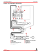
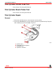
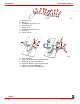
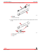
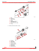
1. If equipped, ensure that the Trim-In Limit Insert is positioned as shown for the appropri-
ate Bravo model.
75157
75158
a
a
Bravo One and Two (Positioned Forward) Bravo Three (Positioned Aft)
a-Trim-In Limit Insert
IMPORTANT: The position of the Trim-In Limit Insert on the Bravo Three sterndrive
unit should only be changed after the boat has been properly tested. Contact the boat
manufacturer if you are not sure of the original position for a particular boat applica-
tion.
INDEX