The following are registered trademarks of Brunswick Corporation: Merc, MerCathode, MerCruiser, Mercury, Mercury Marine, Quicksilver, and Ride-Guide. INSTALLATION MANUAL D7.3L D-TRONIC DIESEL ENGINES - BRAVO MODELS NOTICE to INSTALLER After Completing Installation, These Instructions Should Be Placed with the Product for the Owner’s Future Use. NOTICE to COMMISSIONING DEALER Predelivery Preparation Instructions Must be Performed Before Delivering Boat To The Product Owner.
D7.3L D-TRONIC DIESEL ENGINES - BRAVO MODELS General Information Notice to Installer Throughout this publication, “Warnings” and “Cautions” (accompanied by the International Hazard Symbol ! ) are used to alert the installer to special instructions concerning a particular service or operation that may be hazardous if performed incorrectly or carelessly. –– Observe Them Carefully! These “Safety Alerts,” alone, cannot eliminate the hazards that they signal.
D7.3L D-TRONIC DIESEL ENGINES - BRAVO MODELS WARNING Electrical system components on this engine are not external ignition protected. DO NOT STORE OR UTILIZE GASOLINE ON BOATS EQUIPPED WITH THESE ENGINES, UNLESS PROVISIONS HAVE BEEN MADE TO EXCLUDE GASOLINE VAPORS FROM ENGINE COMPARTMENT (REF: 33 CFR). Failure to comply could result in fire, explosion and/or severe personal injury. Notice on Bravo Trim-In Limit NOTE: Bravo One, Two and Three Models are equipped with a Trim-In Limit Pin Insert.
D7.3L D-TRONIC DIESEL ENGINES - BRAVO MODELS Multiple Sterndrive Steering Tie Bar Arrangements With multiple sterndrives it is important to consider which of several possible steering systems should be selected. CAUTION Failure to observe the recommended Tie Bar Arrangements as presented in this section could result in serious damage to the steering and/or trim system components. This damage could adversely affect control of the boat.
D7.3L D-TRONIC DIESEL ENGINES - BRAVO MODELS Quicksilver Products ACCESSORIES Quicksilver remote controls, steering systems, propellers, etc. are available for this product. Refer to “Quicksilver Accessories Guide” for complete listing. This “Guide” is available from: Attn: Parts Department Mercury Marine W6250 W. Pioneer Road P.O. Box 1939 Fond du Lac, WI 54936-1939 OR – Outside of U.S.A., order through Distribution Center, or Distributor.
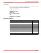
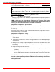
D7.3L D-TRONIC DIESEL ENGINES - BRAVO MODELS Torque Specifications TORQUE DESCRIPTION lb-in. Speedometer Pickup Barb Fitting lb-ft 10-15 Nm 1.2-1.
D7.3L D-TRONIC DIESEL ENGINES - BRAVO MODELS Antifouling Paint IMPORTANT: Corrosion damage that results from the improper application of antifouling paint will not be covered by the limited warranty. Painting Boat Hull or Boat Transom: Antifouling paint may be applied to boat hull and boat transom but you must observe the following precautions: IMPORTANT: DO NOT paint anodes or MerCathode System reference electrode and anode, as this will render them ineffective as galvanic corrosion inhibitors.
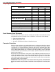
D7.3L D-TRONIC DIESEL ENGINES - BRAVO MODELS Installation Requirements Boat Construction TRANSOM a f e c e 22033 b d 22170 a - Transom Thickness - 2 in. (51mm) Minimum to 2-1/4 in.(57mm) Maximum b - Inner Surface of Transom Must Be Parallel Within 1/8 in. (3mm) in Area Covered by Transom Plate (e) and Remain Within Transom Thickness Limits. c - Outer Surface of Transom Must Be Parallel Within 1/16 in. (2 mm) in Area Covered by Transom Plate (e) and Remain Within Transom Thickness Limits.
D7.3L D-TRONIC DIESEL ENGINES - BRAVO MODELS ENGINE COMPARTMENT WARNING Boating standards (NMMA, ABYC, etc.) and Coast Guard regulations must be adhered to when constructing the engine compartment. Care must be exercised in the design and construction of the engine compartment. Seams must be located so that any rain water, which may leak through the seams, is directed away from the air intake system.
D7.3L D-TRONIC DIESEL ENGINES - BRAVO MODELS Multiplying the engine air flow (cfm) by 0.1 will generally determine the combustion air vent size requirement (per engine). Therefore: Engine Combustion Air Flow (cfm) X 0.1 OR Engine Combustion Air Flow (m3/min.) X 22.8 D7.3 D-Tronic Example: OR 1 = Combustion Air Vent Area Per Engine (Square Inches) = Combustion Air Vent Area Per Engine (Square Centimeters) 1000 X 0.1 = 100 Square Inches1 28.2 X 22.8 = 642.9 Sq. Cm.
D7.3L D-TRONIC DIESEL ENGINES - BRAVO MODELS Exhaust System IMPORTANT: It is the responsibility of the boat manufacturer or installing dealer to properly locate the engine and install the exhaust system. Improper installation may allow water to enter the exhaust manifolds and combustion chambers and severely damage the engine. Damage caused by water in the engine will not be covered by MerCruiser Warranty, unless this damage is the result of defective part(s).
D7.3L D-TRONIC DIESEL ENGINES - BRAVO MODELS Some engines may be equipped with a factory installed exhaust riser. Verify that the riser provides the required dimension “c”, or a distance greater than “c”, as indicated. Model All Models (c) = (a) Minus (b) (c) Must Be 13 in.
D7.3L D-TRONIC DIESEL ENGINES - BRAVO MODELS 4. The tank breather pipe must have an inner diameter of at least 1/2 in. (13mm) and must be fitted with a swan neck to prevent water from entering the tank. It is recommended that the exact route and length of the fuel lines be established at the first installation of the engine to prevent problems later in connecting them to the engine. All fuel lines must be well secured.
D7.3L D-TRONIC DIESEL ENGINES - BRAVO MODELS Battery IMPORTANT: Boating industry standards (BIA, ABYC, etc.) federal standards and Coast Guard regulations must be adhered to when installing battery. Be sure battery cable installation meets the pull test requirements and that positive battery terminal is properly insulated in accordance with regulations. IMPORTANT: It is recommended (required in some states) that battery be installed in an enclosed case. Refer to regulations for your area.
D7.3L D-TRONIC DIESEL ENGINES - BRAVO MODELS EDI Electrical System Precautions NOTE: The following precautions apply to all EDI model Engines. CAUTION Avoid damage to the Electronic Direct Injection (EDI) electrical system and components. Refer to the following precautions when working on or around the EDI electrical harness or when adding other electrical accessories: • DO NOT tap accessories into engine harness. • DO NOT puncture wires for testing (Probing). • DO NOT reverse battery leads.
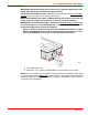
D7.3L D-TRONIC DIESEL ENGINES - BRAVO MODELS c b a 76010 D7.3L D-Tronic Shown - All Similar a - Engine Harness Connector b - Extension Harness Connector (From Instruments) c - Electrical Bracket TACHOMETER SPECIAL INFORMATION IMPORTANT: If using a tachometer from another manufacturer, do not use the magnetic tachometer pickup (or related wiring) mounted on the flywheel housing.
D7.3L D-TRONIC DIESEL ENGINES - BRAVO MODELS Propeller Selection GENERAL INFORMATION IMPORTANT: Installed propeller must allow engine to run at its specified maximum wide-open-throttle revolutions per minute (rpm). Use an accurate service tachometer to verify engine operating rpm. It is the responsibility of the boat manufacturer and/or the selling dealer to equip the power package with the correct propeller(s).
D7.3L D-TRONIC DIESEL ENGINES - BRAVO MODELS Hot Water Heater Installation Recommendation IMPORTANT: When connecting a cabin heater or hot water heater, certain requirements must be met, including, but not limited to the following: • Supply hose (from engine to heater) and return hose (from heater to engine) MUST NOT EXCEED 5/8 in. (16 mm) I.D. (inside diameter). • Make heater connections ONLY at locations indicated in the following information.
D7.3L D-TRONIC DIESEL ENGINES - BRAVO MODELS RETURN HOSE CONNECTION a 76023 a - Location on Water Circulation Pump for Hot Water Return (Bayonet Fitting Replaces Plug) Seawater Connections D7.3L D-Tronic and D7.3L D-Tronic LD models must be equipped with a through hull or through transom water supply to ensure sufficient water flow to the engine. The transom assembly needs to be modified with the water passage block-off plate kit (P/N 818304A1) provided.
D7.3L D-TRONIC DIESEL ENGINES - BRAVO MODELS SEAWATER STRAINER Strainer used must be of sufficient size to ensure that an adequate supply of water will be maintained for cooling the engine. Seawater Strainer Minimum Flow Rate 1 All Models 1 Amount 40 (150) listed is in gallons per minute and (liters per minute). Install seawater strainer in an area where it will be easily accessible for inspection and cleaning.
D7.3L D-TRONIC DIESEL ENGINES - BRAVO MODELS Steering Helm and Cable Transom assembly is shipped with the steering cable guide tube preset for cables with end dimensions that comply with ABYC standards as outlined in the NMMA certification handbook. The steering cable coupler nut must also have a means of locking it to the guide tube as specified in ABYC requirements. WARNING Failure to use a steering cable locking device could cause loss of steering, which could cause damage to the boat and/or injury.
D7.3L D-TRONIC DIESEL ENGINES - BRAVO MODELS CAUTION POWER STEERING EQUIPPED UNITS ONLY: If steering cable with improper dimensions is installed, severe damage to transom assembly and/or steering system may result. 1. Steering cable must be the correct length, particularly when installed in larger boats. 2. Avoid sharp bends, kinks or loops in cable. 3. Fully extended steering cable end dimension must be as shown.
D7.3L D-TRONIC DIESEL ENGINES - BRAVO MODELS Transom Cutout NOTICE to INSTALLER Before Starting Installation Read “General Information” and “Installation Requirements” Sections Completely. IMPORTANT: The following instructions will provide a sterndrive unit mounting location that is suitable for most boats. Best mounting location for a particular boat, however, can be determined only by testing. Bravo Models use items 1 - 4. 1. Below 25 m.p.h. (40 km/h): Subtract 1/2 in. (13mm) from “X” Dimension Shown. 2.
D7.3L D-TRONIC DIESEL ENGINES - BRAVO MODELS Finding Crankshaft Vertical Centerline SINGLE ENGINE Locate and mark vertical centerline on transom. a 71620 a - Vertical Centerline DUAL ENGINE 1. Locate and mark boat vertical centerline (a) on transom. a 71620 a - Vertical Centerline 2. Locate and mark crankshaft vertical centerlines (a) on transom.
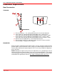
D7.3L D-TRONIC DIESEL ENGINES - BRAVO MODELS Finding Crankshaft Horizontal Centerline (“X” Dimension) “X” Dimension can be measured by the “90° Tool Method” or by the “Tape Measure Method.” 90° TOOL METHOD 1. Construct 90° tool. a 90° b 71621 a - Dimension from Chart Below b - Measurement: 4 ft. (1.2 m) To Lower Drive Unit - Subtract from dimension “a”. To Raise Drive Unit - Add to dimension “a”. 90° TOOL VERTICAL DIMENSION CHART Sterndrive Unit Location Bravo One/Two/Three 13-9/16 in.
D7.3L D-TRONIC DIESEL ENGINES - BRAVO MODELS TAPE MEASURE METHOD Transom angle must be known, then measure “X” Dimension with tape measure. 1. Determine “X” Dimension from the following chart. Tape Measure Method Chart Model Bravo One / Two / Three Transom Angle This dimension should only be raised or lowered after proper testing. 16° 14-5/16 in. (364 mm) 15° 14-1/4 in. (362 mm) 14° 14-3/16 in. (360 mm) 13° 14-1/8 in. (359 mm) 12° 14-1/16 in. (357 mm) 11° 14 in.
D7.3L D-TRONIC DIESEL ENGINES - BRAVO MODELS Cutting Transom Transom cutout can be made by either using the Template [shipped with transom assembly] or the Transom Drilling Fixture Kit (purchased separately). Follow instructions indicated on template or provided with drilling fixture. IMPORTANT: Read and observe the following information: • Be certain that centerlines on either the template or transom drilling fixture align with lines previously marked on transom. • Be sure to drill 1/4 in.
D7.3L D-TRONIC DIESEL ENGINES - BRAVO MODELS Checking Transom Thickness Ensure transom surface thickness and flatness conform to minimums specified in “Installation Requirements” listed previously. NOTE: Transom must be between 2” (51 mm) and 2-1/4” (57 mm) a distance of 8” (203 mm) to either side of the vertical centerline. a b c a - Measuring Thickness b - Measuring Flatness c - Suitable Mandrel To Check For Uniform Transom Thickness.
D7.3L D-TRONIC DIESEL ENGINES - BRAVO MODELS Installing Transom Assembly Gimbal Housing 1. Carefully remove transom assembly from shipping carton. 2. Remove and read all tags which are attached to transom assembly. IMPORTANT: Read and observe the following regarding your engine and the thrupropeller exhaust system: • With any application, installation of an exhaust tube will increase exhaust noise.
D7.3L D-TRONIC DIESEL ENGINES - BRAVO MODELS Inner Transom Plate 1. Insert wires, hoses and shift cable through appropriate openings in inner transom plate. 2. Position gimbal housing on transom and hold in place. NOTE: When tightening transom assembly fasteners in the following step, start in the center and, using a circular pattern, move outward. Tighten in small increments and go around the pattern several times until the proper torque is achieved.
D7.3L D-TRONIC DIESEL ENGINES - BRAVO MODELS Power Trim Pump 1. Mount pump in desired location. IMPORTANT: Make hydraulic connections as quickly as possible to prevent oil from leaking out of system. Be careful not to cross-thread or overtighten hose fittings.
D7.3L D-TRONIC DIESEL ENGINES - BRAVO MODELS Steering System NOTE: For Dual Installations, Power steering unit can be mounted on port or starboard transom assembly. Measure exact distance between power package centerlines. Select a tie bar from Quicksilver Accessory Guide. Refer to tie bar installation instructions before proceeding. 1. Inspect bushings for debris. Lubricate bushings with Special Lubricant 101. B a 73898 a - Bushings b - Special Lubricant 101 2.
D7.3L D-TRONIC DIESEL ENGINES - BRAVO MODELS 4. Torque pivot bolts to 25 lb-ft (34 Nm). Bend washer tabs against corresponding flats on bolt heads. CAUTION MOVING THE CONTROL VALVE RAM with the hoses disconnected will expel fluid from the ports. Wear eye protection. 5. The cylinder ram may be stiff and difficult to move when you attempt to pull it out or push it in for installation. First move the spool assembly in the direction(s) shown below. a 74145 a 74144 a - Ports 6.
D7.3L D-TRONIC DIESEL ENGINES - BRAVO MODELS 7. Connect steering cable as follows: a. Remove shipping cap from both ends of steering cable guide tube. b. Coat steering cable end with a liberal amount of Special Lubricant 101. c. Install steering cable and secure with hardware as shown.
D7.3L D-TRONIC DIESEL ENGINES - BRAVO MODELS Speedometer Pickup IMPORTANT: Do not disturb plug at speedometer fitting if no speedometer is to be fitted, or if an alternate speedometer pickup will be used. 1. Remove plug from speedometer pickup tube fitting. a b 70037 a - Fitting Plug b - Speedometer Pickup Tube Fitting 2. Apply Perfect Seal to threads of barb fitting. Install and torque to 10-15 Ib. in. (1.1-1.7 N⋅m). a 70015 a - Barb Fitting 3. Connect hose from speedometer to barb fitting.
D7.3L D-TRONIC DIESEL ENGINES - BRAVO MODELS 3. Route hose to monitor bottle mounted on engine and cut off excess hose. IMPORTANT: Avoid using excessive hose when routing to gear lube monitor. Hose should be routed directly, in as straight a line as possible, to avoid low spots (traps) in the system.
D7.3L D-TRONIC DIESEL ENGINES - BRAVO MODELS Drive Unit Seawater Routing Seawater for engine cooling is supplied through a separate seawater pickup, not through the drive unit. Therefore, it is necessary to block the drive unit seawater passage and to cut the water hose that is located between the bell housing and the gimbal housing. This allows water to continue to circulate through the drive unit for cooling. BLOCK-OFF PLATE 1. Install block-off plate with gasket.
D7.3L D-TRONIC DIESEL ENGINES - BRAVO MODELS SEAWATER HOSE NOTE: The trim limit switch wires and speedometer hose are attached to the water hose. Prior to cutting the hose, move the wires and speedometer hose to avoid cutting them when cutting water hose. The existing sta-strap and clip can be reused if they are moved out of the way while cutting the water hose. 1. Move existing sta-strap and clip. Cut the water hose in the area shown.
D7.3L D-TRONIC DIESEL ENGINES - BRAVO MODELS Engine Installation Engine Preparation 1. Remove and read all tags attached to engine. 2. Remove all hardware that secures engine to shipping container. 3. Loosen fasteners and remove exhaust pipe and exhaust hose from pallet. 4. Connect battery cables to engine. Be sure to observe the following: a. Make sure that grounding stud and starter solenoid terminal are free of paint or any other material that could cause a poor electrical connection. b.
D7.3L D-TRONIC DIESEL ENGINES - BRAVO MODELS Transom Preparation IMPORTANT: Exhaust pipe and gimbal housing mating surfaces must be clean and free of nicks and scratches, and O-ring must be properly seated in groove, or water and exhaust may leak into boat. a b 22059 a - Gimbal Housing Mating Surface b - O-ring 1. Install exhaust pipe assembly as shown, using four (4) bolts and thick lockwashers. Torque bolts to 20-25 lb-ft (27-34 Nm). 2.
D7.3L D-TRONIC DIESEL ENGINES - BRAVO MODELS Installing Engine / Alignment 1. Attach a suitable sling to lifting eyes on engine and adjust so that engine is level when suspended. 2. Lift engine into position (in boat), using an overhead hoist. CAUTION When lowering engine into position DO NOT set engine on shift cable. Shift cable outer casing can be crushed causing difficult or improper shifting.
D7.3L D-TRONIC DIESEL ENGINES - BRAVO MODELS 3. Align rear engine mounts with inner transom plate mounts. Set engine onto front mounts and inner transom plate mounts, while simultaneously aligning exhaust elbow with exhaust tube. (Do not relieve hoist tension.)nd IMPORTANT: Engine attaching hardware must be installed in sequence shown. 4. Install both rear engine mounting bolts and hardware as shown. Torque to 35-40 lb-ft (47-54 Nm).
D7.3L D-TRONIC DIESEL ENGINES - BRAVO MODELS 7. Attach chain and hooks from suitable engine sling to starboard front lifting eye and port mounted Engine Lifting Eye Tool. Attach a suitable hoist to this sling. NOTE: Installing sling between specified lifting eyes will help equalize load on hoist during alignment procedure. b a 76012 71961 a - Engine Sling In Starboard Lifting Eye b - Engine Sling In Port Mounted Engine Lifting Eye Tool 8. Align engine as follows: a.
D7.3L D-TRONIC DIESEL ENGINES - BRAVO MODELS CAUTION DO NOT use an alignment tool from another manufacturer. Alignment tools other than Quicksilver Alignment Tool may cause improper alignment and damage to gimbal bearing and/or engine coupler. CAUTION To avoid damage to gimbal bearing, engine coupler, or alignment tool: DO NOT attempt to force alignment tool! DO NOT raise or lower engine with alignment tool inserted (or partially inserted) in gimbal bearing or engine coupler. b.
D7.3L D-TRONIC DIESEL ENGINES - BRAVO MODELS IMPORTANT: Finished boat stringer must position engine so that a minimum mount adjustment exists after front mount is adjusted down to stringer. This allows for future adjustments. 9. Adjust front mount assembly until it touches stringer. 10. Recheck alignment with alignment tool. Tool must enter coupler splines freely. If not, readjust front mounts. 11. When alignment is correct, tighten locknut or nut with lockwasher on each mount securely. 12.
D7.3L D-TRONIC DIESEL ENGINES - BRAVO MODELS Engine Connections Quicksilver Seawater Pickup and Seacock 1. Drill a 2 in. (50mm) hole thru hull in appropriate location (Refer to “Installation Requirements.”). 2. Apply marine caulking (sealer) to mounting surface on seawater pickup (thru-hull fitting) where hull contact will occur when installed. 3. Ensure slots in water pickup are facing forward and install water pickup. Position washer on fitting and install large nut. Tighten nut securely.
D7.3L D-TRONIC DIESEL ENGINES - BRAVO MODELS Seawater Strainer When using a seawater strainer other than Quicksilver Seawater Filter (Part Number 35-801763739) refer to manufacturer’s instructions for installation, operation and maintenance. Refer to the following when installing and connecting Quicksilver seawater strainer. IMPORTANT: Read and observe the following: Mount the seawater strainer in a vibration free location. Never mount the seawater strainer on the engine.
D7.3L D-TRONIC DIESEL ENGINES - BRAVO MODELS Closed Cooling Recovery Bottle 1. Connect plastic tubing (from kit) to bayonet fitting on heat exchanger. Secure with tubing clamp provided. 2. Select a mounting location for coolant recovery bottle and mounting bracket that meets all of the following: a. Within limits of clear plastic tubing. b. Below horizontal level of heat exchanger fill neck. c. Accessible for observing coolant level and filling. 3.
D7.3L D-TRONIC DIESEL ENGINES - BRAVO MODELS Fuel Lines 1. Connect flexible fuel line to fuel supply fitting. Secure with hose clamp. 2. Connect flexible fuel line to fuel return fitting. Secure with hose clamp. b a 76027 a - Fuel Supply Fitting b - Fuel Return Fitting Power Steering Hydraulic Hoses CAUTION Route hoses exactly as shown below. This will help avoid stress on the hose fittings and will help avoid kinks in the hose. 1. Connect power steering hoses to control valve. Position hoses as shown.
D7.3L D-TRONIC DIESEL ENGINES - BRAVO MODELS Exhaust System 1. Tighten exhaust tube hose clamps securely. c a d b 76106 Typical a - Elbow b - Tube c - Hose Clamps (4) d - Pipe Electrical Connections CONTINUITY CIRCUIT 1. Connect continuity circuit wire (supplied with engine package) from engine to transom assembly. Tighten inner transom plate screw securely.
D7.3L D-TRONIC DIESEL ENGINES - BRAVO MODELS INSTRUMENTS AND EXTENSION HARNESSES NOTE: If using other than Quicksilver instrumentation and harnesses, refer to manufacturers’ instructions. 1. Follow the appropriate instructions “a”, “b” and/or “c”, depending upon boat configuration: a. Prepare dash openings and/or mount gauges according to instructions provided with individual gauges. b.
D7.3L D-TRONIC DIESEL ENGINES - BRAVO MODELS 3. Refer to Quicksilver Instrumentation Wiring Diagram. Using screws provided, connect the listed color coded wires to numbered switch terminals as shown. D7.3L D-Tronic Harness Wire (Color Code) Connect To: 16C BLACK (BLK) 40A YELLOW (YEL) LT1 BLUE (BLU) 12C PURPLE (PPL) Terminal Number 2 1 5 4 4. Make sure that all instrument and switch connections are secure. Seal terminals with Liquid Neoprene (92-25711). 5.
D7.3L D-TRONIC DIESEL ENGINES - BRAVO MODELS NEUTRAL SAFETY SWITCH CONNECTION 1. Connect neutral safety switch wires at instrument panel and remote control. Refer to appropriate wiring diagram. Secure connections as shown and coat with Liquid Neoprene. Slide rubber sleeve over connections. c a b RED 36BC2 YEL/RED PUR 36BC d c PUR 36BC3 YEL/RED a b c d PUR 36BC1 a - Instrument Harness Wires - Two Wire Connector - To Remote Control - Rubber Sleeves TRIM POSITION SENDER CONNECTION 1.
D7.3L D-TRONIC DIESEL ENGINES - BRAVO MODELS Shift Cable Installation and Adjustment NOTE: Shift Cable Adjustment Tool (91-12427) allows the shift cables to be installed and adjusted, with or without the sterndrive attached. IMPORTANT: The direction of propeller rotation (RH or LH) for this drive unit is determined by the following method. 1. Determine desired propeller rotation according to “a”, “b”, or “c”: a.
D7.3L D-TRONIC DIESEL ENGINES - BRAVO MODELS 4. Install drive unit shift cable. a b c 23345 a - Washers (2) b - Lock Nut - Tighten Until Contact, Then Back Off 1/2 Turn c - Cotter Pin - Insert from Top and Spread Both Ends 5. Place adjustment tool over drive unit shift cable, as shown. Hold tool in place, using a piece of tape over the barrel retainer. 23242 6. Locate center of remote control and control cable play (backlash). a. Shift remote control to neutral. b.
D7.3L D-TRONIC DIESEL ENGINES - BRAVO MODELS 7. Adjust remote control shift cable as follows: a. Temporarily install shift cable end guide into shift lever, and insert anchor pin. b. Adjust shift cable barrel so that hole in barrel centers with vertical centerline of stud. Ensure that backlash center mark is aligned with edge of control cable end guide.
D7.3L D-TRONIC DIESEL ENGINES - BRAVO MODELS 10. Shift remote control lever into full forward position. Place end of adjustment tool in barrel retainer. RH ROTATION BRAVO ONE, TWO, THREE AND BLACKHAWK MODEL: Rear slot in tool should fit over shift lever stud. LH ROTATION BRAVO ONE AND TWO: Forward slot in tool should fit over shift lever stud. If slot does not fit over stud, loosen shift lever stud and slide stud either direction, until slot in tool fits over stud.
D7.3L D-TRONIC DIESEL ENGINES - BRAVO MODELS Troubleshooting Shift Problems NOTE: The following information is provided to assist an installer in troubleshooting if hard shifting or chucking/racheting is encountered when shifting into forward gear. 1. When installing the control box in the side panel of the boat, make sure that the cables have enough clearance to operate. This is necessary because the cables move up and down when the shift handle is moved.
D7.3L D-TRONIC DIESEL ENGINES - BRAVO MODELS 4. Do not strap or clamp the control cables to any other cables or rigid structure within three feet of the control box. 5. Be sure the cable is not permanently kinked. 6. Make sure there is proper clearance for cable movement when the control box is installed in the side panel. The cables must have room to move up and down when the control handle is shifted into either forward or reverse. 7.
D7.3L D-TRONIC DIESEL ENGINES - BRAVO MODELS Throttle Cable Installation and Adjustment IMPORTANT: When installing throttle cables, be sure that cables are routed in such a way as to avoid sharp bends and/or avoid contact with moving parts. DO NOT fasten any items to throttle cables. 1. Place remote control lever(s) in neutral/idle position. 2. Measure between the center of the Accelerator Position Sensor anchor stud to the holes on the cable barrel end bracket.
D7.3L D-TRONIC DIESEL ENGINES - BRAVO MODELS c b a d 76025 Single Cable Shown (Dual Similar) a - Accelerator Position Sensor (APS/IVS) b - APS/IVS Anchor Stud c - Cable Barrel End Bracket d - Cable Barrel Anchor Stud c a c b d d e e a - Throttle Cable End Guide b - Cable Barrel c - Anchor Stud d - Flat Washer and Locknut e - Spacer - With Dual Cables f - Cable Barrel Locations - With Dual Cables 4. Tighten locknuts until they bottom and back off 1/2 turn. 5.
D7.3L D-TRONIC DIESEL ENGINES - BRAVO MODELS Sterndrive Unit Installation 1. Remove trim cylinders’ support and dust cover from bell housing studs. Retain locknuts and flat washers. 2. Remove cap and fill gear lube monitor. b a 75955 a - Gear Lube Monitor b - Cap 3. Push in on dribble valve until gear lube appears. a 72471 a - Dribble Valve 4. Once gear lube appears, release dribble valve. 5. Fill monitor to FILL mark. 6. Replace monitor cap.
D7.3L D-TRONIC DIESEL ENGINES - BRAVO MODELS 7. Coat studs with 2-4-C Marine Lubricant with Teflon. a 72471 a - Studs (6) 8. Lubricate U-joint shaft splines and U-joint shaft O-rings with Engine Coupler Spline Grease.
D7.3L D-TRONIC DIESEL ENGINES - BRAVO MODELS 9. Check drive shaft bellows for cleanliness and absence of debris. a 72472 a - Driveshaft Bellows 10. Lubricate O-ring seals with 2-4-C Marine Lubricant with Teflon. a 72183 a - O-Ring Seals 11. Pull out shift linkage as far as it moves. “Jaws” will open, as shown.
D7.3L D-TRONIC DIESEL ENGINES - BRAVO MODELS 12. Place Remote Control in neutral position. NOTE: As bell housing shift cable enters the shift linkage assembly, it pushes the assembly back into the sterndrive housing, and the “jaw” closes, securing the cable, as shown in steps “A”, “B” and “C”. A B C 72467 IMPORTANT: If Bell Housing Shift Cable (b) does not line up to properly enter “jaws” of shift linkage assembly (a), cable will have to be aligned manually.
D7.3L D-TRONIC DIESEL ENGINES - BRAVO MODELS 14. Secure drive unit to bell housing with 5 flat washers and 6 locknuts. Torque to 50 Ib. ft. (68 N⋅m). b a 71244 a - Do Not Install Flat Washer Here b - Elastic Stop Nuts (6) and Flat Washers (5) IMPORTANT: On Bravo One, Two and Three Models, the “Trim-In Limit Pin Insert” must be properly positioned before installing the trim cylinder anchor pin in the following steps. 15.
D7.3L D-TRONIC DIESEL ENGINES - BRAVO MODELS IMPORTANT: The position of the Trim-In Limit Pin on the Bravo Three sterndrive unit should only be changed after the boat has been properly tested. Refer to statement at the front of this manual entitled; “Bravo Three Notice: Trim-In Limit Pin”. IMPORTANT: To aid in installing rubber bushings, use a water and soap solution. DO NOT use oil or grease. 16. Install trim cylinders on aft end of drive unit with hardware as shown.
D7.3L D-TRONIC DIESEL ENGINES - BRAVO MODELS 18. On All Drive Units - Perform steps 19 through 21. 19. Raise drive to gain access to area between gimbal housing and sterndrive, immediately atop the transom end of the anti-ventilation plate. 20. Insert speedometer tube fitting into opening on topside of anti-ventilation plate, in position shown. a b 22025 a - Tube Fitting b - Opening 21. With fitting fully seated, turn handle to left to a tightly seated position, as shown.
D7.3L D-TRONIC DIESEL ENGINES - BRAVO MODELS Predelivery Preparation NOTICE Before starting Predelivery read “General Information” and “Installation Requirements” completely. Battery Connection IMPORTANT: Engine electrical system is negative (–) ground. 1. Connect engine positive (+) battery cable (usually RED) to positive (+) battery terminal. 2. Connect engine negative (–) battery cable (usually BLACK) to negative (–) battery terminal. 3.
D7.3L D-TRONIC DIESEL ENGINES - BRAVO MODELS a 22031 a - Fill Neck 3. Check all trim line connection points for leaks. If fluid is visible at fittings, tighten fitting(s). Torque fitting(s) to 100-150 lb-in. (11-16 Nm). Trim Position Sender Adjustment 1. Loosen both trim position sender attaching screws. b a 71220 a - Attaching Screws b - Trim Position Sender CAUTION DO NOT start engine in the following step or damage to drive unit and engine could result from lack of cooling water. 2.
D7.3L D-TRONIC DIESEL ENGINES - BRAVO MODELS 4. Rotate trim position sender as required to show full DOWN/IN position on dashboard instrument as shown. a 71671 a - Trim Gauge Needle 5. Tighten retaining screws and turn ignition key to the “OFF” position.
D7.3L D-TRONIC DIESEL ENGINES - BRAVO MODELS Power Steering Fluid IMPORTANT: Use only Quicksilver Power Trim and Steering Fluid, or Dexron III automatic transmission fluid (ATF), in power steering system. CAUTION DO NOT RUN POWER STEERING DRY, or pump will be damaged. 1. Position drive unit so that it is straight back. 2. Remove fill cap from power steering fluid reservoir, and check fluid level. Fill to “FULL COLD” line – do not over fill.
D7.3L D-TRONIC DIESEL ENGINES - BRAVO MODELS 1. With drive in full down position, remove oil vent screw. CAUTION Failure to fill drive unit to level of vent hole will result in a low drive oil level. Gear lube monitor only MAINTAINS drive oil level and will not correct an improperly filled drive unit. 2. Fill gear lube monitor with Quicksilver Gear Lube. When oil starts to run out the oil vent hole, reinsert oil vent screw, and sealing washer, and tighten securely. 3. Fill monitor to “FILL” mark.
D7.3L D-TRONIC DIESEL ENGINES - BRAVO MODELS 2. Install propeller with attaching hardware as shown. Tighten nut a minimum of 55 lb-ft (75 Nm), then continue to tighten until 3 tabs on the tab washer align with grooves on spline washer. Bend the 3 tabs down into grooves.
D7.3L D-TRONIC DIESEL ENGINES - BRAVO MODELS BRAVO THREE IMPORTANT: Correct rotation propeller MUST match direction of rotation of propeller shaft. WARNING Be sure that remote control is in neutral position and ignition key is removed from switch prior to installing propeller. WARNING Place a block of wood between the anti-ventilation plate and propeller to protect hands from propeller blades and to prevent propeller from turning when tightening propeller nut. 1.
D7.3L D-TRONIC DIESEL ENGINES - BRAVO MODELS Test Running Engine WARNING Electrical system components on this engine are not external ignition protected. DO NOT STORE OR UTILIZE GASOLINE ON BOATS EQUIPPED WITH THESE ENGINES, UNLESS PROVISIONS HAVE BEEN MADE TO EXCLUDE GASOLINE VAPORS FROM ENGINE COMPARTMENT (REF: 33 CFR). Failure to comply could result in fire, explosion and/or severe personal injury. WARNING If engine is to be tested with boat out of water, the propeller must be removed to avoid injury.
D7.3L D-TRONIC DIESEL ENGINES - BRAVO MODELS 8. Refer to “Operation and Maintenance Manual” and start engine. Run at idle rpm until water temperature is normal. 9. Watch all gauges for normal readings. 10. Turn steering wheel starboard, then port, and check to ensure drive unit turns the correct way. 11. Inspect engine compartment for water, oil, fuel and exhaust leaks. 12. Check for lugging condition. a. Turn steering wheel left until it stops, and continue to apply pressure.
D7.3L D-TRONIC DIESEL ENGINES - BRAVO MODELS 14. Restart engine and observe drive unit. If drive unit creeps, an external tension may exist on steering cable. Ensure that there is nothing attached to steering cable casing. Cable must be free to move when actuated. 15. Check power steering pump fluid level: a. Position drive unit so it is straight back. Turn off engine. b. Remove cap/dipstick from power steering fluid reservoir. Check fluid level and add as necessary. Do not overfill.
D7.3L D-TRONIC DIESEL ENGINES - BRAVO MODELS Boat-In-The-Water Tests IMPORTANT: Engine alignment MUST BE CHECKED with boat in the water, fuel tanks filled, and with a normal load onboard. IMPORTANT: DO NOT perform the following with boat in a test tank or tied to dock. ENGINE INITIAL BREAK-IN PROCEDURE It is especially important that the following procedure be used on new diesel engines.
D7.3L D-TRONIC DIESEL ENGINES - BRAVO MODELS IMPORTANT: To run engine at maximum rpm before the Engine 20-Hour Break-In Period is complete, follow this procedure only after the Engine Initial Break-in Procedure has been completed: 1. Complete Engine Initial Break-In Procedures if not already accomplished. 2. Start engine and run at idle rpm until normal operating temperature is reached. 3. Run boat up on plane. 4. Advance engine rpm (in 200 rpm increments) until engine reaches its maximum rated rpm.
D7.3L D-TRONIC DIESEL ENGINES - BRAVO MODELS Cold Weather or Extended Storage Draining Instructions CAUTION If Power Package will not be used for an extended period of time or will be exposed to freezing temperatures, drain water from seawater section of cooling system. Water MUST BE drained to prevent corrosion and freeze damage to engine.
D7.3L D-TRONIC DIESEL ENGINES - BRAVO MODELS 1. Close seacock, if so equipped, or disconnect and plug seawater inlet hose, if boat is to remain in the water. 2. Remove and drain the following: a. The end covers from both the port and starboard sides of heat exchanger. Drain tank completely. IMPORTANT: Use compressed air to blow any remaining water from the tubes in the heat exchanger. b. The drain plug on the lower side of the engine oil cooler. c.
D7.3L D-TRONIC DIESEL ENGINES - BRAVO MODELS 3. Repeatedly clean out drain holes using a stiff piece of wire. Do this until entire system is drained. 4. Remove seawater pump outlet hose from top of seawater pump and drain. b a 76107 a - Seawater Pump b - Outlet Hose CAUTION Avoid water entering boat. Do not unplug or disconnect seawater inlet hose unless a seacock is present and it is closed. 5. Remove hose(s) at seawater strainer and drain hose(s) completely.
D7.
D7.
D7.
D7.
D7.
D7.
D7.