
Automobile Parts User Manual

D7.3L D-TRONIC DIESEL ENGINES - BRAVO MODELS
Page 51 of 90
INSTRUMENTS AND EXTENSION HARNESSES
NOTE: If using other than Quicksilver instrumentation and harnesses, refer to manufactur-
ers’ instructions.
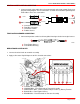
1. Follow the appropriate instructions “a”, “b” and/or “c”, depending upon boat configura-
tion:
a. Prepare dash openings and/or mount gauges according to instructions provided
with individual gauges.
b. Prepare dash opening and/or mount Engine System Monitor Panel to dashboard fol-
lowing Instruction Sheet/Template 90-806330.
c. Extend wires through dash openings and/or connect all instrument wiring harness
leads to the individual gauges and Engine System Monitor Panel. Refer to Quicksil-
ver Instrumentation Wiring Diagram, wire identification tags and instructions pro-
vided with individual gauges and kits.
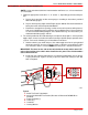
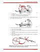
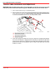
2. The switch provided for the audio warning test and panel (dash) lights is a three-position
toggle switch. It must be wired and installed correctly to provide proper operation of the
systems. Refer to the following special installation instructions:
a. Hold the switch in your hand and press the switch toggle lever into its spring loaded
momentary position. You must install the switch so that the “spring loaded”, Audio
Test end of the switch is oriented DOWN once the panel is installed in the boat.
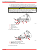
IMPORTANT: The decal on the side of the switch with the arrow and the word “UP”
refer to the position of the switch
when installed on the panel
. The circled numbers
refer to wire terminals.
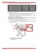
b. Install jamb nut, and then locking washer, on switch threaded portion. Secure to pan-
el using knurled nut. Tighten securely, to prevent switch from turning in hole. DO
NOT overtighten.
71886
73369
87-805675
UP
123
e
UP
a
b
c
f
b
e
a
d
1
2
3
4
5
6
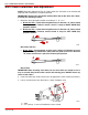
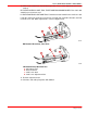
Typical
a-Audio Test/Panel Light Switch
b-Spring-Loaded Audio Test Portion (Direction of Movement DOWN When
Installed)
c-Terminal Number(s)
d-Terminal(s)
e-Jamb Nut
f-Locking Washer