
Automobile Parts User Manual

D7.3L D-TRONIC DIESEL ENGINES - BRAVO MODELS
Page 52 of 90
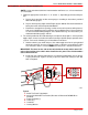
3. Refer to Quicksilver Instrumentation Wiring Diagram. Using screws provided, connect
the listed color coded wires to numbered switch terminals as shown.
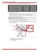
D7.3L D-Tronic
Harness Wire (Color Code) Connect To: Terminal Number
16C BLACK (BLK)
2
40A YELLOW (YEL)
1
LT1 BLUE (BLU)
5
12C PURPLE (PPL)
4
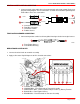
4. Make sure that all instrument and switch connections are secure. Seal terminals with
Liquid Neoprene (92-25711).
5. Mount gauges according to instructions provided with individual gauges. Mount Engine
System Monitor Panel to dashboard following Instruction Sheet/Template.
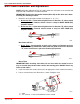
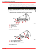
6. Connect instrument extension harnesses to instrument harness ends. Connector
collars must be fully engaged and secure.
IMPORTANT: When routing any wiring extension harness back to the engine, make
sure that the harness does not rub or get pinched.
7. Route instrument extension harnesses back to engine. Fasten harnesses to the boat
at least every 18 in. (460 mm), using appropriate fasteners.
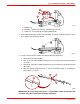
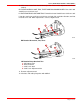
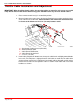
8. Connect extension harness to engine harness end on side of electrical bracket. Tighten
locking connector collar.
75337
76010
a
b
c
a-Extension Harness From Instruments
b-Engine Harness and Connector End
c-Electrical Bracket