Mainboard User’s Manual This publication, photographs, illustrations and software are under the protection of international copyright laws and all rights reserved. It does not allow any reproduction of this manual, content and any materials contained herein without the written consent of the authentic manufacturer. The information in this manual is subject to change without notice.
Mainboard User’s Manual Notice: Owing to Microsoft’s certifying schedule is various to every supplier, we might have some drivers not certified yet by Microsoft. Therefore, it might happen under Windows XP that a dialogue box (shown as below) pop out warning you this software has not passed Windows Logo testing to verify its compatibility with Windows XP. Please rest assured that our RD department has already tested and verified these drivers.
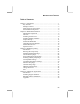
Mainboard User’s Manual Table of Contents Chapter 1: Introduction ...................................................................1 Key Features............................................................................2 Package Contents ....................................................................5 Static Electricity Precautions...................................................6 Pre-Installation Inspection.......................................................
Mainboard User’s Manual IV
1: Introduction Chapter 1 Introduction This mainboard has a Socket-478 support for Intel Pentium4 processors with front-side bus (FSB) speeds up to 400 MHz. This mainboard has the Intel 845GL chipset that contains Intel 82845 Memory Controller Hub and Intel 82801 I/O Controller Hub. It supports built-in USB 2.0 providing higher bandwidth. It implements Universal Serial Bus Specification Revision 2.0 and is compliant with UHCI 1.1 and EHCI 0.95.
Mainboard User’s Manual Key Features This mainboard has these key features: Socket-478 Processor ♦ Supports Intel Pentium 4 series CPUs ♦ Supports up to 400 MHz Front-Side Bus Memory Support ♦ Two 168-pin DIMM slots for SDRAM memory modules ♦ Two 184-pin DIMM slots for DDR SDRAM memory modules ♦ Support SDRAM up to 133 MHz/DDR up to 266 MHz memory bus ♦ Maximum installed memory is 2GB Notice: YOU can NOT work SDRAM and DDR simultaneously. AC97 Audio Codec: CMI9738 ♦ Compliant with AC’97 2.
1: Introduction Onboard I/O Ports The mainboard has a full set of I/O ports and connectors: ♦ Two PS/2 ports for mouse and keyboard ♦ One serial ports ♦ One parallel port ♦ One VGA port ♦ One MIDI/game port ♦ Six USB ports (two back-panel USB ports, onboard USB headers providing maximum four extra ports: header USB2 and USB3)—all support USB 2.
Mainboard User’s Manual BIOS Firmware This mainboard uses AMI BIOS that enables users to configure many system features including the following: ♦ Power management ♦ Wake-up alarms ♦ CPU parameters and memory timing ♦ CPU and memory timing The firmware can also be used to set parameters for different processor clock speeds.
1: Introduction Package Contents Attention: This mainboard serial has two models, KOB845GL NDSMx and KOB845GL NDSMx ulr (USB 2.0, LAN Ready). Please contact your local supplier for more information about your purchased model. Each model will support different specification listed as below: Model Specification KOB845GL Support USB connector only NDSMx KOB845GL Onboard RTL8100 LAN chipset (U7), NDSMx ulr support USB 2.
Mainboard User’s Manual Static Electricity Precautions Static electricity could damage components on this mainboard. Take the following precautions while unpacking this mainboard and installing it in a system. 1. Don’t take this mainboard and components out of their original static-proof package until you are ready to install them. 2. While installing, please wear a grounded wrist strap if possible.
2: Mainboard Installation Chapter 2 Mainboard Installation To install this mainboard in a system, please follow these instructions in this chapter: Identify the mainboard components Install a CPU Install one or more system memory modules Make sure all jumpers and switches are set correctly Install this mainboard in a system chassis (case) Connect any extension brackets or cables to connecting headers on the mainboard Install other devices and make the appropriate connections to the mainboard connecting hea
Mainboard User’s Manual Mainboard Components Identify major components on the mainboard via this diagram underneath. Note: Any jumpers on your mainboard that do not appear in this illustration are for testing only.
2: Mainboard Installation I/O Ports The illustration below shows a side view of the built-in I/O ports on the mainboard. LAN port PS/2 mouse PS/2 keyboard USB ports Parallel port (LPT1) Serial port VGA port COM 1 VGA1 Game port Microphone Line-in Line-out 1. The upper PS/2 port connects a PS/2 pointing device. 2. The lower PS/2 port connects a PS/2 keyboard. 3. The USB ports connect USB devices. 4. LPT1 connects printers or other parallel communications devices. 5.
Mainboard User’s Manual Installing the Processor This mainboard has a Socket 478 processor socket. When choosing a processor, consider the performance requirements of the system. Performance is based on the processor design, the clock speed and system bus frequency of the processor, and the quantity of internal cache memory and external cache memory. CPU Installation Procedure Follow these instructions to install the CPU: 1.
2: Mainboard Installation Installing Memory Modules This mainboard accommodates 168-pin 3.3V/184-pin 2.5V unbuffered SDRAM memory modules. The memory chips must be standard or registered SDRAM (Synchronous Dynamic Random Access Memory). The CPU supports 100MHz system bus. The SDRAM DIMMs and DDRs can synchronously work with 100 MHz or operates over a 133 MHz memory bus.
Mainboard User’s Manual Installation Procedure The mainboard accommodates two memory modules. You must install at least one module in any of the three slots. Each module can be installed with up to 2 GB system memory. Refer to the following to install the memory modules. 1. Push the latches on each side of the DIMM slot down. 2. Align the memory module with the slot. The DIMM slots are keyed with notches and the DIMMs are keyed with cutouts so that they can only be installed correctly. 3.
2: Mainboard Installation Jumper Settings JP2 JT1 JT2 JT7 JT3 JT8 JT4 JT5 JT6 JT9 JT10 JT11 JP2: Clear CMOS Jumper Use this jumper to clear the contents of the CMOS memory. You may need to clear the CMOS memory if the settings in the Setup Utility are incorrect and prevent your mainboard from operating. To clear the CMOS memory, disconnect all the power cables from the mainboard and then move the jumper cap into the CLEAR setting for a few seconds.
Mainboard User’s Manual Install the Mainboard Install the mainboard in a system chassis (case). The board is an ATX size mainboard with a twin-tier of I/O ports. You can install this mainboard in an ATX case. Ensure that your case has an I/O cover plate that matches the ports on this mainboard. Install the mainboard in a case. Follow the instructions provided by the case manufacturer using the hardware and internal mounting points on the chassis.
2: Mainboard Installation Connect the case switches and indicator LEDs to the PANEL1 header. Here is a list of the PANEL1 header’s pin assignments. Pin 1 3 5 7 9 Signal HDD_LED_P HDD_LED_N RESET_SW_N RESET_SW_P KEY Pin 2 4 6 8 10 Signal ACPI-LED ACPI-LED POWER-BT POWER-BT KEY If there are a headphone jack or/and a microphone jack on the front panel, connect the cables to the AUDIO1 header on the mainboard. Here is a list of the AUDIO header’s pin assignments.
Mainboard User’s Manual Optional Extension Brackets For this mainboard, you can also obtain a USB module extension bracket for more USB ports. Install them by following the steps below. Note: All the ribbon cables used on the extension brackets have a red stripe on the Pin-1 side of the cable. Extended USB Module This module bracket has four USB 2.0 ports for more USB devices (USB 2.0 port USB2, USB3).
2: Mainboard Installation Install Other Devices Install and connect any other devices in the system following the steps below. FLOPPY IDE1 IDE2 Floppy Disk Drive The mainboard ships with a floppy disk drive cable that can support one or two drives. Drives can be 3.5” or 5.25” wide, with capacities of 360K, 720K, 1.2MB, 1.44MB, or 2.88MB. Install your drives and connect power from the system power supply. Use the cable provided to connect the drives to the floppy disk drive connector FLOPPY.
Mainboard User’s Manual Install the device(s) and connect power from the system power supply. Use the cable provided to connect the device(s) to the Primary IDE channel connector IDE1 on the mainboard. If you want to install more IDE devices, you can purchase a second IDE cable and connect one or two devices to the Secondary IDE channel connector IDE2 on the mainboard. If you have two devices on the cable, one must be Master and one must be Slave.
2: Mainboard Installation WOL1: Wake On LAN If you have installed a LAN card, use the cable provided with the card to plug into the mainboard WOL1 connector. This enables the Wake On LAN (WOL1) feature. When your system is in a powersaving mode, any LAN signal automatically resumes the system. You must enable this item using the Power Management page of the Setup Utility. Pin 1 2 3 Signal 5VSB GND -RING Infrared Port You can connect an infrared port to the mainboard.
Mainboard User’s Manual Expansion Slots This mainboard has one AGP, one CNR and two 32-bit PCI slots. AGP1 CNR1 PCI2 PCI1 Follow the steps below to install a AGP/CNR/PCI expansion card. 1. Locate the AGP, CNR or PCI slots on the mainboard. 2. Remove the slot cover for this slot from the system chassis. 3. Insert the expansion card edge connector into the slot and press it firmly down into it so that it is fully inserted. 4.
3: BIOS Setup Utility Chapter 3 BIOS Setup Utility Introduction The BIOS Setup Utility records settings and information of your computer, such as date and time, the type of hardware installed, and various configuration settings. Your computer applies those information to initialize all the components when booting up and basic functions of coordination between system components. If the Setup Utility configuration is incorrect, it may cause the system to malfunction.
Mainboard User’s Manual Running the Setup Utility Every time you start your computer, a message appears on the screen before the operating system loading that prompts you to “Hit if you want to run SETUP”. Whenever you see this message, press the Delete key, and the Main menu page of the Setup Utility appears on your monitor. AMIBIOS SIMPLE SETUP UTILITY – VERSION 1.21.10 (C) 2000 American Megatrends, Inc.
3: BIOS Setup Utility Standard CMOS Setup Page This page displays a table of items defining basic information about your system. AMIBIOS SETUP – STANDARD CMOS SETUP (C) 2000 American Megatrends, Inc. All Rights Reserved Date (mm/dd/yy) : Mon May 20, 2002 Time (hh/mm/ss) : 18:00:45 LBA Blk PIO Type Size Cyln Head WPcom Sec Mode Mode Mode Pri Master : Auto Pri Slave : Auto Sec Master : Auto Sec Slave : Auto Floppy Drive A : 1.
Mainboard User’s Manual Advanced Setup Page This page sets up more advanced information about your system. Handle this page with caution. Any changes can affect the operation of your computer. AMIBIOS SETUP – ADVANCED SETUP (C) 2000 American Megatrends, Inc. All Rights Reserved Quick Boot 1st Boot Device 2nd Boot Device 3rd Boot Device Try Other Boot Devices S.M.A.R.T.
3: BIOS Setup Utility S.M.A.R.T. for Hard Disks Floppy Drive Swap Floppy Drive Seek PS/2 Mouse Support Password Check L2 Cache System BIOS Cacheable SDRAM Frequency SDRAM Timing By SPD SDRAM CAS# Latency Enable this item if any IDE hard disks support the S.M.A.R.T. (SelfMonitoring, Analysis and Reporting Technology) feature. If you have two diskette drives installed and you enable this item, drive A becomes drive B and drive B becomes drive A.
Mainboard User’s Manual SDRAM RAS# Precharge SDRAM RAS# to CAS# Delay SDRAM RAS# Precharge Delay Spread Spectrum Auto detect DIMM/PCI Clock Delay For Hard Drive (Sec.) 26 Select the number of CPU clocks allocated for the Row Address Strobe (RAS#) signal to accumulate its charge before the SDRAM is refreshed. If insufficient time is allowed, refresh may be incomplete and data lost.
3: BIOS Setup Utility Power Management Setup Page This page sets some parameters for system power management operation. AMIBIOS SETUP – POWER MANAGEMENT SETUP (C) 2000 American Megatrends, Inc.
Mainboard User’s Manual Resume On RTC Alarm / Date / Hour / Minute / Second LAN/Ring Power On Keyboard Power On Function Specific Key for PowerOn 28 The system can be turned off with a software command. If you enable this item, the system can automatically resume at a fixed time based on the system’s RTC (realtime clock). Use the items below this one to set the date and time of the wake-up alarm. You must use an ATX power supply in order to use this feature.
3: BIOS Setup Utility PCI / Plug and Play Setup Page This page sets up some parameters for devices installed on the PCI bus and those utilizing the system plug and play capability. AMIBIOS SETUP – PCI / PLUG AND PLAY SETUP (C) 2000 American Megatrends, Inc.
Mainboard User’s Manual Load Optimal Settings If you select this item and press Enter a dialog box appears. If you press Y, and then Enter, the Setup Utility loads a set of fail-safe default values. These default values are not very demanding and they should allow your system to function with most kinds of hardware and memory chips. Note : It is highly recommend that users enter this option to load optimal values for accessing the best performance.
3: BIOS Setup Utility Features Setup Page This page sets up some parameters for peripheral devices connected to the system. AMIBIOS SETUP – FEATURES SETUP (C) 2000 American Megatrends, Inc. All Rights Reserved OnBoard FDC OnBoard Serial PortA OnBoard IR Port OnBoard Parallel Port Parallel Port Mode EPP Version Parallel Port IRQ Parallel Port DMA Channel OnBoard MIDI Port MIDI IRQ Select OnBoard Game Port OnBoard IDE Audio Device Modem Device USB 2.
Mainboard User’s Manual Onboard Parallel Port Parallel Port Mode Parallel Port IRQ Parallel Port DMA Channel OnBoard MIDI Port MIDI IRQ Select OnBoard Game Port OnBoard IDE Audio Device Modem Device USB 2.0 Support Onboard USB Function Support USB Function For DOS ThumbDrive Support For DOS 32 This item enables or disables the onboard LPT1 parallel port, and to assign a port address. The Auto setting will detect and available address. This item sets the parallel port mode.
3: BIOS Setup Utility CPU PnP Setup Page This page helps you manually configure the CPU of this mainboard. The system will automatically detect the type of installed CPU and make the appropriate adjustments to these items on this page. AMIBIOS SETUP – CPU PnP SETUP ©2000 American Megatrends, Inc. All Rights Reserved CPU Type CPU Core Voltage CPU Ratio Selection CPU Speed INTEL P4 1.728 V 8.
Mainboard User’s Manual Hardware Monitor Page This page sets up some parameters for the hardware monitoring function of this mainboard. AMIBIOS SETUP – HARDWARE MONITOR (C) 2000 American Megatrends, Inc. All Rights Reserved *** System Hardware *** Vcore Vcc 3.3V Vcc +12V -12V -Vcc SB5V VBAT SYSTEM Fan Speed CPU Fan Speed SYSTEM Temperature CPU Temperature CPU / System Temperature FANs & Voltage Measurements 1.728 V 3.312 V 5.030 V 12.045V -12.071V -5.026V 4.800 V 3.
4: Software & Applications Chapter 4 Software & Applications Introduction This chapter describes the contents of the support CD-ROM that comes with the mainboard package. The support CD-ROM contains all useful software, necessary drivers and utility programs to properly run our products. More program information is available in a README file, located in the same directory as the software. To run the support CD, simply insert the CD into your CD-ROM drive.
Mainboard User’s Manual Installing Support Software 1.Insert the support CD-ROM disc in the CD-ROM drive. 2.When you insert the CD-ROM disc in the system CD-ROM drive, the CD automatically displays an Auto Setup screen. 3.The screen displays three buttons of Setup, Browse CD and Exit on the right side, and three others Setup, Application and ReadMe at the bottom. Please see the following illustration. The Setup button runs the software auto-installing program as explained in next section.
4: Software & Applications Auto-Installing under Windows 98/ME/2000/XP If you are under Windows 98/ME/2000/XP, please click the Setup button to run the software auto-installing program while the Auto Setup screen pops out after inserting the support CD-ROM: 1. The installation program loads and displays the following screen. Click the Next button. 2. Select the items that you want to setup by clicking on it (the default options are recommended). Click the Next button to proceed. 3.
Mainboard User’s Manual Installing under Windows NT or Manual Installation If you are under Windows NT, the auto-installing program doesn’t work out; or you have to do the manual installation, please follow this procedure while the Auto Setup screen pops out after inserting the support CD-ROM: 1. Click the ReadMe to bring up a screen, and then click the Install Path at the bottom of the screen. 2. Find out your mainboard model name and click on it to obtain its correct driver directory. 3.
Appendix Appendix Intel USB 2.0 Driver Limitations & Manual Installation 1.USB2.0 Driver only supports the Operating System WinXP/Win2K, and WinME & Win98SE driver only supports USB 1.1 function. 2.You must follow these steps to execute manual installation of WinXP driver; otherwise, you can’t succeed this driver installation. 2-1.Clean Install Windows XP with PS2 Keyboard/Mouse. 2-2.Install INF Update 4.00.1009 PV. •Install IAA 2.1 PV (2124). •Install GFX 11.0 PC 1.01 (3051). •Install LAN 6.1 PV.
Mainboard User’s Manual 2-7.Manual installation: 2-7-1 Disable Windows File Protection (WFP) •From Start button/run/Regedit. • Set HKEY_LOCAL_MACHINE\Software\Microsoft\Windows NT\CurrentVersion\Winlogon\SFCDisable = 1 2-7-2 Copy all USB files from CD to HDD. •Copy all test drivers to %windir%\driver cache\i386. •Copy all test drivers to %windir%\system32\dllcache You need to copy file to this directory first. Otherwise, Windows XP will replace file from this directory to system32\drivers.