
User`s manual


2: Mainboard Installation
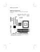
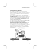
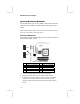
Connect the case switches and indicator LEDs to the PANEL1
header. Here is a list of the PANEL1 header’s pin assignments.
Pin Signal Pin Signal
1 HDD_LED_P 2 ACPI-LED
3 HDD_LED_N 4 ACPI-LED
5 RESET_SW_N 6 POWER-BT
7 RESET_SW_P 8 POWER-BT
9 KEY 10 KEY
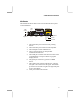
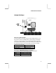
If there are a headphone jack or/and a microphone jack on the front
panel, connect the cables to the AUDIO1 header on the mainboard.
Here is a list of the AUDIO header’s pin assignments.
Pin Signal Pin Signal
1 AUD_MIC 2 AUD_GND
3 AUD_MIC_BIAS 4 AUD_VCC
5 AUD_FPOUT_R 6 GND
7 HP_ON 8 KEY
9 AUD_FPOUT_L 10 GND
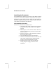
If there is another power-on indicator LED installed in the
system chassis, connect the LED to the
PLED1 header.
Pin Signal
1 GROUND
2 NC
3 POWER
15