
User`s manual


Mainboard User’s Manual
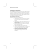
Optional Extension Brackets
For this mainboard, you can also obtain a USB module extension
bracket for more USB ports. Install them by following the steps
below.
Note: All the ribbon cables used on the extension brackets have a
red stripe on the Pin-1 side of the cable.
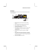
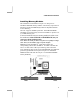
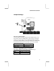
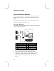
Extended USB Module
This module bracket has four USB 2.0 ports for more USB devices
(USB 2.0 port USB2, USB3).
1
USB2
Pin Signal Pin Signal
1 VERG_FP_USBPWR0 2 VERG_FP_USBPWR0
3 USB_FP_P0- 4 USB_FP_P1-
5 USB_FP_P0+ 6 USB_FP_P1+
7 GROUND 8 GROUND
9 KEY 10 NC
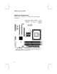
1. Locate the USB2/USB3 header on the mainboard.
2. Plug the bracket cable onto the USB2/USB3 header.
3. In the system chassis, remove a slot cover from one of the
expansion slots and install the extension bracket in the
opening. Secure the extension bracket to the chassis with a
screw.
USB3
1
16