This publication, including all photographs, illustrations and software, is protected under international copyright laws, with all rights reserved. Neither this manual, nor any of the material contained herein, may be reproduced without the express written consent of the manufacturer. The information in this document is subject to change without notice.
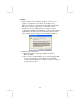
Notice: 1. Owing to Microsoft’s certifying schedule is various to every supplier, we might have some drivers not certified yet by Microsoft. Therefore, it might happen under Windows XP that a dialogue box (shown as below) pop out warning you this software has not passed Windows Logo testing to verify its compatibility with Windows XP. Please rest assured that our RD department has already tested and verified these drivers. Click the “Continue Anyway” button and go ahead the installation. 2. USB 2.
Table of Contents Trademarks .............................................................................. I Chapter 1: Introduction....................................................................1 Key Features............................................................................2 Package Contents.....................................................................5 Static Electricity Precautions...................................................6 Pre-Installation Inspection......................
IV
Chapter 1 Introduction This mainboard has a Socket-A support for the AMD K7 processors. The Socket-A processor’s front-side bus speed is 266MHz. This mainboard has a KM266 chipset that supports one 4X AGP slot for highly graphics display, 100/133 MHz DDR, and Ultra DMA ATA100/133 function to provide outstanding high system performance under all types of system operations.
Key Features The key features of this mainboard include: Socket-A Processor Support ♦ Supports AMD Athlon XP/Athlon/Duron processors ♦ Supports 266 MHz Front-Side Bus Chipset There are VIA KM266 Northbridge and VT8235 Southbridge in this chipset in accordance with an innovative and scalable architecture with proven reliability and performance.
Power Supply and Power Management ♦ ATX power supply connector ♦ ACPI and previous PMU support, suspend switch, keyboard power on/off ♦ Supports Wake on LAN VGA ♦ ♦ ♦ ♦ ♦ ♦ ♦ Single cycle 128-bit 3D architecture 128-bit 2D graphic engine 8/16/32 MB frame buffer using system memory Supports AGP 4X 266 MHz mode up to 1GB/s bandwidth Supports 250MHz RAMDAC 2D/3D resolutions up to 1920x1440 Supports AGP Rev. 2.0 Spec. Compliant AC97 Codec ♦ Compliant with AC’97 2.
Built-in Ethernet LAN (optional) ♦ 10Base-T/100Base-TX Physical Layer Solution ♦ Dual Speed – 100/10 Mbps ♦ MII Interface to Ethernet Controller/Configuration & Status ♦ Auto Negotiation: 10/100, Full/Half Duplex ♦ Meet All Applicable IEEE802.3, 10Base-T and 100BaseTX Standards USB 2.0 ♦ Compliant with Universal Serial Bus Specification Revision 2.0 ♦ Compliant with Intel’s Enhanced Host Controller Interface Specification Revision 0.
Dimensions ♦ Micro ATX form factor (24.4cm x 19cm) Package Contents Your mainboard package ships with the following items: The mainboard The User’s Manual One diskette drive ribbon cable (optional) One IDE drive ribbon cable Software support CD Optional Accessories You can purchase the following optional accessories for this mainboard.
Static Electricity Precautions Components on this mainboard can be damaged by static electricity. Take the following precautions when unpacking the mainboard and installing it in a system. 1. Keep the mainboard and other components in their original static-proof packaging until you are ready to install them. 2. During installation, wear a grounded wrist strap if possible. If you don’t have a wrist strap, discharge static electricity by touching the bare metal of the system chassis. 3.
Chapter 2 Mainboard Installation To install this mainboard in a system, please follow these instructions in this chapter: Identify the mainboard components Install a CPU Install one or more system memory modules Make sure all jumpers and switches are set correctly Install this mainboard in a system chassis (case) Connect any extension brackets or cables to connecting headers on the mainboard Install other devices and make the appropriate connections to the mainboard connecting headers Note: 1.
Mainboard Components This diagram below identifies major components on the mainboard. Note: Any jumpers on your mainboard that do not appear in the illustration above are for testing only. I/O Ports The illustration below shows a side view of the built-in I/O ports on the mainboard.
PS/2 Mouse PS/2 Keyboard LPT1 COM1 VGA LAN Port (optional) USB Ports Use the upper PS/2 port to connect a PS/2 pointing device. Use the lower PS/2 port to connect a PS/2 keyboard. Use LPT1 to connect printers or other parallel communications devices. Use the COM port to connect serial devices such as mice or fax/modems. COM1 is identified by the system as COM1. Use the VGA port to connect VGA devices. Connect an RJ-45 jack to the LAN port to connect your computer to the Network.
3. Push the locking lever down and hook it under the latch on the edge of socket. 4. Apply thermal grease to the top of the CPU. 5. Lower the CPU fan/heatsink unit onto the CPU and CPU socket, and then use the retention module clamps to snap the fan/heatsink into place. 6. Plug the CPU fan power cable into the CPU cooling fan power supply (CPUFAN1) on the mainboard. Install Memory Modules This mainboard accommodates two 184-pin 2.
Installation Procedure These modules can be installed with up to 2 GB system memory. Refer to the following to install the memory module. Refer to the following to install the memory modules. 1. Push the latches on each side of the DIMM socket down. 2. Align the memory module with the socket. The DIMM sockets are keyed with notches and the DIMMs are keyed with cutouts so that they can only be installed correctly. 3.
Jumper JP2: Clear CMOS Memory This jumper can clear the CMOS memory. You may need to clear the CMOS memory if the settings in the Setup Utility are incorrect that your mainboard can’t operate. To clear the CMOS memory, disconnect all the power cables, and then move the jumper cap into the CLEAR setting for a few seconds. Function Normal Clear CMOS Jumper Setting Short Pins 1-2 Short Pins 2-3 Jumper JP3: CPU Clock Selector This 3-pin jumper selects the processor 133 MHz or 100 MHz.
Connect the power connector from the power supply to the ATX1 connector on the mainboard. CPUPW1 is the CPU Vcore power connector. If there is a cooling fan installed in the system chassis, connect the cable from the cooling fan to the SYSFAN1 fan power connector on the mainboard. Connect the case switches and indicator LEDs to the PANEL1 header.
AUDIO2: Front Panel Audio Header This header allows the user to install auxiliary front-oriented microphone and line-out ports for easier access. Pin 1 3 5 7 9 Signal AUD_MIC AUD_MIC_BIAS AUD_FPOUT_R HP_ON AUD_FPOUT_L Pin 2 4 6 8 10 Signal AUD_GND AUD_VCC AUD_RET_R KEY AUD_RET_L Note: If you want to connect the front panel sound jack, you have to remove jumper caps of Pin(5-6) and Pin(9-10) from the AUDIO2 header.
READER1: USB Card Reader Connector (optional) This connector is for connecting internal USB card reader. You can use a card reader to read or transfer files and digital images to your computer. Pin 1 3 5 Signal STANDBY 5V USB+ KEY Pin 2 4 Signal USBGND The READER1 is shared with the lower USB port located beside the VGA port of the I/O back panel. Please see “I/O Ports” for more information. Please check the pin assignment of the cable and the USB header on the mainboard.
Install Other Devices Install and connect any other devices in the system following the steps below. 1 1 1 IDE2 IDE1 FDC1 Floppy Disk Drive The mainboard ships with a floppy disk drive cable that can support one or two drives. Drives can be 3.5” or 5.25” wide, with capacities of 360K, 720K, 1.2MB, 1.44MB, or 2.88MB. Install your drives and connect power from the system power supply. Use the cable provided to connect the drives to the floppy disk drive connector FDC1.
If you want to install more IDE devices, you can purchase a second IDE cable and connect one or two devices to the Secondary IDE channel connector IDE2 on the mainboard. If you have two devices on the cable, one must be Master and one must be Slave. Internal Sound Connections If you have installed a CD-ROM drive or DVD-ROM drive, you can connect the drive audio cable to the onboard sound system. CD2 1 When you first start up your system, the BIOS should automatically detect your CD-ROM/DVD drive.
Expansion Slots This mainboard has one AGP, one CNR and two 32-bit PCI slots. AGP1 CNR1 PCI2 PCI1 Follow the steps below to install a PCI/AGP/CNR expansion card. 1. Locate the CNR, AGP or PCI slots on the mainboard. 2. Remove the blanking plate of the slot from the system chassis. 3. Install the edge connector of the expansion card into the slot. Ensure the edge connector is correctly seated in the slot. 4. Secure the metal bracket of the card to the system chassis with a screw.
Chapter 3 BIOS Setup Utility Introduction The BIOS Setup Utility records settings and information of your computer, such as date and time, the type of hardware installed, and various configuration settings. Your computer applies the information to initialize all the components when booting up and basic functions of coordination between system components. If the Setup Utility configuration is incorrect, it may cause the system to malfunction. It can even stop your computer booting properly.
Running the Setup Utility Every time you start your computer, a message appears on the screen before the operating system loading that prompts you to “Hit if you want to run SETUP”. Whenever you see this message, press the Delete key, and the Main menu page of the Setup Utility appears on your monitor. AMIBIOS SIMPLE SETUP UTILITY – VERSION 1.21.12 (C) 2000 American Megatrends, Inc.
Standard CMOS Setup Page Use this page to set basic information such as the date, the time, the IDE devices, and the diskette drives. If you press the F3 key, the system will automatically detect and configure the hard disks on the IDE channels. AMIBIOS SETUP – STANDARD CMOS SETUP (C) 2000 American Megatrends, Inc.
Advanced Setup Page Use this page to set more advanced information about your system. Take some care with this page. Making changes can affect the operation of your computer. AMIBIOS SETUP – ADVANCED SETUP (C) 2000 American Megatrends, Inc. All Rights Reserved Quick Boot 1st Boot Device 2nd Boot Device 3rd Boot Device Try Other Boot Devices S.M.A.R.T.
BootUp NumLock Floppy Drive Swap Floppy Drive Seek Password Check Boot to OS/2 > 64MB L2 Cache System BIOS Cacheable DRAM Timing by SPD DRAM CAS# Latency DRAM Bank Interleave This item determines if the Num Lock key is active or inactive at system start-up time. If you have two diskette drives installed and you enable this item, drive A becomes drive B and drive B becomes drive A. If you enable this item, your system will check all floppy disk drives at start up.
AGP Mode AGP Comp. Driving Manual AGP Comp. Driving AGP Aperture Size CLK Gen Spread Spectrum Auto Detect DIMM/PCI Clk This item provides the OnBoard VGA mode with three options of 1,2, 4 multiplied frequency. This item signals the auto or manual driving current on AGP cards. Some AGP cards need stronger driving current for operation. We recommend you set this item to be default value. This item decides the AGP current driving value while AGP Driving is set to Manual.
ACPI Aware O/S Power Management Hard Disk Time Out Suspend Time Out (Minute) LAN/Ring Power On Keyboard Power On Wake up key Wake up password PowerOn by RTC Alarm / Date / Hour / Minute / Second This item supports ACPI (Advanced Configuration and Power management Interface). Use this item to enable or disable the ACPI feature. This item enables or disables a power management scheme. If you enable power management, there are some options for you to decide the power management operation.
PCI / Plug and Play Setup Page This page sets some of the parameters for devices installed on the PCI bus and devices that use the system plug and play capability. AMIBIOS SETUP – PCI / PLUG AND PLAY SETUP (C) 2000 American Megatrends, Inc.
Load Optimal Settings If you select this item and press Enter a dialog box appears. If you press Y, and then Enter, the Setup Utility loads a set of fail-safe default values. These default values are not very demanding and they should allow your system to function with most kinds of hardware and memory chips. Note: It is highly recommend that users enter this option to load optimal values for accessing the best performance.
OnBoard FDC OnBoard Serial PortA OnBoard IR Port Onboard Parallel Port Parallel Port Mode Parallel Port IRQ Parallel Port DMA OnBoard IDE Ethernet Device Audio Device Modem Device USB Controller USB Device Legacy Support This item enables or disables the onboard floppy disk drive interface. These items enable or disable the onboard COM1 serial port, and assign a port address. This item enables or disables the Infrared port, and assigns a port address.
ThumbDrive Support for DOS Enable this item to make a small portion of memory storage device for the USB ports. CPU PnP Setup Page This page lets you manually configure the mainboard for the CPU. The system will automatically detect the kind of CPU that you have installed and make the appropriate adjustments to the items on this page. AMIBIOS SETUP – CPU PnP SETUP ©2000 American Megatrends, Inc.
Hardware Monitor Page This page sets some of the parameters for the hardware monitoring function of this mainboard. AMIBIOS SETUP – HARDWARE MONITOR (C) 2000 American Megatrends, Inc. All Rights Reserved *** System Hardware *** Vcore Vcc 2.5V Vcc 3.3V Vcc 5 V +12V -12V SB5V VBAT SYSTEM Fan Speed CPU Fan Speed SYSTEM Temperature CPU Temperature System / CPU Temperature FANs & Voltage Measurements 1.616 V 2.496 V 3.392 V 4.945 V 12.032V - 12.032V 5.026 V 3.
Change or Remove the Password Highlight this item, press Enter and type in the current password. At the next dialog box, type in the new password, or just press Enter to disable password protection. Exit Highlight this item and press Enter to save the changes that you have made in the Setup Utility configuration and exit the program. When the Save and Exit dialog box appears, press Y to save and exit, or press N to exit without saving.
Chapter 4 Software & Applications Introduction This chapter describes the contents of the support CD-ROM that comes with the mainboard package. The support CD-ROM contains all useful software, necessary drivers and utility programs to properly run our products. More program information is available in a README file, located in the same directory as the software. To run the support CD, simply insert the CD into your CD-ROM drive.
Installing Support Software 1.Insert the support CD-ROM disc in the CD-ROM drive. 2.When you insert the CD-ROM disc in the system CD-ROM drive, the CD automatically displays an Auto Setup screen. 3.The screen displays three buttons of Setup, Browse CD and Exit on the right side, and three others Setup, Application and ReadMe at the bottom. Please see the following illustration. The Setup button runs the software auto-installing program as explained in next section.
Auto-Installing under Windows 98/ME/2000/XP If you are under Windows 98/ME/2000/XP, please click the Setup button to run the software auto-installing program while the Auto Setup screen pops out after inserting the support CD-ROM: 1. The installation program loads and displays the following screen. Click the Next button. 2. Select the items that you want to setup by clicking on it (the default options are recommended). Click the Next button to proceed. 3. The support software will automatically install.
Installing under Windows NT or Manual Installation If you are under Windows NT, the auto-installing program doesn’t work out; or you have to do the manual installation, please follow this procedure while the Auto Setup screen pops out after inserting the support CD-ROM: 1. Click the ReadMe to bring up a screen, and then click the Install Path at the bottom of the screen. 2. Find out your mainboard model name and click on it to obtain its correct driver directory. 3.