
User`s manual

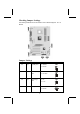

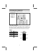
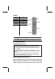


Table Of Contents
- Preface
- Chapter 1
- Introducing the Mainboard
- Chapter 2
- Installing the Mainboard
- Safety Precautions
- Quick Guide
- Installing the Mainboard in a Case
- Checking Jumper Settings
- Connecting Case Components
- Installing Hardware
- Installing the Processor
- Installing Memory Modules
- Installing a Hard Disk Drive/CD-ROM
- Installing a Floppy Diskette Drive
- Installing Add-on Cards
- Connecting Optional Devices
- Connecting I/O Devices
- Chapter 3
- Using BIOS
- About the Setup Utility
- Using BIOS
- Standard CMOS Features
- Advanced BIOS Setup Option
- Anti-Virus Protection (Disabled)
- Y2K Monitor (Disabled)
- CPU Internal Cache CPU Internal Cache (Enabled)
- External Cache (Enabled)
- CPU L2 Cache ECC Checking (Enabled)
- Quick Power On Self Test (Enabled)
- 1st/2nd/3rd Boot Device (Floppy/HDD-0/LS120)
- Boot Other Device (Enabled)
- Swap Floppy Drive (Disabled)
- Boot Up Floppy Seek (Enabled)
- Boot Up NumLock Status (On)
- ATA 66/100 IDE Cable MSG (Enabled)
- Gate A20 Option (Fast)
- Typematic Rate Setting (Disabled)
- Security Option (Setup)
- OS Select For DRAM > 64 MB (Non-OS2)
- HDD S.M.A.R.T Capability (Disabled)
- Report No FDD For WIN95 (Yes)
- Advanced Chipset Features Option
- Integrated Peripherals Option
- OnChip IDE Device
- OnChip PCI Device
- SuperIO Device
- POWER ON Function (Hot KEY)
- KB Power ON Password
- Hot Key Power ON (Ctrl-F12)
- Onboard FDC Controller (Enabled)
- Onboard Serial Port 1 (3F8/IRQ4)
- Onboard Serial Port 2 (2F8/IRQ3)
- UART Mode Select (Normal)
- UR2 Duplex Mode (Half)
- Onboard Parallel Port (378/IRQ7)
- Parallel Port Mode (ECP)
- ECP Mode Use DMA (3)
- Game Port Address (201)
- Midi Port Address (330)
- Midi Port IRQ (10)
- Init Display First (PCI Slot)
- OnChip USB Controller (All Enabled)
- USB Keyboard Support (Disabled)
- IDE HDD Block Mode (Enabled)
- Power Management Setup Option
- Power Management Timeouts
- Wake Up Calls
- ACPI Function (Enabled)
- ACPI Suspend Type (S1 (POS))
- Power Management Option (User Define)
- HDD Power Down (Disable)
- Suspend Mode (Disable)
- Video Off Option (Suspend --> Off)
- Video Off Method (DPMS Support)
- MODEM Use IRQ (3)
- Soft-Off by PWRBTN (Instant-Off)
- AC Resume Function (Always Off)
- IRQ/Event Activity Detect
- Press
to return to the previous screen. - PNP/PCI Configuration Option
- PC Health Status Option
- Frequency/Voltage Control
- Load Fail-Safe Defaults Option
- Load Optimized Defaults Option
- Set Password Option
- Save & Exit Setup Option
- Exit Without Saving
- Chapter 4
- Using the Mainboard Software

5. Plug the CPU fan power cable into the CPU cooling fan power supply on the
mainboard (CPUFAN1).
Note: After you have assembled the system, you must set the correct clock
speed and frontside bus (FSB) speed. Check the jumper section in Appen-
dix A and refer to Chapter 3 “Frequency Voltage Control” for more
information.
Installing Memory Modules
This mainboard accommodates 184-pin 2.5V unbuffered Double Data Rate
(DDR) SDRAM memory modules. The memory chips must be standard or
registered SDRAM (Synchronous Dynamic Random Access Memory). The
memory bus runs at 100 MHz.
Installation Procedure
The mainboard accommodates three
memory modules. You must install at
least one module in any of the three
slots. Each module can be installed
with 32 MB to 512 MB of memory;
total memory capacity is 1.5 GB.
Refer to the following to install the memory modules.
1. Push the latches on each side of the DIMM slot down.
2. Align the memory module with the slot. The DIMM slots are keyed with
notches and the DIMMs are keyed with cutouts so that they can only be
installed correctly.
3. Check that the cutouts on the
DIMM module edge connector
match the notches in the
DIMM slot:
Cutout
Notch
Latch
Latch
4. Install the DIMM module into
the slot and press it firmly
down until it seats correctly.
The slot latches are levered
upwards and latch on to the
edges of the DIMM.
5. Install any remaining DIMM
modules.
13