Motherboard User’s Guide This publication, including photographs, illustrations and software, is under the protection of international copyright laws, with all rights reserved. Neither this manual, nor any of the material contained herein, may be reproduced without the express written consent of the manufacturer. The information in this document is subject to change without notice.
Motherboard User’s Guide Table of Contents Trademark ............................................................................................................ i Chapter 1: Introduction ..................................................................................... 1 Key Features .................................................................................................................... 1 Package Contents .......................................................................................
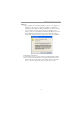
Motherboard User’s Guide Notice: 1. Owing to Microsoft’s certifying schedule is various to every supplier, we might have some drivers not certified yet by Microsoft. Therefore, it might happen under Windows XP that a dialogue box (shown as below) pops out warning you this software has not passed Windows Logo testing to verify its compatibility with Windows XP. Please rest assured that our RD department has already tested and verified these drivers.
Motherboard User’s Guide Chapter 1 Introduction This motherboard has a Socket-754 supporting the newest and advanced AMD Athlon 64/Sempron with HyperTransport Technology processors, Front-Side Bus (FSB) speeds up to 800 MHz and system bus to 1600 MT/s. This motherboard integrates the VIA K8M800 Northbridge and VT8237 Southbridge that supports the Serial ATA interface for high-performance and mainstream desktop PCs, and the built-in USB 2.0 providing higher bandwidth.
Motherboard User’s Guide • • • • • • • • High Performance HyperTransport CPU Interface -- Processor interface via HyperTransport interface Full Featured Accelerated Graphics Port (AGP) Controller − − AGP v3.0 compliant 8X / 4X transfer mode with Fast Write Support − − Pipelined split-transaction long-burst transfers up to 2.
Chapter 1: Introduction • • • • • Support for 3.3v digital, 5v analog power supply and low power consumption management Three analog line-level stereo inputs with 5-bit volume control: LINE_IN, CD, AUX Front-Out, Surround-Out, MIC-In and LINE-In Jack Sensing Two analog line-level mono input Standard 48-Pin LQFP Onboard I/O Ports • Two PS/2 ports for mouse and keyboard • One serial port • One parallel port • One VGA port • Four back-panel USB2.
Motherboard User’s Guide • CPU and memory timing The firmware can also be used to set parameters for different processor clock speeds. Dimensions • Micro ATX form factor of 244 x 192 mm Note: Hardware specifications and software items are subject to change without notification.
Chapter 2: Motherboard Installation Chapter 2 Motherboard Installation To install this motherboard in a system, please follow these instructions in this chapter: Identify the motherboard components Install a CPU Install one or more system memory modules Make sure all jumpers and switches are set correctly Install this motherboard in a system chassis (case) Connect any extension brackets or cables to headers/connectors on the motherboard Install peripheral devices and make the appropriate conn
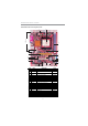
Motherboard User’s Guide Motherboard Components 2 I/O Ports 1 3 20 4 19 18 5 17 6 16 7 8 15 9 14 ITEM LABEL 1 PWR2 2 13 12 11 COMPONENTS Standard 4-Pin ATX Pow er connector 10 COLOR WHITE 3 CPU Socket Socket-754 for AMD Athlon 64/Sempron CPUs DIMM1/2 Tw o 184-pin DDR SDRAM sockets WHITE 4 FAN2 CPU Fan connector(3PIN) DARK RED 5 USB3/4 Front Panel USB headers YELLOW 6 IDE1 Primary IDE connector BLUE 7 IDE2 Sceondary IDE connector WHITE 8 SATA1/2 Serial ATA connectors BLAC
Chapter 2: Motherboard Installation I/O Ports The illustration below shows a side view of the built-in I/O ports on the motherboard. PS/2 Mouse Use the upper PS/2 port to connect a PS/2 pointing device. PS/2 Keyboard Use the low er PS/2 port to connect a PS/2 keyboard. Parallel Port (LPT1) Use the Parallel port to connect printers or other parallel communications devices. Serial Port (COM1) Use the COM port to connect serial devices such as mice or fax/modems.
Motherboard User’s Guide CPU Installation Procedure Follow these instructions to install the CPU: Socket-754 pin1 FAN2 1 1 2 3 4 5 6 Unhook the locking lever of the CPU socket. Pull the locking lever away from the socket and raising it to the upright position. Match the pin1 corner marked as the beveled edge on the CPU with the pin1 corner on the socket. Insert the CPU into the socket. Do not use force. Push the locking lever down and hook it under the latch on the edge of socket.
Chapter 2: Motherboard Installation DDR SDRAM is a type of SDRAM that supports data transfers on both edges of each clock cycle (the rising and falling edges), effectively doubling the memory chip’s data throughput. DDR DIMMs can synchronously work with 166 MHz or 200 MHz memory bus. DDR SDRAM provides 2.1 GB/s, 2.7 GB/s or 3.2GB/s data transfer rate when the bus is 133 MHz, 166 MHz or 200 MHz, respectively.
Motherboard User’s Guide Jumper Settings Connecting two pins with a jumper cap is SHORT; removing a jumper cap from these pins, OPEN. JP1 1 JP1: Clear CMOS Jumper Use this jumper to clear the contents of the CMOS memory. You may need to clear the CMOS memory if the settings in the Setup Utility are incorrect and prevent your motherboard from operating. To clear the CMOS memory, disconnect all the power cables from the motherboard and then move the jumper cap into the CLEAR setting for a few seconds.
Chapter 2: Motherboard Installation PWR2 PWR1 FAN1 1 PANEL1 1 Connect the power connector from the power supply to the PWR1 connector on the motherboard. PWR2 is a +12V connecotr for CPU Vcore power. If there is a cooling fan installed in the system chassis, connect the cable from the cooling fan to theFAN2 fan power connector on the motherboard. Connect the case switches and indicator LEDs to the PANEL1 header.
Motherboard User’s Guide Connecting Optional Devices Refer to the following for information on connecting the motherboard’s optional devices: USB4 AUDIO2 1 USB3 1 1 1 SIR1 SPK1 1 SPK1: Speaker Header Connect the cable from the PC speaker to the SPK1 header on the motherboard. Pin 1 2 3 4 Signal SPKR NC NC +5V AUDIO2: Front Panel Audio Header This header allows the user to install auxiliary front-oriented microphone and line-out ports for easier access.
Chapter 2: Motherboard Installation Here is a list of USB pin assignments. Pin 1 3 5 7 9 Signal VERG_FP_USBPWR0 USB_FP_P0(-) USB_FP_P0(+) GROUND KEY Pin 2 4 6 8 10 Signal VERG_FP_USBPWR0 USB_FP_P1(-) USB_FP_P1(+) GROUND USB_FP_OC0 1. Locate the USB3/USB4 header on the motherboard. 2. Plug the bracket cable onto the USB3/USB4 header. 3. Remove a slot cover from one of the expansion slots on the system chassis. Install an extension bracket in the opening.
Motherboard User’s Guide Install Other Devices Install and connect any other devices in the system following the steps below. IDE2 IDE1 1 SATA2 SATA1 1 FDD1 1 Floppy Disk Drive The motherboard ships with a floppy disk drive cable that can support one or two drives. Drives can be 3.5" or 5.25" wide, with capacities of 360K, 720K, 1.2MB, 1.44MB, or 2.88MB. Install your drives and connect power from the system power supply.
Chapter 2: Motherboard Installation If you want to install more IDE devices, you can purchase a second IDE cable and connect one or two devices to the Secondary IDE channel connector IDE2 on the motherboard. If you have two devices on the cable, one must be Master and one must be Slave.
Motherboard User’s Guide Here is a list of CD1 pin assignments. Pin 1 2 3 Signal CD IN L GND GND 4 CD IN R Expansion Slots This motherboard has one AGP, one CNR and two 32-bit PCI slots. AGP1 PCI1 PCI2 CNR1 Follow the steps below to install an AGP/CNR/PCI expansion card. 1. Locate the AGP, CNR or PCI slots on the mainboard. 2. Remove the blanking plate of the slot from the system chassis. 3. Install the edge connector of the expansion card into the slot.
Chapter 2: Motherboard Installation 4. Secure the metal bracket of the card to the system chassis with a screw. 8X AGP Slot You can install a graphics adapter that supports the 8X AGP specification and has a 8X AGP edge connector in the AGP slot. CNR Slot You can install the CNR (Communications and Networking Riser) cards in this slot, including LAN, Modem, and Audio functions. PCI Slots You can install the 32-bit PCI interface expansion cards in the slots.
Motherboard User’s Guide Chapter 3 BIOS Setup Utility Introduction The BIOS Setup Utility records settings and information of your computer, such as date and time, the type of hardware installed, and various configuration settings. Your computer applies the information to initialize all the components when booting up and basic functions of coordination between system components. If the Setup Utility configuration is incorrect, it may cause the system to malfunction.
Chapter 3: BIOS Setup Utility Some options on the main menu page lead to tables of items with installed values that you can use cursor arrow keys to highlight one item, and press PgUp and PgDn keys to cycle through alternative values of that item. The other options on the main menu page lead to dialog boxes requiring your answer OK or Cancel by selecting the [OK] or [Cancel] key. If you have already changed the setup utility, press F10 to save those changes and exit the utility.
Motherboard User’s Guide Advanced Setup Page This page sets up more advanced information about your system. Handle this page with caution. Any changes can affect the operation of your computer. CMOS SETUP UTILITY – Copyright (C) 1985-2003, American Megatrends, Inc.
Chapter 3: BIOS Setup Utility CAS Latency (CL) This item determines the operation of DRAM memory CAS (column address strobe). It is recommended that you leave this item at the default value. The 2T setting requires faster memory that specifically supports this mode. TRCD/TRAS/TRP These items adjust the efficiency and stability of DRAM. Auto detect DIMM/PCI Clock When this item is enabled, BIOS will disable the clock signal of free DIMM/PCI slots.
Motherboard User’s Guide Features Setup Page This page sets up some parameters for peripheral devices connected to the system. CMOS SETUP UTILITY – Copyright (C) 1985-2003, American Megatrends, Inc.
Chapter 3: BIOS Setup Utility OnBoard SATA-IDE Use this item to enable the onboard SATA-IDE channel. Audio Device This item enables or disables the AC’97 audio chip. Modem Device This item enables or disables the onboard Modem. Ethernet Device This item enables or disables the onboard Ethernet LAN. OnBoard USB Function Enable this item if you plan to use the USB ports on this motherboard. USB Function For DOS Enable this item if you plan to use the USB ports on this motherboard in a DOS environment.
Motherboard User’s Guide Suspend Time Out This sets the timeout for Suspend mode in minutes. If the time selected passes without any system activity, the computer will enter power-saving Suspend mode. Resume On RTC Alarm / RTC Alarm Date (Days) / System Time The system can be turned off with a software command. If you enable this item, the system can automatically resume at a fixed time based on the system’s RTC (realtime clock). Use the items below this one to set the date and time of the wake-up alarm.
Chapter 3: BIOS Setup Utility Share Memory Size This item lets you allocate a portion of the main memory for the onboard VGA display application with several options. Allocate IRQ to PCI VGA If this item is enabled, an IRQ will be assigned to the PCI VGA graphics system. You set this value to No to free up an IRQ. PCI IDE BusMaster This item enables or disables the DMA under DOS mode. We recommend you to leave this item at the default value.
Motherboard User’s Guide CPU PnP Setup Page This page helps you manually configure the mainboard for the CPU. The system will automatically detect the type of installed CPU and make the appropriate adjustments to the items on this page. CMOS SETUP UTILITY – Copyright (C) 1985-2003, American Megatrends, Inc. CPU PnP Setup CPU Type: AMD Athlon (tm) CPU Over-clocking Func.
Chapter 3: BIOS Setup Utility Hardware Monitor Page This page sets up some parameters for the hardware monitoring function of this motherboard. CMOS SETUP UTILITY – Copyright (C) 1985-2003, American Megatrends, Inc. Hardware Monitor Setup *** System Hardware Monitor*** Vcore Vdimm Vcc5V SB3V CPU FAN2 Speed SYSTEM FAN1 Speed SYSTEM Temperature CPU Temperature :1.463V :2.512V :5.026V :3.
Motherboard User’s Guide Chapter 4 Software & Applications Introduction This chapter describes the contents of the support CD-ROM that comes with the motherboard package. The support CD-ROM contains all useful software, necessary drivers and utility programs to properly run our products. More program information is available in a README file, located in the same directory as the software. To run the support CD, simply insert the CD into your CD-ROM drive.
Chapter 4: Software & Applications The Browse CD button is a standard Windows command that you can check the contents of the disc with the Windows 98 file browsing interface. The Exit button closes the Auto Setup window. To run the program again, reinsert the CD-ROM disc in the drive; or click the CD-ROM driver from the Windows Explorer, and click the Setup icon. The Application button brings up a software menu. It shows the bundled software that this mainboard supports.
Motherboard User’s Guide 3 The support software will automatically install. Once any of the installation procedures start, software is automatically installed in sequence. You need to follow the onscreen instructions, confirm commands and allow the computer to restart as few times as needed to complete installing whatever software you selected. When the process is finished, all the support software will be installed and start working.