Table of Contents Introduction Instrument Cluster 4 10 Warning and control lights Gauges 10 14 Entertainment Systems 17 AM/FM stereo with CD AM/FM stereo cassette with CD Climate Controls Manual heating and air conditioning Electronic automatic temperature control Rear passenger climate control 17 21 31 31 32 35 Lights 37 Driver Controls 48 Windshield wiper/washer control Steering wheel adjustment Power windows Mirrors Speed control Message center 48 49 54 55 56 68 Locks and Security 84 Ke
Table of Contents Seating and Safety Restraints Seating Safety restraints Air bags Child restraints Driving 98 108 121 129 142 Starting Brakes Transmission operation Trailer towing 142 145 148 166 Roadside Emergencies 172 Getting roadside assistance Hazard flasher switch Fuel pump shut-off switch Fuses and relays Changing tires Jump starting Wrecker towing Customer Assistance The dispute settlement board Utilizing the mediation/arbitration Getting assistance outside the U.S.
Table of Contents Maintenance and Specifications Engine compartment Engine oil Battery Fuel information Low tire warning system Part numbers Refill capacities Lubricant specifications 215 218 221 226 234 252 253 254 256 Accessories 262 Index 266 All rights reserved.
Introduction CALIFORNIA Proposition 65 Warning WARNING: Engine exhaust, some of its constituents, and certain vehicle components contain or emit chemicals known to the State of California to cause cancer and birth defects or other reproductive harm. In addition, certain fluids contained in vehicles and certain products of component wear contain or emit chemicals known to the State of California to cause cancer and birth defects or other reproductive harm.
Introduction SAFETY AND ENVIRONMENT PROTECTION Warning symbols in this guide How can you reduce the risk of personal injury and prevent possible damage to others, your vehicle and its equipment? In this guide, answers to such questions are contained in comments highlighted by the warning triangle symbol. These comments should be read and observed.
Introduction SPECIAL NOTICES Special instructions For your added safety, your vehicle is fitted with sophisticated electronic controls. Please read the section Supplemental Restraint System (SRS) in the Seating and safety restraints chapter. Failure to follow the specific warnings and instructions could result in personal injury. Front seat mounted rear facing child or infant seats should NEVER be used in front of a passenger side air bag unless the air bag can be and is turned OFF.
Introduction Emission warranty The New Vehicle Limited Warranty includes Bumper-to-Bumper Coverage, Safety Restraint Coverage, Corrosion Coverage, and 7.3L Power Stroke Diesel Engine Coverage. In addition, your vehicle is eligible for Emissions Defect and Emissions Performance Warranties. For a detailed description of what is covered and what is not covered, refer to the Warranty Guide that is provided to you along with your Owner’s Guide.
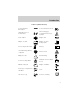
Introduction These are some of the symbols you may see on your vehicle.
Introduction Vehicle Symbol Glossary Power Windows Front/Rear Power Window Lockout Child Safety Door Lock/Unlock Interior Luggage Compartment Release Symbol Panic Alarm Engine Oil Engine Coolant Engine Coolant Temperature Do Not Open When Hot Battery Avoid Smoking, Flames, or Sparks Battery Acid Explosive Gas Fan Warning Power Steering Fluid Maintain Correct Fluid Level Emission System Engine Air Filter Passenger Compartment Air Filter Jack Check fuel cap Low tire warning MAX MIN 9
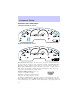
Instrument Cluster WARNING LIGHTS AND CHIMES Standard instrument cluster CHECK GAGE O/D OFF SERVICE ENGINE SOON BRAKE DOOR AJAR LOW WASH CHECK FUEL CAP TRIP Optional instrument cluster Warning lights and gauges can alert you to a vehicle condition that may become serious enough to cause expensive repairs. A warning light may illuminate when a problem exists with one of your vehicle’s functions. Many lights will illuminate when you start your vehicle to make sure the bulb works.
Instrument Cluster chapter. If the light is blinking, engine misfire is occurring which could damage your catalytic converter. Drive in a moderate fashion (avoid heavy acceleration and deceleration) and have your vehicle serviced immediately. Under engine misfire conditions, excessive exhaust temperatures could damage the catalytic converter, the fuel system, interior floor coverings or other vehicle components, possibly causing a fire.
Instrument Cluster Air bag readiness: If this light fails to illuminate when ignition is turned to ON, continues to flash or remains on, have the system serviced immediately. A chime will also sound when a malfunction in the supplemental restraint system has been detected. Safety belt: Reminds you to fasten your safety belt. A chime will also sound to remind you to fasten your safety belt. Charging system: Illuminates when the battery is not charging properly.
Instrument Cluster Speed control: Illuminates when the speed control is activated. Turns off when the speed control system is deactivated. Low Washer (if equipped): Illuminates when the windshield washer fluid is low. LOW WASH Turn signal: Illuminates when the left or right turn signal or the hazard lights are turned on. If the indicators stay on or flash faster, check for a burned out bulb. High beams: Illuminates when the high beam headlamps are turned on.
Instrument Cluster GAUGES Standard instrument cluster gauges CHECK GAGE O/D OFF SERVICE ENGINE SOON BRAKE DOOR AJAR LOW WASH CHECK FUEL CAP Optional instrument cluster gauges Speedometer: Indicates the current vehicle speed.
Instrument Cluster Engine coolant temperature gauge: Indicates engine coolant temperature. At normal operating temperature, the needle will be in the normal range (between “H” and “C”). If it enters the red section, the engine is overheating. Stop the vehicle as soon as safely possible, switch off the engine and let the engine cool. Never remove the coolant reservoir cap while the engine is running or hot. Odometer: Registers the total kilometers (miles) of the vehicle.
Instrument Cluster Tachometer: Indicates the engine speed in revolutions per minute. Driving with your tachometer pointer continuously at the top of the scale may damage the engine. Battery voltage gauge: Indicates the battery voltage when the ignition is in the ON position. If the pointer moves and stays outside the normal operating range (as indicated by arrows), have the vehicle’s electrical system checked as soon as possible. Engine oil pressure gauge: Indicates engine oil pressure.
Entertainment Systems AUDIOPHILE IN-DASH SIX CD SOUND SYSTEM 1. Seek: Works in radio ro CD mode. Press and release / for previous/next SEEK strong station or track. 2. Rewind: In CD mode, press to reverse the CD Fast forward: In CD mode, press until desired selection is reached. 3. COMP (Compression): The compression feature operates in CD mode and brings soft and loud CD passages together for a more consistent listening level. Press the COMP control until COMP ON is displayed.
Entertainment Systems Press the DSP control again to access the occupancy modes. Use the SEL control to optimize the sound based upon the occupants in the vehicle. The following occupancy modes can be selected: • ALL SEATS • DRIVER SEAT • REAR SEATS 4. Mute: Press to MUTE playing media; press again return to playing media 5. Eject: Press to eject a CD. Press and hold to eject all loaded discs. 6. Bass: Press BASS; then press / to decrease/increase SEL the bass output.
Entertainment Systems Traffic: Allows you to hear traffic broadcasts. With the feature ON, press SEEK or SCAN to find a station broadcasting a traffic report (if it is broadcasting RDS data).Traffic information is not available in most U.S. markets. FIND Program type: Allows you to search RDS-equipped stations for a certain category of music format: Classic, Country, Info, Jazz, Oldies, R&B, Religious, Rock, Soft, Top 40. Show TYPE: Displays the station’s call letters and format.
Entertainment Systems Press and hold the volume control for five seconds. Press SEL to increase/decrease volume levels. The selected level will appear in the display. 14. Load: Press to load a CD. Press and hold to load up to six discs. 15. Shuffle: Press to play tracks in random order. 16. Scan: Press for a brief sampling of radio stations or CD tracks. Press again to stop. 17. Disc tune: Radio: Press or to manually tune down or up the radio frequency band.
Entertainment Systems PREMIUM AM/FM STEREO/CASSETTE/SINGLE CD 1. Power/volume: Press to turn ON/OFF; turn to increase/decrease volume. 2. Scan: Press to hear a brief SCAN sampling of all listenable stations, tape selections or CD tracks. Press again to stop. 3. CD Door: Insert a CD with the label side up. CD unit are designed to play commercially pressed 12 cm (4.75 in) audio compact discs only.
Entertainment Systems not be inserted into the CD player. The label may peel and cause the CD to become jammed. It is recommended that homemade CDs be identified with permanent felt tip marker rather than adhesive labels. Ball point pens may damage CDs. Please contact your dealer for further information. 4. Cassette door: Insert the cassette with the opening to the right. 5. Eject: Press to eject the cassette/CD. The radio will resume playing. 6. Tape: Press to start tape play.
Entertainment Systems to decrease minutes or TUNE to increase minutes. If your vehicle has a stand alone clock this control will not function. 10. Balance: Press BAL; then press / to shift sound to the SEL left/right speakers. Fade: Press FADE; then press SEL / to shift sound to the rear/front speakers. 11. Memory preset buttons: To set a station: Select frequency band AM/FM, tune to a station, press and hold a preset button until sound returns. 12. Shuffle (CD): Press to play tracks in random order. 13.
Entertainment Systems 16. Fast Forward (FF): Press for a slow advance, press and hold for a fast advance. 17. Rewind (REW): Press for a slow rewind, press and hold for a fast rewind. 18. Select (SEL): Use with Bass, Treble, Balance and Fade controls. FF 2 REW 1 SEL 19. Bass: Press BASS; then press SEL / to decrease/increase the bass output. Treble: Press TREB; then press / to decrease/increase SEL the treble output. 20. Tune: Works in radio mode only. / to change Press TUNE frequency down/up. 21.
Entertainment Systems MP3 AUDIO SYSTEM / to shift 1. Balance: Press sound to the left/right speakers. 2. Fade: Press / to shift sound to the rear/front speakers. 3. Scan: Press to hear a brief sampling of all listenable radio stations, CD or MP3 tracks. Press again to stop. 4. CLK: To set the clock press and hold the CLK control for the following functions: • To set the hour, press SEEK to the hours. / • To set the minutes, press TUNE DIR the minutes.
Entertainment Systems 5. EJ (Eject): Press to stop and eject a disc. If a disc is ejected and not removed, the player will automatically reload the disc and return to radio mode. 6. COMP (Compression): In CD and MP3 mode, press to adjust the soft and loud sounds together for a more consistent listening level. The compression icon (c) will illuminate in the display. 7. Shuffle: Press to engage random play on the CD or MP3 disc. SHF then ON will briefly appear in the display.
Entertainment Systems 13. Memory presets: To set a station: Select frequency band AM/FM; tune to a station, press and hold a preset button until sound returns. 14. CD door: Insert a CD with the label side up. 15. Tune/Directory: Press TUNE / to change the radio DIR frequency down/up or change the MP3 directories. 16. Seek: Press and release SEEK / for previous/next strong station selection or CD and MP3 tracks. 17. Power/volume: Press to turn ON/OFF; turn to increase or decrease volume levels. 18.
Entertainment Systems 21. Treble: Press / to decrease/increase the treble output. MP3 functions Your audio system is equipped with MP3 capability which allows you to listen to songs in MP3 flat file mode and MP3 directory mode. To engage MP3 flat file mode, insert an MP3 disc. If an MP3 disc is already present in the player, press the CD control. The MP3 icon will display while the player is in MP3 mode. While in MP3 flat file mode, press the MP3 DIR control to enter into MP3 directory mode.
Entertainment Systems Error messages You may experience an error message for the following situations: • NO DISC when the CD control is pressed and there is not a CD present. • DISC ERR when there is a damaged or unreadable disc. Such as, data discs containing no .mp3 files, or for data discs containing more than 255 files or directories. • CD ERR for any other disc malfunction.
Entertainment Systems Don’t: • Expose tapes to direct sunlight, extreme humidity, heat or cold. • Leave tapes in the cassette player for a long time when not being played. CD/CD PLAYER CARE Do: • Handle discs by their edges only. Never touch the playing surface. • Inspect discs before playing. Clean only with an approved CD cleaner and wipe from the center out. Don’t: • Expose discs to direct sunlight or heat sources for extended periods of time.
Climate Controls MANUAL HEATING AND AIR CONDITIONING SYSTEM 1. Temperature selection: Controls the temperature of the airflow in the vehicle. 2. Air flow selections: Controls the direction of the airflow in the vehicle. See the following for a brief description on each control. MAX A/C: Uses recirculated air through the instrument panel registers to cool the vehicle. This mode is more noisy than A/C, but is more economical and efficient and may help prevent undesirable odors from entering the vehicle.
Climate Controls To aid in side window defogging/demisting in cold weather: 1. Select 2. Select A/C 3. Modulate the temperature control to maintain comfort. 4. Set the fan speed to HI 5. Direct the outer instrument panel vents towards the side windows To increase airflow to the outer instrument panel vents, close the vents located in the middle of the instrument panel. Do not place objects on top of the instrument panel as these objects may become projectiles in a collision or sudden stop.
Climate Controls 3. Passenger side temperature control: Controls the temperature on the passenger side of the vehicle when in dual zone mode. To enter dual zone, press the passenger temperature control or DUAL. The passenger temperature will appear in the display. 4. Rear defrost control: Removes R ice and fog from the rear windshield. Press to turn on/off. 5.
Climate Controls 15. Fan Speed: Used to manually enable or disable the fan speed. EXT 16. EXT: Displays the outside air temperature. It will remain displayed until the EXT control is pressed again. The external temperature will be most accurate when the vehicle has been moving for a period of time. FC 17. Temperature conversion: Press to toggle between Fahrenheit and Celsius temperature on the DATC display only. The set point temperatures in Celsius will be displayed in half-degree increments.
Climate Controls Auxiliary system (if equipped) Your vehicle may be equipped with auxiliary climate controls. These allow the front or rear seat passengers to control airflow direction, temperature and fan level of the rear compartment to quickly heat or cool the entire vehicle. Front auxiliary controls: 1. Temperature control: 3 1 Determines temperature level.
Climate Controls Directs air to the floor of the third row seating. directs air to the overhead registers of the second and third row seating. The selected mode will illuminate on the temperature control. 3. Fan control: Determines fan speed levels. Floor console climate controls (if equipped) Controls the direction of the airflow to the rear of the vehicle. selects air flow from the console panel registers. selects air flow from the floor console registers.
Lights HEADLAMP CONTROL Turns the lamps off. Turns on the parking lamps, instrument panel lamps, license plate lamps and tail lamps. A Turns the headlamps on. Autolamp delay system The autolamp system sets the headlamps to turn on and off automatically. The autolamp control, located on the headlamp control, may be set to: • turn on the lamps automatically at night • turn off the lamps automatically during the daylight • keep the lamps on for up to three minutes after the key is turned to OFF.
Lights Always remember to turn on your headlamps at dusk or during inclement weather. The Daytime Running Light (DRL) System does not activate your tail lamps and generally may not provide adequate lighting during these conditions. Failure to activate your headlamps under these conditions may result in a collision. High beams Push the lever toward the instrument panel to activate. Pull the lever towards you to deactivate. OFF Flash to pass Pull the lever toward you to activate.
Lights Move the control to the full down position (past detent) to prevent interior lamps from illuminating when the doors are opened. AIMING THE HEADLAMPS The headlamps on your vehicle are properly aimed before leaving the assembly plant. If your vehicle is involved in an accident or if you have problems fixing the alignment of your headlamps, have them checked by a qualified service technician. Headlamp aim adjustment The headlamps on your vehicle can only be vertically adjusted.
Lights 5. Locate the vertical adjuster for each headlamp. Adjust the aim by turning the adjuster control either clockwise (to adjust down) or counterclockwise (to adjust up). Note: Use a 4 mm socket or box wrench to turn the vertical adjuster control. 6. Horizontal aiming is not required for this vehicle and is non-adjustable. TURN SIGNAL CONTROL • Push down to activate the left turn signal. • Push up to activate the right turn signal.
Lights NOTE: If your vehicle is equipped with the Remote Keyless Entry feature, the courtesy lamp will remain on for 25 seconds after the door is shut or until the ignition is turned to the ON position. To use the reading lamps: • Press the rocker control located near each reading lamp to turn it on. • Press the rocker control again to turn it off. Cargo/reading lamps The dome portion of the lamp or the center light can be turned on when the headlamp control is rotated fully up or when a door is opened.
Lights Function Number of bulbs Trade number Park/turn lamps 2 3157 AK (amber) (front) Headlamps 2 9007 Rear stop/turn/tail 4 3057 lamps Rear license plate 2 168 lamps Backup lamp 2 3156K High-mount brake 5 W5W lamps Side repeater 2 WY5W (amber) Front sidemarker 2 194 Rear sidemarker 2 194 Fog lamp 2 9145 Cargo lamp 1 211-2 Interior overhead lamp 1 912 (906) Front door courtesy 1 168 lamp Map lamps 2 168 (T10) Ashtray lamp 1 161 All replacement bulbs are clear in color except where noted.
Lights Replacing headlamp bulbs Do not touch the glass of a halogen bulb. 1. Turn off the headlamps and open the hood. 2. Remove two retainer pins, then pull headlamp forward. 3. Disconnect the electrical connector. 4. Remove the bulb retaining ring.
Lights 5. Carefully pull old bulb out of the lamp assembly Handle a halogen headlamp bulb carefully and keep out of children’s reach. Grasp the bulb only by its plastic base and do not touch the glass. The oil from your hand could cause the bulb to break the next time the headlamps are operated. Reverse steps to reinstall bulb(s). Replacing front parking/turn signal bulbs 1. Turn off the headlamps and open the hood. 2. Remove the two headlamp retainer pins, then pull headlamp forward.
Lights 3. Remove the bulb socket from the lamp assembly. 4. Carefully pull old bulb out of the lamp assembly Handle a halogen headlamp bulb carefully and keep out of children’s reach. Grasp the bulb only by its plastic base and do not touch the glass. The oil from your hand could cause the bulb to break the next time the headlamps are operated. Reverse steps to reinstall bulb(s).
Lights Replacing side repeater bulbs 1. Turn the headlamp switch to off. 2. Carefully pry the lamp assembly away from the fender. 3. Rotate the bulb socket counterclockwise to remove it from the lamp assembly. 4. Pull the bulb straight out. Reverse steps to reinstall bulb(s). Replacing front/rear side marker bulbs 1. Turn the headlamp switch to off. 2. Reach under the bumper and rotate the bulb socket counterclockwise to remove it. 3. Pull the bulb straight out. Reverse steps to reinstall bulb(s).
Lights Replacing foglamp bulbs 1. Make sure the headlamp switch is in the OFF position and then remove the plastic splash shield, by removing the two screws on the front of the fenderwell. 2. Remove the bulb socket from the foglamp by turning it counterclockwise. 3. Disconnect the electrical connector. Reverse steps to reinstall bulb(s). Replacing license plate lamp bulbs 1. Make sure the headlamp switch is in the OFF position and then remove two screws and the license plate lamp assembly. 2.
Driver Controls MULTI-FUNCTION LEVER Windshield wiper: Rotate the end of the control away from you to increase the speed of the wipers; rotate towards you to decrease the OFF speed of the wipers. Speed dependent wipers: When the wiper control is on, the speed of the wipers will automatically adjust with the vehicle speed. The faster your vehicle is travelling the faster the wipers will go. Windshield washer: Push the end of the stalk: OFF • briefly: causes a single swipe of the wipers without washer fluid.
Driver Controls Changing the wiper blades 1. Pull the wiper arm away from the vehicle. Turn the blade at an angle from the wiper arm. Push the lock pin manually to release the blade and pull the wiper blade down toward the windshield to remove it from the arm. 2. Attach the new wiper to the wiper arm and press it into place until a click is heard. 3. Replace wiper blades every 6 months for optimum performance. TILT STEERING COLUMN Pull the lever down to unlock the steering column.
Driver Controls CENTER CONSOLE Your vehicle may be equipped with a variety of console features. These include: • Utility compartment with cassette/compact disc storage • Auxiliary power point • Cupholders • Tissue box holder (located on underside of console lid) • Ash tray (if equipped) Use only soft cups in the cupholder. Hard objects can injure you in a collision. Cell phone use The use of Mobile Communications Equipment has become increasingly important in the conduct of business and personal affairs.
Driver Controls Rear console features The rear console may incorporate the following features: • air vents • cupholders (will pull up with break away feature) • rear power point OVERHEAD CONSOLE (IF EQUIPPED) The appearance of your vehicle’s overhead console will vary according to your option package. Storage compartment Press the latch to open the storage compartment.
Driver Controls Installing a garage door opener (if equipped) The storage compartment can be converted to accommodate a variety of aftermarket garage door openers: • Place the Velcro hook onto the side of the aftermarket transmitter opposite of the button. • Place the transmitter into storage compartment, button down. • Place the provided height adaptors onto the back of the door as needed. • Close the door. • Press the depression in the door to activate the transmitter.
Driver Controls Illuminated visor mirror To turn on the visor mirror lamps, lift the mirror cover. AUXILIARY POWER POINT Power outlets are designed for accessory plugs only. Do not hang any type of accessory or accessory bracket from the plug. Improper use of the power outlet can cause damage not covered by your warranty. Do not plug optional electrical accessories into the cigarette lighter. Use the power point. Do not use the power point for operating the cigarette lighter element.
Driver Controls Rear auxiliary power point (if equipped) A second auxiliary power point is located on the rear side of the console. It is accessible from the rear seats. POWER WINDOWS When closing the power windows, you should verify they are free of obstructions and ensure that children and/or pets are not in the proximity of the window openings. Press and hold the bottom part of the rocker switch to open the window. Press and hold the top part of the rocker switch to close the window.
Driver Controls Window lock The window lock feature allows only the driver to operate the power windows. To lock out all the window controls except for the driver’s press the left side of the control. Press the right side to restore the window controls. Accessory delay With accessory delay, the window switches and audio system may be used for up to ten minutes after the ignition switch is turned to the OFF position or until any door is opened.
Driver Controls Fold-away mirrors Pull the side mirrors in carefully when driving through a narrow space, like an automatic car wash. POWER ADJUSTABLE FOOT PEDALS The accelerator and brake pedal should only be adjusted when the vehicle is stopped and the gearshift lever is in the P(Park) position. Press and hold the rocker control to adjust accelerator and brake pedal toward you or away from you. The adjustment allows for approximately 76 mm (3 inches) of maximum travel.
Driver Controls Setting speed control The controls for using your speed control are located on the steering wheel for your convenience. 1. Press the ON control and release it. 2. Accelerate to the desired speed. 3. Press the SET + control and release it. 4. Take your foot off the accelerator pedal. on the 5. The indicator light instrument cluster will turn on. RES SET + COAST Note: • Vehicle speed may vary momentarily when driving up and down a steep hill.
Driver Controls Resuming a set speed Press the RES (resume) control and release it. This will automatically return the vehicle to the previously set speed. The RES control will not work if the vehicle speed is not faster than 48 km/h (30 mph). RES SET + COAST Increasing speed while using speed control There are two ways to set a higher speed: RES • Press and hold the SET + control until you get to the desired SET speed, then release the control.
Driver Controls • Depress the brake pedal until the desired vehicle speed is reached, press the SET + control. RES SET + COAST Turning off speed control There are two ways to turn off the speed control: • Depress the brake pedal. This will not erase your vehicles previously set speed. • Press the speed control OFF control. Note: When you turn off the speed control or the ignition, your speed control set speed memory is erased.
Driver Controls STEERING WHEEL CONTROLS (IF EQUIPPED) These controls allow you to operate some radio and climate control features. Audio control features Press • • • • to select: AM, FM1, FM2, TAPE (if equipped), CD (if equipped), or DVD (if equipped). In AM, FM1, or FM2 mode: • Press MEM to select preset stations within the selected radio band. In Tape mode: • Press MEM to select the next selection on the tape. In CD mode: • Press MEM to select the next selection on the CD.
Driver Controls Climate control features Press TMP + or - to adjust temperature. Press + or - to adjust fan speed. MOON ROOF (IF EQUIPPED) You can move the glass panel of the moon roof back to open or tilt up to ventilate the vehicle. To open the moon roof: The moon roof is equipped with an automatic, one-touch, express opening feature. Press and release the rear portion of the control. To stop motion at any time during the one-touch opening, press the control a second time.
Driver Controls To vent: To tilt the moon roof into the vent position (when the glass panel is closed), press and hold the front portion of the control. To close the moon roof from the vent position, press and hold the rear portion of the control until the glass panel stops moving. If the battery is disconnected, discharged, or a new battery is installed, the moon roof needs to be opened to the vent position to reset the moon roof positions.
Driver Controls Note: Some vehicles may require the ignition switch to be turned to the second (or “ACC”) position for programming and/or operation of the HomeLinkt. It is also recommended that a new battery be placed in the hand-held transmitter of the device being programmed to HomeLinkt for quicker training and accurate transmission of the radio-frequency signal. 1. Press and hold the two outside buttons releasing only when the red light begins to flash after 20 seconds.
Driver Controls 6. At the garage door opener receiver (motor-head unit) in the garage, locate the “learn” or “smart” button (usually near where the hanging antenna wire is attached to the unit). 7. Press and release the “learn” or “smart” button. (The name and color of the button may vary by manufacturer.) Note: There are 30 seconds in which to initiate step eight. 8. Return to the vehicle and firmly press, hold for two seconds and release the HomeLinkt button.
Driver Controls Operating the HomeLinkT Universal Transceiver To operate, simply press and release the appropriate HomeLinkt button. Activation will now occur for the trained product (garage door, gate operator, security system, entry door lock, or home or office lighting etc.). For convenience, the hand-held transmitter of the device may also be used at any time. In the event that there are still programming difficulties, contact Homelinkt at www.homelink.com or 1–800–355–3515.
Driver Controls ELECTRONIC COMPASS/TEMPERATURE DISPLAY (IF EQUIPPED) OUTSIDE AIR TEMPERATURE The outside temperature display is contained in the instrument cluster and displays all the time. If equipped with the DEATC climate control system, the outside temperature will be displayed there. To turn the display off or change the display from English to metric see your dealer. Compass The compass reading may be affected when you drive near large buildings, bridges, power lines and powerful broadcast antennas.
Driver Controls 3. Locate compass sensor mounted at base of mirror. 4. Press the button on the top of the compass module until ZONE appears in the instrument cluster display. 5. Release pressure on the button and then slowly press it down again. 6. Continue to press until ZONE appears in the instrument cluster display, then release. The display should show the current zone number. 7. Press until the desired zone number appears. The display will flash and then return to normal operation.
Driver Controls MESSAGE CENTER (IF EQUIPPED) With the ignition in the ON position, the message center, located on your instrument cluster, displays important vehicle information through a constant monitor of vehicle systems. You may select display features on the message center for a display of status preceded by a brief indicator chime. The system will also notify you of potential vehicle problems with a display of system warnings followed by a long indicator chime.
Driver Controls Compass display The compass reading may be affected when you drive near large buildings, bridges, power lines and powerful broadcast antenna. Magnetic or metallic objects placed in, on or near the vehicle may also affect compass accuracy. Usually, when something affects the compass readings, the compass will correct itself after a few days of operating your vehicle in normal conditions. If the compass still appears to be inaccurate, a manual calibration may be necessary.
Driver Controls 6. Release the RESET AND SETUP control, then slowly press RESET down again. 7. Press the SETUP control repeatedly until the correct zone setting for your geographic location is displayed on the message center. To exit the zone setting mode press and release the RESET control. 8. Press the RESET control to start the compass calibration function. 9. Slowly drive the vehicle in a circle (less than 5 km/h [3 mph]) until the CIRCLE SLOWLY TO CALIBRATE indicator changes to CALIBRATION COMPLETED.
Driver Controls Average fuel economy for FFV-equipped vehicles Upon refueling, your vehicle must determine the percentage of Ethanol in the fuel. For the first several minutes, or few miles of driving, the message CALCULATING FUEL will appear in the message center. The correct fuel economy will appear within approximately five miles of driving. Trip elapsed drive time Select this function from the INFO menu to display a timer. To operate the Trip Elapsed Drive Time perform the following: 1.
Driver Controls Setup menu Press this control for the following displays: • System Check • Units (English/Metric) • Autolock • Easy Entry/Exit • Autolamp Delay • Language • AWD Locked (if equipped) • Oil Change System check Selecting this function from the SETUP menu causes the message center to cycle through each of the systems being monitored. For each of the monitored systems, the message center will indicate either an OK message or a warning message for three seconds.
Driver Controls Units (English/Metric) 1. Select this function from the SETUP menu for the current units to be displayed. 2. Press the RESET control to change from English to Metric. Autolocks 1. Select this function from the SETUP control for the current display mode. 2. Press the RESET control to turn the autolocks ON or OFF. Easy entry/exit (if equipped) 1. Select this function from the SETUP control for the current display mode. 2. Press the RESET control to turn the easy entry/exit feature ON or OFF.
Driver Controls 2. Pressing the RESET control cycles the message center through each of the language choices. 3. Press and hold the RESET control to set the language choice. System warnings System warnings alert you to possible problems or malfunctions in your vehicle’s operating systems. In the event of a multiple warning situation, the message center will cycle the display to show all warnings by displaying each one for several seconds.
Driver Controls This acts as a reminder that these warning conditions still exist within the vehicle.
Driver Controls CHECK ENGINE TEMPERATURE. Displayed when the engine coolant is overheating. Stop the vehicle as soon as safely possible, turn off the engine and let it cool. Check the coolant and coolant level. Refer to Engine coolant in the Maintenance and specifications chapter. If the warning stays on or continues to come on, contact your dealer as soon as possible. TRANSMISSION OVERHEATED. Indicates the transmission is overheating.
Driver Controls WARNING-TIRE VERY LOW (if equipped). Displayed when one or more tires have very low pressure. When this warning message is displayed, a warning chime will sound reminding you to stop the vehicle as soon as safely possible and check your tires for proper pressure, leaks and damage. Refer to Servicing your tires in the Maintenance and specifications chapter. CHECK TIRE PRESSURE (if equipped). Displayed when any of the tire pressures are low.
Driver Controls To reset the oil monitoring system to 100% after each oil change [approximately 8,000 km (5,000 miles) or 180 days] perform the following: 1. Press the SETUP control to access the System Check function. 2. Press and release the RESET control to display “OIL LIFE XX% HOLD RESET NEW”. 3. Press and hold the RESET control for 2 seconds to display “IF NEW OIL HOLD RESET”. 4. Press and hold the RESET control to display OIL LIFE SET TO 100%. Your oil life is now reset.
Driver Controls 4. Release the RESET control momentarily, then press RESET and SETUP controls at the same time to activate a service mode which will display OIL LIFE XX% RESET TO ALTER. 5. Press RESET until you find your personalized OIL LIFE XX%. 6. With your personalized OIL LIFE XX% displayed, press SETUP to continue the system check. TIRE PRESSURE SYSTEM OFF (if equipped). Displayed when the tire pressure monitoring system is turned off. Only your dealer can turn the system on or off.
Driver Controls POSITIVE RETENTION FLOOR MAT Position the driver floor mat so that the eyelet is over the pointed end of the retention post and rotate forward to lock in. Make sure that the mat does not interfere with the operation of the accelerator or the brake pedal. To remove the floor mat, reverse the installation procedure. REAR LIFTGATE The liftgate area is only intended for cargo, not passengers. You can open and close the liftgate from outside the vehicle.
Driver Controls Make sure the liftgate door and/or window are closed to prevent exhaust fumes from being drawn into the vehicle. This will also reduce the risk of passengers and cargo falling out. CARGO COVER (IF EQUIPPED) Your vehicle may be equipped with a cargo area cover that covers the luggage compartment of your vehicle. To install the cover: Push both ends of the cover into the depressions (right side first) in the trim panels behind the second row seat.
Driver Controls 5 passenger stowage: When the lid is open, it will stand up on its own. The lid can be detached from the vehicle and used as a knee pad (carpet side up) for changing a tire. 1. To open, lift the release handle and the lid. 2. To close, lower the lid, lift the release handle and press down on the lid. LUGGAGE RACK The maximum recommended load is 90 kg (200 lbs), evenly distributed. If it is not possible to distribute the load, position it as far rearward as possible.
Driver Controls To adjust cross-bar position: 1. Loosen the thumbwheel at both ends of the cross-bar (both cross-bars are adjustable). 2. Slide the cross-bar to the desired location. 3. Tighten the thumbwheel at both ends of the cross-bar. Vehicles with a higher center of gravity such as utility and four-wheel drive vehicles handle differently than vehicles with a lower center of gravity.
Locks and Security KEYS One key operates all the locks and starts the vehicle. Always carry a spare key with you in case of an emergency. Your keys are programmed to your vehicle; using a non-programmed key will not permit your vehicle to start. If you lose your dealer supplied keys, replacement keys are available through your authorized dealer. Refer to SecuriLocky Passive Anti-Theft System for more information. POWER DOOR LOCKS Press control to unlock all doors.
Locks and Security Childproof door locks • When these locks are set, the rear doors cannot be opened from the inside. • The rear doors can be opened from the outside when the doors are unlocked. The childproof locks are located on rear edge of each rear door and must be set separately for each door. Setting the lock for one door will not automatically set the lock for both doors. • Move lock control up to engage the childproof lock. • Move control down to disengage childproof locks.
Locks and Security If there is any potential remote keyless entry problem with your vehicle, ensure ALL remote entry transmitters are brought to the dealership, to aid in troubleshooting. Unlocking the doors 1. Press and release to unlock the driver’s door. Note: The interior lamps will illuminate. 2. Press and release again within three seconds to unlock all the doors. The remote entry system activates the illuminated entry feature.
Locks and Security Memory seat feature (if equipped) The remote entry system can also control the memory seat feature. to automatically move the seat to the desired memory position Press (the seat position corresponds to the transmitter being used). Activating the memory seat feature To activate this feature: 1. Position the seat to the position you desire. 2. Press the SET control on the driver’s door panel. 3.
Locks and Security To replace the battery: 1. Twist a thin coin between the two halves of the remote entry transmitter near the key ring. DO NOT TAKE THE FRONT PART OF THE REMOTE ENTRY TRANSMITTER APART. 2. Remove the old battery. 3. Insert the new battery. Refer to the diagram inside the remote entry transmitter for the correct orientation of the battery. 4. Snap the two halves back together. Note: Replacement of the battery will not cause the remote transmitter to become deprogrammed from your vehicle.
Locks and Security 4. Cycle, eight times, rapidly (within 10 seconds) between the 1 (LOCK) position and 3 (ON). Note: The eighth turn must end in the 3 (ON) position. 5. The doors will lock, then unlock, to confirm that the programming mode has been activated. 6. Within 20 seconds press any button on the remote entry transmitter. Note: If more than 20 seconds have passed you will need to start the procedure over again. 7.
Locks and Security KEYLESS ENTRY SYSTEM (IF EQUIPPED) You can use the keyless entry keypad to: • lock or unlock the doors without using a key. • open the liftgate window. • activate or deactivate the autolock feature. • arm or disarm the perimeter alarm system (if equipped). The keypad can be operated with the factory set 5–digit entry code; this code is located on the owner’s wallet card in the glove box, is marked on the computer module, and is available from your authorized dealer.
Locks and Security 2. Press and hold the 1 • 2 for two seconds. This must be done within five seconds of completing step 1. 3. Press the 7 • 8 and the 9 • 0 at the same time. This must be done within five seconds of completing step 2. Your personal code is now erased and only the factory set 5–digit code will work. Anti-scan feature If the wrong code has been entered 35 times, the keypad will go into an anti-scan mode. This mode disables the keypad for one minute and the keypad lamp will flash.
Locks and Security This feature will also automatically relock all the doors when: • the ignition is running and any door is opened then closed, and • you put the vehicle in motion by releasing the brake pedal. To deactivate/reactivate the autolock feature using the keypad Your vehicle comes with the autolock feature activated. To deactivate/reactivate this feature: 1. Turn the ignition to the OFF position. 2. Close all the doors. 3. Enter the 5-digit entry code. 4. Press and hold the 3 • 4.
Locks and Security engine. If a problem occurs, turn the ignition off, remove all objects on the key chain away from the coded key and restart the engine. Theft indicator The theft indicator is located on top of the instrument panel. • When the ignition is in the OFF position, the indicator will flash once every 2 seconds to indicate the SecuriLocky system is functioning as a theft deterrent.
Locks and Security Programming spare keys You can program your own coded keys to your vehicle. Please read and understand the entire procedure before you begin. Tips: • A maximum of eight keys can be coded to your vehicle. • Only use Securilocky keys. • You must have two previously programmed coded keys (keys that already operate your vehicle’s engine) and the new unprogrammed key(s) readily accessible.
Locks and Security 9. Remove the newly programmed coded key from the ignition. If the key has been successfully programmed it will start the vehicle’s engine and the theft indicator light will illuminate for three seconds and then go out. If the key was not successfully programmed, it will not start your vehicle’s engine and the theft indicator light will flash on and off, or stay on for more than three seconds. If failure repeats, bring your vehicle to your dealer to have the new key(s) programmed.
Locks and Security The parking lamps will flash once when all doors/hood/liftgate and liftgate window are closed indicating the vehicle is locked and entering the 20 second countdown. DISARMING THE SYSTEM You can disarm the system by any of the following actions: • Unlock the doors by using the on the remote entry transmitter. • Unlock the doors by using your keyless entry pad. • Unlock the driver’s door with a key. Turn the key full travel (toward the front of the vehicle) to make sure the alarm disarms.
Locks and Security Deactivating/activating power door lock disable feature Before beginning the activation/deactivation procedure, verify that: • the perimeter alarm is not armed, • the ignition is in the OFF position, and • all doors, the liftgate and all windows are closed. 1. Turn the ignition key to ON, then press the UNLOCK button 3 times. 2. Turn the ignition key to OFF, then press the UNLOCK button 3 times. 3.
Seating and Safety Restraints SEATING Notes: Reclining the seatback can cause an occupant to slide under the seat’s safety belt, resulting in severe personal injuries in the event of a collision. Do not pile cargo higher than the seatbacks to reduce the risk of injury in a collision or sudden stop. Adjustable head restraints Head restraints help to limit head motion in the event of a rear collision. The seats in your vehicle may have adjustable head restraints.
Seating and Safety Restraints Push control to lower head restraint. Adjusting the front manual seat Never adjust the driver’s seat or seatback when the vehicle is moving. Always drive and ride with your seatback upright and the lap belt snug and low across the hips. Lift handle to move seat forward or backward. Pull lever up to adjust seatback.
Seating and Safety Restraints Adjusting the front power seat (if equipped) The control is located on the outboard side of the seat cushion. Press front to raise or lower the front portion of the seat cushion. Press rear to raise or lower the rear portion of the seat cushion. Press the control to move the seat forward, backward, up or down.
Seating and Safety Restraints Memory seat/easy entry/exit feature (if equipped) This system allows automatic positioning of the driver seat to two programmable positions. SET The memory seat control is located on the driver door. • To program position one, move the driver seat to the desired 1 2 position using the seat controls. Press the SET control. The SET control indicator light will briefly illuminate. While the light is illuminated, press control 1.
Seating and Safety Restraints Using the manual lumbar support (if equipped) For more lumbar support, turn the lumbar support control toward the front of vehicle. For less lumbar support, turn the lumbar support control toward the rear of vehicle. Heated seats (if equipped) To operate the heated seats: • Push control located on the seat to activate. • Push again to deactivate. The heated seat icon in the dual electronic automatic temperature control (DEATC) will illuminate when activated.
Seating and Safety Restraints REAR SEATS Folding down the 60/40 rear seats (if equipped) If the rear seat is equipped with adjustable head restraints, they should be placed in the full down position before folding the seat back down. 1. Press the lower release control downward to unlatch the seatback. 2. Rotate the seatback downward into the load floor position. 3. Press down on the top outboard area of the seatback until a click is heard. The seat is now latched in the floor position.
Seating and Safety Restraints 1. Locate handle on the side of the seat cushion by the door. 2. Push the handle up and push the seatback toward the front of the vehicle. 3. Press down on the top outboard area of the seatback until a click is heard. To return the seat to the upright position: 1. Push the handle up and lift the seatback toward the rear of the vehicle. 2. Rotate the seatback until you hear a click, locking it in the upright position.
Seating and Safety Restraints 3. To return the seat to a seating position, flip the seat into the upright position. 4. Make sure the seat is latched to the floor. To exit the 3rd row seat, pull the red access control lever up releasing the seat from the floor and rotate the seat up towards the front seat. Always latch the vehicle seat to the floor, whether the seat is occupied or empty. If not latched, the seat may cause injury during a sudden stop.
Seating and Safety Restraints Folding the middle 2nd row seat (If equipped) 1. Locate the lever on the side of the seatback. 2. Pull the lever up and push the seatback toward the front of the vehicle. 3. Press down on the top outboard area of the seatback until a click is heard. To return the seatback to the upright position: 1. Pull the lever and lift the seatback toward the rear of the vehicle. 2. Rotate the seatback until you hear a click, locking it in the upright position.
Seating and Safety Restraints Second row center seat storage space (if equipped) Storage space is provided underneath the 40/20/40 second row center seat. To access the storage space pull up on the strap. Third row seat (if equipped) 3rd row stow feature The 3rd row seat has a tip/stow feature to increase cargo space without removing the seat from the vehicle. Lower the head restraints before putting the seat in the stowed position. To put seat in stowed position: 1.
Seating and Safety Restraints 3. Push the closeout panel forward over the space between the seats. To put seat in upright position: 1. Pull back the slider panel on the seatback to release the closeout panel. 2. Pull the seat release lever located on top of the seatback while lifting the seatback into the upright position. 3. The seatback will latch into place. The third row seat is equipped with combination lap and shoulder belts in both seating positions.
Seating and Safety Restraints reduce the risk of air bag-related injuries. The system is able to analyze different occupant conditions and crash severity before activating the appropriate safety devices to help better protect a range of occupants in a variety of frontal crash situations. Your vehicle’s Personal Safety System consists of: • Driver and passenger dual-stage air bag supplemental restraints. • Front safety belts with pretensioners, energy management retractors, and safety belt usage sensors.
Seating and Safety Restraints Front crash severity sensor The front crash severity sensor enhances the ability to detect the severity of an impact. Positioned up front, it provides valuable information early in the crash event on the severity of the impact. This allows your Personal Safety System to distinguish between different levels of crash severity and modify the deployment strategy of the dual-stage air bags and safety belt pretensioners.
Seating and Safety Restraints safety belt pretensioners, front safety belt buckle sensors, and the driver seat position sensor. In addition, the RCM also monitors the restraints warning light in the instrument cluster. A difficulty with the system is indicated by one or more of the following: • The warning light will either flash or stay lit. • The warning light will not illuminate immediately after the ignition is turned on. • A series of five beeps will be heard.
Seating and Safety Restraints In a rollover crash, an unbelted person is significantly more likely to die than a person wearing a safety belt. Each seating position in your vehicle has a specific safety belt assembly which is made up of one buckle and one tongue that are designed to be used as a pair. 1) Use the shoulder belt on the outside shoulder only. Never wear the shoulder belt under the arm. 2) Never swing the safety belt around your neck over the inside shoulder.
Seating and Safety Restraints • Front and rear seats 2. To unfasten, push the release button and remove the tongue from the buckle. • Front and rear seats All safety restraints in the vehicle are combination lap and shoulder belts. All of the passenger combination lap and shoulder belts have two types of locking modes described below: Vehicle sensitive mode This is the normal retractor mode, which allows free shoulder belt length adjustment to your movements and locking in response to vehicle movement.
Seating and Safety Restraints This mode should be used any time a child safety seat is installed in a passenger front or outboard rear seating position (if equipped). Children 12 years old and under should be properly restrained in the rear seat whenever possible. Refer to Safety restraints for children or Safety seats for children later in this chapter. How to use the automatic locking mode • Buckle the combination lap and shoulder belt.
Seating and Safety Restraints BELT AND RETRACTOR ASSEMBLY MUST BE REPLACED if the seat belt assembly “automatic locking retractor” feature or any other seat belt function is not operating properly. In addition, all seat belts should be checked for proper function. Failure to replace the belt and retractor assembly could increase the risk of injury in collisions. Safety belt pretensioner Your vehicle is equipped with safety belt pretensioners at the driver and right front passenger seating positions.
Seating and Safety Restraints Safety belt height adjustment Adjust the height of the shoulder belt so the belt rests across the middle of your shoulder. To adjust the shoulder belt height, squeeze the button and slide the height adjuster up or down. Release the button and pull down on the height adjuster to make sure it is locked in place. Position the safety belt height adjusters so that the belt rests across the middle of your shoulder.
Seating and Safety Restraints Conditions of operation If... The driver’s safety belt is not buckled before the ignition switch is turned to the ON position... The driver’s safety belt is buckled while the indicator light is illuminated and the warning chime is sounding... The driver’s safety belt is buckled before the ignition switch is turned to the ON position... Then... The safety belt warning light illuminates 1-2 minutes and the warning chime sounds 4-8 seconds.
Seating and Safety Restraints The following are reasons most often given for not wearing safety belts: (All statistics based on U.S. data) Reasons given... “Crashes are rare events” “I’m not going far” “Belts are uncomfortable” “I was in a hurry” “Safety belts don’t work” “Traffic is light” “Belts wrinkle my clothes” “The people I’m with don’t wear belts” 118 Consider... 36700 crashes occur every day. The more we drive, the more we are exposed to “rare” events, even for good drivers.
Seating and Safety Restraints Reasons given... “I have an air bag” “I’d rather be thrown clear” Consider... Air bags offer greater protection when used with safety belts. Frontal airbags are not designed to inflate in rear and side crashes or rollovers. Not a good idea. People who are ejected are 40 times more likely to DIE. Safety belts help prevent ejection, WE CAN’T “PICK OUR CRASH”. Do not sit on top of a buckled safety belt to avoid the Belt Minder chime.
Seating and Safety Restraints 1. Turn the ignition switch to the RUN (or ON) position. (DO NOT START THE ENGINE) 2. Wait until the safety belt warning light turns off. (Approximately 1–2 minutes) • Steps 3–5 must be completed within 60 seconds or the procedure will have to be repeated. 3. Buckle then unbuckle the safety belt three times, ending with the safety belt unbuckled. This can be done before or during BeltMinder warning activation. 4.
Seating and Safety Restraints collision be replaced. However, if the collision was minor and a qualified technician finds that the belts do not show damage and continue to operate properly, they do not need to be replaced. Safety belt assemblies not in use during a collision should also be inspected and replaced if either damage or improper operation is noted.
Seating and Safety Restraints All occupants of the vehicle, including the driver, should always properly wear their safety belts, even when an air bag (SRS) is provided. Always transport children 12 years old and under in the back seat and always properly use appropriate child restraints. The National Highway Traffic Safety Administration (NHTSA) recommends a minimum distance of at least 25 cm (10 inches) between an occupant’s chest and the driver air bag module.
Seating and Safety Restraints Children and air bags Children must always be properly restrained. Accident statistics suggest that children are safer when properly restrained in the rear seating positions than in the front seating position. Failure to follow these instructions may increase the risk of injury in a collision. Air bags can kill or injure a child in a child seat. NEVER place a rear-facing child seat in front of an active air bag.
Seating and Safety Restraints The air bags inflate and deflate rapidly upon activation. After air bag deployment, it is normal to notice a smoke-like, powdery residue or smell the burnt propellant. This may consist of cornstarch, talcum powder (to lubricate the bag) or sodium compounds (e.g., baking soda) that result from the combustion process that inflates the air bag. Small amounts of sodium hydroxide may be present which may irritate the skin and eyes, but none of the residue is toxic.
Seating and Safety Restraints The SRS consists of: • driver and passenger air bag modules (which include the inflators and air bags). • Safety canopyy system (if equipped). Refer to Safety canopyy system later in this chapter. • one or more impact and safing sensors. • a readiness light and tone. • diagnostic module. • and the electrical wiring which connects the components.
Seating and Safety Restraints Safety CanopyY system (if equipped) Do not place objects or mount equipment on or near the headliner at the siderail that may come into contact with a deploying Safety Canopyy. Failure to follow these instructions may increase the risk of personal injury in the event of a collision. Do not lean your head on the door. The Safety Canopyy could injure you as it deploys from the headliner.
Seating and Safety Restraints How does the Safety CanopyY system work? The design and development of the Safety Canopyy system included recommended testing procedures that were developed by a group of automotive safety experts known as the Side Airbag Technical Working Group. These recommended testing procedures help reduce the risk of injuries related to the deployment of side airbags (including the Safety Canopyy).
Seating and Safety Restraints The Safety Canopyy is mounted to the roof side-rail sheet metal, behind the headliner, above the first and second row seats. In certain lateral collisions or rollover events, the Safety Canopyy system will be activated, regardless of which seats are occupied. The Safety Canopyy is designed to inflate between the side window area and occupants to further enhance protection provided in side impact collisions and rollover events.
Seating and Safety Restraints A difficulty with the system is indicated by one or more of the following: • The readiness light (same light as for front air bag system) will either flash or stay lit. • The readiness light will not illuminate immediately after ignition is turned on. • A series of five beeps will be heard. The tone pattern will repeat periodically until the problem and light are repaired.
Seating and Safety Restraints Children and safety belts If the child is the proper size, restrain the child in a safety seat. Children who are too large for child safety seats (as specified by your child safety seat manufacturer) should always wear safety belts. Follow all the important safety restraint and air bag precautions that apply to adult passengers in your vehicle.
Seating and Safety Restraints Booster seats should be used until you can answer YES to ALL of these questions: • Can the child sit all the way back against the vehicle seat back with knees bent comfortably at the edge of the seat without slouching? • Does the lap belt rest low across the hips? • Is the shoulder belt centered on the shoulder and chest? • Can the child stay seated like this for the whole trip? Types of booster seats There are two types of belt-positioning booster seats: • Those that are back
Seating and Safety Restraints The shoulder belt should cross the chest, resting snugly on the center of the shoulder. The lap belt should rest low and snug across the hips, never up high across the stomach. If the booster seat slides on the vehicle seat, placing a rubberized mesh sold as shelf or carpet liner under the booster seat may improve this condition. The importance of shoulder belts Using a booster without a shoulder belt increases the risk of a child’s head hitting a hard surface in a collision.
Seating and Safety Restraints safety seat you put in your vehicle. If you do not install and use the safety seat properly, the child may be injured in a sudden stop or collision. When installing a child safety seat: • Review and follow the information presented in the Air bag supplemental restraint system (SRS) section in this chapter. • Use the correct safety belt buckle for that seating position (the buckle closest to the direction the tongue is coming from).
Seating and Safety Restraints Installing child safety seats with combination lap and shoulder belts Air bags can kill or injure a child in a child seat. NEVER place a rear-facing child seat in front of an active air bag. If you must use a forward-facing child seat in the front seat, move the seat all the way back. Children 12 and under should be properly restrained in the rear seat whenever possible. 1. Position the child safety seat in a seat with a combination lap and shoulder belt. 2.
Seating and Safety Restraints 3. While holding the shoulder and lap belt portions together, route the tongue through the child seat according to the child seat manufacturer’s instructions. Be sure the belt webbing is not twisted. 4. Insert the belt tongue into the proper buckle (the buckle closest to the direction the tongue is coming from) for that seating position until you hear a snap and feel the latch engage. Make sure the tongue is latched securely by pulling on it. 5.
Seating and Safety Restraints 7. Pull the lap belt portion across the child seat toward the buckle and pull up on the shoulder belt while pushing down with your knee on the child seat. 8. Allow the safety belt to retract to remove any slack in the belt. 9. Before placing the child in the seat, forcibly move the seat forward and back to make sure the seat is securely held in place. To check this, grab the seat at the belt path and attempt to move it side to side and forward.
Seating and Safety Restraints The rear seats of your vehicle are equipped with built-in tether strap anchors located behind the seats as shown below. The tether strap anchors in your vehicle are in the following positions (shown from top view): • 5 passenger vehicle • 7 passenger vehicle Attach the tether strap only to the appropriate tether anchor as shown. The tether strap may not work properly if attached somewhere other than the correct tether anchor. 1.
Seating and Safety Restraints • Behind 2nd row seat • At the rear of the cargo area 138
Seating and Safety Restraints 4. Clip the tether strap to the anchor. If the tether strap is clipped incorrectly, the child safety seat may not be retained properly in the event of a collision. 5. Refer to the Installing child safety seats in combination lap and shoulder belt seating positions section of this chapter for further instructions to secure the child safety seat. 6. Tighten the child safety seat tether strap according to the manufacturer’s instructions.
Seating and Safety Restraints Your vehicle has LATCH anchors for child seat installation at the seating positions marked with the child seat symbol: Never attach two LATCH child safety seats to the same anchor. In a crash, one anchor may not be strong enough to hold two child safety seat attachments and may break, causing serious injury or death. The lower anchors for child seat installation are located at the rear section of the second row seat between the cushion and seat back.
Seating and Safety Restraints Follow the child seat manufacturer’s instructions to properly install a child seat with LATCH attachments. Two plastic LATCH guides can be obtained at no charge from any Ford or Lincoln-Mercury dealer. They snap onto the LATCH lower anchors in the seat to help attach a child seat with rigid attachments. The guides hold the seat trim away to expose the anchor and make it easier to attach some child seats.
Driving STARTING Positions of the ignition 1. OFF/LOCK, shuts off the engine 3 and all accessories/locks the steering wheel, gearshift lever and allows key 2 removal. 4 2. ACC, allows the electrical accessories such as the radio to operate while the engine is not running. This position also unlocks 1 the steering wheel. 3. ON, all electrical circuits operational. Warning lights illuminated. Key position when driving. 4. START, cranks the engine. Release the key as soon as the engine starts.
Driving • Make sure the gearshift is in P (Park). • Turn the key to 3 (ON) without turning the key to 4 (START). 3 2 4 1 CHECK GAGE O/D OFF SERVICE ENGINE SOON BRAKE DOOR AJAR LOW WASH CHECK FUEL CAP TRIP Make sure the corresponding lights illuminate or illuminate briefly. If a light fails to illuminate, have the vehicle serviced. • If the driver’s safety belt is fastened, the light may not illuminate.
Driving Starting the engine 1. Turn the key to 3 (ON) without 3 turning the key to 4 (START). If there is difficulty in turning the key, 2 rotate the steering wheel until the key turns freely. This condition may 4 occur when: • the front wheels are turned • a front wheel is against the curb 1 Turn the key to 4 (START), then release the key as soon as the engine starts. Excessive cranking could damage the starter.
Driving If the engine fails to start using the preceding instructions (flexible fuel vehicles only) 1. Press and hold down the accelerator 1/3 to 1/2 way to floor, then crank the engine. 2. When the engine starts, release the key, then gradually release the accelerator pedal as the engine speeds up. If the engine still fails to start, repeat Step 1. Using the engine block heater (if equipped) An engine block heater warms the engine coolant which aids in starting and heater/defroster performance.
Driving Four-wheel anti-lock brake system (ABS) Your vehicle is equipped with an Anti-lock Braking System (ABS). This system helps you maintain steering control during emergency stops by keeping the brakes from locking. Noise from the ABS pump motor and brake pedal pulsation may be observed during ABS braking; any pulsations or mechanical noise you may feel or hear is normal. ABS warning lamp ABS The ABS lamp in the instrument cluster momentarily illuminates when the ignition is turned to ON.
Driving The parking brake is not recommended to stop a moving vehicle. However, if the normal brakes fail, the parking brake can be used to stop your vehicle in an emergency. Since the parking brake applies only the rear brakes, the vehicle’s stopping distance will increase greatly and the handling of your vehicle will be adversely affected. Pull the release lever to release the brake. Driving with the parking brake on will cause the brakes to wear out quickly and reduce fuel economy.
Driving PREPARING TO DRIVE YOUR VEHICLE Utility vehicles have a significantly higher rollover rate than other types of vehicles. In a rollover crash, an unbelted person is significantly more likely to die than a person wearing a safety belt. Your vehicle has larger tires and increased ground clearance, giving the vehicle a higher center of gravity than a passenger car.
Driving 2. Locate the access cover plate to the brake-shift interlock override. It is located on the underside of the steering column. 3. Rotate the access panel (counterclockwise) with a flat head screw driver until it is lined up to the access hole in the open position. 4. Insert a tool (or screw driver) into the access hole to override the brake-shift interlock. Apply the brake and shift into Neutral.
Driving 5. Return the cover plate (rotate clockwise) to the closed position. Start the vehicle. If it is necessary to use the above procedure to move the gearshift lever, it is possible that a fuse has blown or the vehicle’s brakelamps are not operating properly. Refer to Fuses and relays in the Roadside emergencies chapter. Do not drive your vehicle until you verify that the brakelamps are working. Always set the parking brake fully and make sure the gearshift is latched in P (Park).
Driving P (Park) This position locks the transmission and prevents the rear wheels from turning. To put your vehicle in gear: • Start the engine • Depress the brake pedal • Move the gearshift lever into the desired gear To put your vehicle in P (Park): • Come to a complete stop • Move the gearshift lever and securely latch it in P (Park) Always set the parking brake fully and make sure the gearshift is latched in P (Park).
Driving • To return to O/D (overdrive mode), press the transmission control switch. The O/D OFF lamp will not be illuminated. • O/D (Overdrive) is automatically returned each time the key is turned off. 3 (Third) Transmission operates in third gear only. Used for improved traction on slippery roads. Selecting 3 (Third) provides engine braking. 2 (Second) Use 2 (Second) to start-up on slippery roads or to provide additional engine braking on downgrades. 1 (First) • Provides maximum engine braking.
Driving REVERSE SENSING SYSTEM (IF EQUIPPED) The RSS sounds a tone to warn the driver of obstacles near the rear bumper when R (Reverse) is selected. The RSS will assist the driver in detecting certain objects while: • the vehicle is moving toward a stationary object at a speed of 5 km/h (3 mph) or less.
Driving The RSS detects obstacles up to 2 meters (6 ft.) from the rear bumper with a decreased coverage area at the outer corners of the bumper, (refer to the figures for approximate zone coverage areas). As you move closer to the obstacle, the rate of the tone increases. When the obstacle is less than 25.0 cm (10 in.) away, the tone will sound continuously. If the RSS detects a stationary or receding object further than 25.0 cm (10 in.
Driving LIMITED-SLIP AXLE (IF EQUIPPED) This axle provides added traction on slippery surfaces, particularly when one wheel is on a poor traction surface. Under normal conditions, the limited slip axle functions like a standard rear axle. Extended use of other than the manufacturer’s specified size tires on a limited slip rear axle could result in a permanent reduction in effectiveness. This loss of effectiveness does not affect normal driving and should not be noticeable to the driver.
Driving How your vehicle differs from other vehicles Truck and utility vehicles can differ from some other vehicles. Your vehicle may be higher to allow it to travel over rough terrain without getting hung up or damaging underbody components. The differences that make your vehicle so versatile also make it handle differently than an ordinary passenger car. Maintain steering wheel control at all times, especially in rough terrain.
Driving Vehicles with a higher center of gravity such as utility and four-wheel drive vehicles handle differently than vehicles with a lower center of gravity. Utility and four-wheel drive vehicles are not designed for cornering at speeds as high as passenger cars any more than low-slung sports cars are designed to perform satisfactorily under off-road conditions. Avoid sharp turns, excessive speed and abrupt maneuvers in these vehicles.
Driving Emergency maneuvers • In an unavoidable emergency situation where a sudden sharp turn must be made, remember to avoid “over-driving” your vehicle (i.e., turn the steering wheel only as rapidly and as far as required to avoid the emergency). Excessive steering will result in less vehicle control, not more. Additionally, smooth variations of the accelerator and/or brake pedal pressure should be utilized if changes in vehicle speed are called for.
Driving Sand When driving over sand, try to keep all four wheels on the most solid area of the trail. Avoid reducing the tire pressures but shift to a lower gear and drive steadily through the terrain. Apply the accelerator slowly and avoid spinning the wheels. If you must reduce the tire pressure for whatever reason in sand, make sure you re-inflate the tires as soon as possible.
Driving Driving through deep water may damage the transmission. If the front or rear axle is submerged in water, the axle lubricant should be replaced. After driving through mud, clean off residue stuck to rotating driveshafts and tires. Excess mud stuck on tires and rotating driveshafts causes an imbalance that could damage drive components. “Tread Lightly” is an educational program designed to increase public awareness of land-use regulations and responsibilities in our nations wilderness areas.
Driving Descend a hill in the same gear you would use to climb up the hill to avoid excessive brake application and brake overheating. Do not descend in neutral; instead, disengage overdrive or manually shift to a lower gear. When descending a steep hill, avoid sudden hard braking as you could lose control. When you brake hard, the front wheels can’t turn and if they aren’t turning, you won’t be able to steer. The front wheels have to be turning in order to steer the vehicle.
Driving Tires, Replacement Requirements Do not use a size and type of tire and wheel other than that originally provided by Ford Motor Company because it can affect the safety and performance of your vehicle, which could result in an increased risk of loss of vehicle control, vehicle rollover, and/or serious personal injury or death. AWD vehicles are equipped with tires designed to provide for safe ride and handling capability.
Driving Each day before you drive, check your tires. If one looks lower than the others, use a tire gauge to check pressure of all tires, and adjust if required. Check tire pressure with a tire gauge every few weeks (including spare). Safe operation requires tires that are neither underinflated nor a vehicle which is overloaded. Periodically inspect the tire treads and remove stones, nails, glass or other objects that may be wedged in the tread grooves.
Driving DRIVING THROUGH WATER If driving through deep or standing water is unavoidable, proceed very slowly especially if the depth is not known. Never drive through water that is higher than the bottom of the hubs (for trucks) or the bottom of the wheel rims (for cars). Traction or brake capability may be limited and your vehicle may stall. Water may also enter your engine’s air intake and severely damage your engine.
Driving • Maximum Trailer Weight: Maximum weight of a trailer the loaded vehicle (including occupants and cargo) is permitted to tow. It is determined by subtracting the weight of the loaded trailer towing vehicle from the GCWR for the towing vehicle. • Trailer Weight Range: Specified range of trailer weight from zero to the maximum trailer weight rating. Remember to figure in the tongue load of your loaded trailer when figuring the total weight.
Driving Calculating the load your vehicle can carry/tow 1. Use the appropriate maximum GCWR chart (in the Trailer Towing section in this chapter) for your type of engine and rear axle ratio. 2. Weigh your vehicle without cargo. To obtain correct weights, take your vehicle to a shipping company or an inspection station for trucks. 3. Subtract your loaded weight from the maximum GCWR in the chart. This is the maximum trailer weight your vehicle can tow.
Driving Towing trailers beyond the maximum recommended gross trailer weight exceeds the limit of the vehicle and could result in engine damage, transmission damage, structural damage, loss of vehicle control, vehicle rollover and personal injury. 4x2 w/automatic transmission GCWR (Gross Combined Weight Rating)/Trailer Weight Engine Rear axle ratio Maximum Trailer weight GCWR-kg range-kg (lbs.) (lbs.) (0-Maximum) 4.0L SOHC/4.6L* 3.55 3493 (7700) 0-1451 (0-3200) 3.73 LS 4645 (10240) 0-2595 (0-5720) 4.
Driving AWD w/automatic transmission GCWR (Gross Combined Weight Rating)/Trailer Weight Engine Rear axle ratio Maximum Trailer weight GCWR-kg range-kg (lbs.) (lbs.) (0-Maximum) 4.0L SOHC/4.6L* 3.55 3493 (7700) 0-1497 (0-3300) 4.0L SOHC 3.73 LS 4536 (10000) 0-2395 (0-5280) w/Class III Trailer Tow Package 4.6L* 3.73/3.73 LS 5262 (11600) 0-3121 (0- 6880) Notes: - For high altitude operation, reduce GCW by 2% per 300 meters (1000 ft) elevation.
Driving If you use a rental trailer, follow the instructions that the rental agency gives to you. Do not attach safety chains to the bumper. Trailer brakes Electric brakes and manual, automatic or surge-type trailer brakes are safe if installed properly and adjusted to the manufacturer’s specifications. The trailer brakes must meet local and Federal regulations. Do not connect a trailer’s hydraulic brake system directly to your vehicle’s brake system.
Driving • Under extreme conditions with large frontal trailers, high outside temperatures and highway speeds, the coolant gauge may indicate higher than normal coolant temperatures. If this occurs, reduce speed until the coolant temperature returns to the normal range. Refer to Engine coolant temperature gauge in the Instrument cluster chapter. • Anticipate stops and brake gradually. • Do not exceed the GCWR rating or transmission damage may occur.
Driving Exceeding these limits may allow water to enter vehicle components: • causing internal damage to the components. • affecting driveability, emissions and reliability. Replace the rear axle lubricant any time the axle has been submerged in water. Rear axle lubricant quantities are not to be checked or changed unless a leak is suspected or repair required.
Roadside Emergencies GETTING ROADSIDE ASSISTANCE To fully assist you should you have a vehicle concern, Ford Motor Company offers a complimentary roadside assistance program. This program is separate from the New Vehicle Limited Warranty. The service is available: • 24–hours, seven days a week • for the New Vehicle Limited Warranty period of three years or 60,000 km (36,000 miles), whichever occurs first on Ford and Mercury vehicles, and four years or 80,000 km (50,000 miles) on Lincoln vehicles.
Roadside Emergencies Canadian customers who require roadside assistance, call 1–800–665–2006. If you need to arrange roadside assistance for yourself, Ford Motor Company will reimburse a reasonable amount. To obtain reimbursement information, U.S. Ford or Mercury vehicles customers call 1-800-241-3673; Lincoln vehicle customers call 1–800–521–4140. Canadian customers who need to obtain reimbursement information, call 1–800–665–2006.
Roadside Emergencies The fuel pump shut-off switch is located in the passenger’s foot well, by the kick panel. Use the following procedure to reset the fuel pump shut-off switch. 1. Turn the ignition to the OFF position. 2. Check the fuel system for leaks. 3. If no fuel leak is apparent, reset the fuel pump shut-off switch by pushing in on the reset button. 4. Turn the ignition to the ON position. Pause for a few seconds and return the key to the OFF position. 5.
Roadside Emergencies Note: Always replace a fuse with one that has the specified amperage rating. Using a fuse with a higher amperage rating can cause severe wire damage and could start a fire. Standard fuse amperage rating and color COLOR Fuse rating Mini fuses Standard fuses Maxi fuses 2A 3A 4A 5A 7.
Roadside Emergencies Passenger compartment fuse panel The fuse panel is located below the instrument panel on the driver’s side. To remove a fuse use the fuse puller tool provided on the fuse panel box.
Roadside Emergencies The fuses are coded as follows: Fuse/Relay Location 1 Fuse Amp Rating 30A 2 3 4 5 6 7 8 9 10 20A 20A 5A 15A 10A 15A – – 10A 11 12 13 20A — 5A 14 15 16 5A 5A 5A 17 15A 18 19 20 10A 10A 5A 21 5A Passenger Compartment Fuse Panel Description Memory seat module, Driver power seat Moonroof Radio, Amplifier, DVD Front wiper module Flasher relay (Turn, hazards) Right horn Heated mirrors Not used Not used Heated backlight relay coil, A/C clutch contact Heated seats Not used Overdri
Roadside Emergencies 178 Fuse/Relay Location 22 23 24 25 Fuse Amp Rating 10A 15A 15A 5A 26 27 7.5A 7.
Roadside Emergencies Passenger compartment fuse panel (top side) These relays are located on the reverse side of the passenger compartment fuse panel. See your dealer or a certified technician for service of this relay box.
Roadside Emergencies Power distribution box The power distribution box is located in the engine compartment. The power distribution box contains high-current fuses that protect your vehicle’s main electrical systems from overloads. Always disconnect the battery before servicing high current fuses. To reduce risk of electrical shock, always replace the cover to the Power Distribution Box before reconnecting the battery or refilling fluid reservoirs.
Roadside Emergencies The high-current fuses are coded as follows: Fuse/Relay Location 1 2 3 4 5 Fuse Amp Rating 60A** 30A** — 30A** 40A** 6 7 8 9 10 11 12 13 60A** 20A** — 20A** 30A** 40A** 50A** 40A** 14 10A* 15 15A* 16 17 18 19 20 21 22 23 24 25 26 27 15A* — — 20A** 30A** 30A** 20A** 30A** — — 15A* 20A* Power Distribution Box Description PJB BSM Not used Rear defrost Anti-lock Brake System (ABS) pump Delayed accessory Power point #2 Not used Power point #1 ABS module (valves) PTEC Ignition relay
Roadside Emergencies 182 Fuse/Relay Location 28 29 30 31 32 33 34 Fuse Amp Rating 20A* 60A** 20A** — — 30A** 30A** 35 36 37 38 39 40 41 42 43 44 45 46 47 48 49 50 51 52 53 54 55 56 57 — 40A** 15A* 15A* 15A* 15A* 15A* 10A* 10A* 15A* 2A* 20A* — — — — — — — — — — — Power Distribution Box Description Horn relay PJB Rear wiper motor Not used Not used Auxiliary blower motor Passenger power seat, Adjustable pedals Not used Blower motor A/C clutch relay, Transmission Coil on plug Injectors, Fuel pump relay PT
Roadside Emergencies Fuse/Relay Fuse Amp Power Distribution Box Location Rating Description 58 — Ignition relay 59 — Not used 60 — PCM diode 61 — A/C clutch diode 62 30A CB Power windows circuit breaker * Mini Fuses ** Maxi Cartridge Fuses Rear relay box The relay box is located on the rear passenger side quarter trim panel. See your dealer or a certified technician for service of this relay box.
Roadside Emergencies Fuse/Relay Location Relay 18 Relay 19 Relay 20 Relay 21 Relay 22 Relay 23 Diode 3 Diode 4 Description Not used Trailer tow park lamps Trailer tow battery charge Not used Not used Not used Not used Not used Auxiliary relay box The relay box is located on the front right fender well underneath the speed control module.
Roadside Emergencies CHANGING THE TIRES If you get a flat tire while driving: • do not brake heavily. • gradually decrease the vehicle’s speed. • hold the steering wheel firmly. • slowly move to a safe place on the side of the road. The use of tire sealants is not recommended and may compromise the integrity of your tires. The use of tire sealants may also affect your tire pressure monitoring system (if equipped).
Roadside Emergencies When one of the rear wheels is off the ground, the transmission alone will not prevent the vehicle from moving or slipping off the jack, even if the transmission is in P (Park). Note: Passengers should not remain in the vehicle when the vehicle is being jacked. 4. Block the wheel that is diagonally opposite of the flat tire using the wheel chock provided with your vehicle.
Roadside Emergencies Removing the jack and tools 1. Open liftgate and remove the carpeted floor lid and jack cover. 2. Turn jack screw eyelet counterclockwise and remove the jack from the bracket. 3. Remove the tools from the provided bag. Rotate the wrench socket out from the handle.
Roadside Emergencies Removing the spare tire Do not use an impact wrench on the winch drive nut. This will damage the spare tire winch. 1. Open the cover from the carpeting on cargo floor to expose the winch drive nut. 2. Insert the lug wrench on the winch drive nut. The wrench will stop moving and forward resistance to turning will be felt when properly engaged.
Roadside Emergencies 3. Turn the wrench counterclockwise until the tire is lowered to the ground and the cable has slack. When turning the wrench, make sure that it does not scuff the kick plate. 4. Slide the tire rearward, lift one side and remove the retainer from the spare tire. Changing the spare tire To prevent the vehicle from moving when you change a tire, be sure the parking brake is set, then block the wheel that is diagonally opposite (other end of the vehicle) to the tire being changed.
Roadside Emergencies 3. Assemble the jack handle extension on the lug nut wrench by sliding the square end of the jack handle through the plastic grommet on the lug nut wrench and into the square hole on the other side. If equipped with a two-piece extension, assemble the two-piece extension by sliding the two halves together. 4. Position the jack according to the illustrated guides and turn the jack handle clockwise until the tire is a maximum of 25 mm (1 inch) off the ground.
Roadside Emergencies To lessen the risk of personal injury, do not put any part of your body under the vehicle while changing a tire. Do not start the engine when your vehicle is on the jack. The jack is only meant for changing the tire. • Never use the front or rear differential as a jacking point. 5. Remove the lug nuts with the lug wrench. 6. Replace the flat tire with the spare tire, making sure the valve stem is facing outward.
Roadside Emergencies tire carrier will not allow you to overtighten. If the spare tire carrier ratchets or slips with little effort, take the vehicle to your dealer for assistance at your earliest convenience. 4. Check that the tire lies flat against the frame and is properly tightened. Try to push or pull, then turn the tire to be sure it will not move. Loosen and retighten, if necessary. Failure to properly stow the spare tire may result in failure of the winch cable and loss of the tire. 5.
Roadside Emergencies Preparing your vehicle When the battery is disconnected or a new battery is installed, the transmission must relearn its shift strategy. As a result, the transmission may have firm and/or soft shifts. This operation is considered normal and will not affect function or durability of the transmission. Over time, the adaptive learning process will fully update transmission operation. 1. Use only a 12–volt supply to start your vehicle. 2.
Roadside Emergencies + + – – 3. Connect the negative (-) cable to the negative (-) terminal of the assisting battery. + + – – 4. Make the final connection of the negative (-) cable to the provided jumpstarting bolt. Do not use fuel lines, engine rocker covers or the intake manifold as grounding points. Do not connect the end of the second cable to the negative (-) terminal of the battery to be jumped. A spark may cause an explosion of the gases that surround the battery.
Roadside Emergencies 4.0L Engine 4.
Roadside Emergencies 5. Ensure that the cables are clear of fan blades, belts, moving parts of both engines, or any fuel delivery system parts. Jump starting 1. Start the engine of the booster vehicle and run the engine at moderately increased speed. 2. Start the engine of the disabled vehicle. 3. Once the disabled vehicle has been started, run both engines for an additional three minutes before disconnecting the jumper cables.
Roadside Emergencies + + – – 3. Remove the jumper cable from the positive (+) terminal of the booster vehicle’s battery. + + – – 4. Remove the jumper cable from the positive (+) terminal of the disabled vehicle’s battery. After the disabled vehicle has been started and the jumper cables removed, allow it to idle for several minutes so the engine computer can relearn its idle conditions.
Roadside Emergencies WRECKER TOWING If you need to have your vehicle towed, contact a professional towing service or, if you are a member of a roadside assistance program, your roadside assistance service provider. It is recommended that your vehicle be towed with a wheel lift or flatbed equipment. Do not tow with a slingbelt. Ford Motor Company has not approved a slingbelt towing procedure.
Customer Assistance GETTING THE SERVICES YOU NEED At home Ford Motor Company and Ford of Canada have authorized dealerships to service your vehicle. It is preferred that you return to the Ford dealer where your vehicle was purchased when warranty repairs are needed. However, you may also take your vehicle to another Ford Motor Company or Ford of Canada dealership authorized for warranty repairs.
Customer Assistance In Canada: Customer Relationship Centre Ford Motor Company of Canada, Limited P.O. Box 2000 Oakville, Ontario L6J 5E4 1-800-565-3673 (FORD) www.ford.ca If you own a Lincoln vehicle and are away from home when your vehicle needs service, or if you need more help than the dealership could provide, after following the steps described above, contact the Ford Customer Relationship Center to find an authorized dealership to help you.
Customer Assistance In some states (in the U.S.) you must directly notify Ford in writing before pursuing remedies under your state’s warranty laws. Ford is also allowed a final repair attempt in some states. In the United States, a warranty dispute must be submitted to the Dispute Settlement Board before taking action under the Magnuson-Moss Warranty Act, or to the extent allowed by state law, before pursuing replacement or repurchase remedies provided by certain state laws.
Customer Assistance THE DISPUTE SETTLEMENT BOARD (U.S. ONLY) The Dispute Settlement Board is: • an independent, third-party arbitration program for warranty disputes • available free to owners and lessees of qualifying Ford Motor Company vehicles The Dispute Settlement Board may not be available in all states. Ford Motor Company reserves the right to change eligibility limitations, modify procedures and/or to discontinue this service without notice and without incurring obligations per applicable state law.
Customer Assistance Board membership The Board consists of: • three consumer representatives • a Ford or Lincoln Mercury dealership representative Consumer candidates for Board membership are recruited and trained by an independent consulting firm. The dealership Board member is chosen from Ford and Lincoln Mercury dealership management, recognized for their business leadership qualities.
Customer Assistance Oral presentations If you would like to make an oral presentation, indicate YES to question 6 on the application. While it is your right to make an oral presentation before the Board, this is not a requirement and the Board will decide the case whether or not an oral presentation is made. An oral presentation may be requested by the Board as well.
Customer Assistance UTILIZING THE MEDIATION/ARBITRATION PROGRAM (CANADA ONLY) In those cases where you continue to feel that the efforts by Ford and the dealer to resolve a factory-related vehicle service concern have been unsatisfactory, Ford of Canada participates in an impartial third party mediation/arbitration program administered by the Canadian Motor Vehicle Arbitration Plan (CAMVAP).
Customer Assistance If your vehicle must be serviced while you are traveling or living in Central or South America, the Caribbean, or the Middle East, contact the nearest Ford dealership. If the dealership cannot help you, write or call: FORD MOTOR COMPANY WORLDWIDE DIRECT MARKET OPERATIONS 1555 Fairlane Drive Fairlane Business Park #3 Allen Park, Michigan 48101 U.S.A. Telephone: (313) 594-4857 FAX: (313) 390-0804 If you are in another foreign country, contact the nearest Ford dealership.
Customer Assistance IN CALIFORNIA (U.S. ONLY) California Civil Code Section 1793.
Customer Assistance REPORTING SAFETY DEFECTS (U.S. ONLY) If you believe that your vehicle has a defect which could cause a crash or could cause injury or death, you should immediately inform the National Highway Traffic Safety Administration (NHTSA) in addition to notifying Ford Motor Company. If NHTSA receives similar complaints, it may open an investigation, and if it finds that a safety defect exists in a group of vehicles, it may order a recall and remedy campaign.
Cleaning WASHING THE EXTERIOR Wash your vehicle regularly with cool or lukewarm water and a neutral Ph shampoo, such as Motorcraft Detail Wash (ZC-3–A), which is available from your dealer. • Never use strong household detergents or soap, such as dish washing or laundry liquid. These products can discolor and spot painted surfaces. • Never wash a vehicle that is “hot to the touch” or during exposure to strong, direct sunlight.
Cleaning PAINT CHIPS Your dealer has touch-up paint and sprays to match your vehicle’s color. Take your color code (printed on a sticker in the driver’s door jam) to your dealer to ensure you get the correct color. • Remove particles such as bird droppings, tree sap, insect deposits, tar spots, road salt and industrial fallout before repairing paint chips. • Always read the instructions before using the products.
Cleaning 4.6L V8 Engine 4.0L SOHC V6 Engine • Never wash or rinse the engine while it is running; water in the running engine may cause internal damage.
Cleaning PLASTIC (NON-PAINTED) EXTERIOR PARTS Use only approved products to clean plastic parts. These products are available from your dealer. • For routine cleaning, use Motorcraft Detail Wash (ZC-3–A). • If tar or grease spots are present, use Ford Extra Strength Tar and Road Oil Removal (B7A-19520–AA). WINDOWS AND WIPER BLADES The windshield, rear window and wiper blades should be cleaned regularly.
Cleaning INTERIOR TRIM • Clean the interior trim areas with a damp cloth, then dry by wiping with a dry, soft, clean cloth. • Do not use household or glass cleaners as these may damage the finish. INTERIOR For fabric, carpets, cloth seats and safety belts: • Remove dust and loose dirt with a vacuum cleaner. • Remove light stains and soil with Ford Extra Strength Upholstery Cleaner (E8AZ-19523–AA).
Cleaning FORD, LINCOLN AND MERCURY CAR CARE PRODUCTS Your Ford, Lincoln or Mercury dealer has many quality products available to clean your vehicle and protect its finishes. These quality products have been specifically engineered to fulfill your automotive needs; they are custom designed to complement the style and appearance of your vehicle. Each product is made from high quality materials that meet or exceed rigid specifications.
Maintenance and Specifications SERVICE RECOMMENDATIONS • Use the Scheduled Maintenance Guide to track routine service. • Use only recommended fuels, lubricants, fluids and service parts conforming to specifications. • Your dealership can provide parts and service. PRECAUTIONS WHEN SERVICING YOUR VEHICLE • Do not work on a hot engine. • Make sure that nothing gets caught in moving parts. • Do not work on a vehicle with the engine running in an enclosed space, unless you are sure you have enough ventilation.
Maintenance and Specifications OPENING THE HOOD 1. Inside the vehicle, pull the hood release handle located under the bottom left corner of the instrument panel.
Maintenance and Specifications 2. Go to the front of the vehicle and release the auxiliary latch that is located under the front center of the hood. 3. Lift the hood.
Maintenance and Specifications IDENTIFYING COMPONENTS IN THE ENGINE COMPARTMENT 4.0L SOHC V6 engine 1. Engine coolant reservoir 2. Engine oil filler cap 3. Engine oil dipstick 4. Brake fluid reservoir 5. Power distribution box 6. Battery 7. Power steering fluid reservoir 8. Air filter assembly 9.
Maintenance and Specifications 4.6L V8 engine 1 9 2 8 7 3 4 5 6 1. Engine coolant reservoir 2. Engine oil dipstick 3. Brake fluid reservoir 4. Power distribution box 5. Battery 6. Power steering fluid reservoir 7. Engine oil filler cap 8. Air filter assembly 9.
Maintenance and Specifications WINDSHIELD WASHER FLUID Windshield washer fluid Add fluid to fill the reservoir if the level is low. In very cold weather, do not fill the reservoir completely. Only use a washer fluid that meets Ford specification WSB-M8B16–A2. Refer to Lubricant specifications in the Capacities and specifications chapter. State or local regulations on volatile organic compounds may restrict the use of methanol, a common windshield washer antifreeze additive.
Maintenance and Specifications ENGINE OIL Checking the engine oil Refer to the scheduled maintenance guide for the appropriate intervals for checking the engine oil. 1. Make sure the vehicle is on level ground. 2. Turn the engine off and wait a few minutes for the oil to drain into the oil pan. 3. Set the parking brake and ensure the gearshift is securely latched in P (Park). 4. Open the hood. Protect yourself from engine heat. 5. Locate and carefully remove the engine oil level indicator (dipstick). • 4.
Maintenance and Specifications • 4.6L V8 engine 6. Wipe the indicator clean. Insert the indicator fully, then remove it again. • If the oil level is between the MIN and MAX marks, the oil level is acceptable, DO NOT ADD OIL. • If the oil level is below the MIN mark, add enough oil to raise the level within the MIN-MAX range .
Maintenance and Specifications • 4.0L SOHC V6 engine • 4.6L V8 engine • Oil levels above the MAX mark may cause engine damage. Some oil must be removed from the engine by a service technician. 7. Put the indicator back in and ensure it is fully seated. Adding engine oil 1. Check the engine oil. For instructions, refer to Checking the engine oil in this chapter. 2. If the engine oil level is not within the normal range, add only certified engine oil of the recommended viscosity.
Maintenance and Specifications 3. Recheck the engine oil level. Make sure the oil level is not above the MAX hole on the engine oil level indicator (dipstick). 4. Install the indicator and ensure it is fully seated. 5. Fully install the engine oil filler cap by turning the filler cap clockwise 1/4 of a turn or until three clicks can be heard. To avoid possible oil loss, DO NOT operate the vehicle with the engine oil level indicator and/or the engine oil filler cap removed. Engine Oil Recommendations 4.
Maintenance and Specifications 4.0L Engine Look for this certification trademark. SAE 5W-30 engine oil is recommended. Only use oils “Certified For Gasoline Engines” by the American Petroleum Institute (API). Use Motorcraft or an equivalent oil meeting Ford Specification WSS-M2C205–A. Do not use supplemental engine oil additives, oil treatments or engine treatments. They are unnecessary and could, under certain conditions, lead to engine damage which is not covered by your warranty.
Maintenance and Specifications BATTERY Your vehicle is equipped with a Motorcraft maintenance-free battery which normally does not require additional water during its life of service. However, for severe usage or in high temperature climates, check the battery electrolyte level. Refer to the scheduled maintenance guide for the service interval schedules. Keep the electrolyte level in each cell up to the “level indicator”. Do not overfill the battery cells.
Maintenance and Specifications When lifting a plastic-cased battery, excessive pressure on the end walls could cause acid to flow through the vent caps, resulting in personal injury and/or damage to the vehicle or battery. Lift the battery with a battery carrier or with your hands on opposite corners. Keep batteries out of reach of children. Batteries contain sulfuric acid. Avoid contact with skin, eyes or clothing.
Maintenance and Specifications R TU LE AD RE If the battery has been disconnected or a new battery has been installed, the clock and radio settings must be reset once the battery is reconnected. • Always dispose of automotive batteries in a responsible manner. Follow your local authorized standards for disposal. Call your local authorized recycling center to find out more about recycling automotive batteries.
Maintenance and Specifications When the engine is cold, check the level of the engine coolant in the reservoir. • The engine coolant should be at the “cold fill level” or within the “cold fill range” as listed on the engine coolant reservoir (depending upon application). • Refer to the Scheduled Maintenance Guide for service interval schedules. • Be sure to read and understand Precautions when servicing your vehicle in this chapter.
Maintenance and Specifications Adding engine coolant When adding coolant, make sure it is a 50/50 mixture of engine coolant and distilled water. Add the mixture to the coolant reservoir, when the engine is cool, until the appropriate fill level is obtained. Do not add engine coolant when the engine is hot. Steam and scalding liquids released from a hot cooling system can burn you badly. Also, you can be burned if you spill coolant on hot engine parts.
Maintenance and Specifications • Do not use alcohol, methanol, brine or any engine coolants mixed with alcohol or methanol antifreeze (coolant). Alcohol and other liquids can cause engine damage from overheating or freezing. • Do not add extra inhibitors or additives to the coolant. These can be harmful and compromise the corrosion protection of the engine coolant. • Do not mix with recycled coolant unless from a Ford-approved recycling process (see Use of Recycled engine coolant section).
Maintenance and Specifications Whenever coolant has been added, the coolant level in the coolant reservoir should be checked the next few times you drive the vehicle. If necessary, add enough 50/50 concentration of engine coolant and distilled water to bring the liquid level to the proper level. If you have to add more than 1.0 liter (1.0 quart) of engine coolant per month, have your dealer check the engine cooling system. Your cooling system may have a leak.
Maintenance and Specifications If you drive in extremely hot climates, it is still necessary to maintain the coolant concentration at 50/50 coolant and water. Do not allow the coolant concentration to fall below 40% coolant. At a concentration less than 40%, the corrosion protection to your engine and cooling components may be compromised and permanent damage may result. What you should know about fail-safe cooling (4.
Maintenance and Specifications When fail-safe mode is activated You have limited engine power when in the fail-safe mode, so drive the vehicle with caution. The vehicle will not be able to maintain high speed operation and the engine will run rough. Remember that the engine is capable of completely shutting down automatically to prevent engine damage, therefore: 1. Pull off the road as soon as safely possible and turn off the engine. 2. Arrange for the vehicle to be taken to a service facility. 3.
Maintenance and Specifications Fuel ethanol and gasoline may contain benzene, which is a cancer-causing agent. Observe the following guidelines when handling automotive fuel: • Extinguish all smoking materials and any open flames before fueling your vehicle. • Always turn off the vehicle before fueling. • Automotive fuels can be harmful or fatal if swallowed. Fuels such as gasoline and ethanol are highly toxic and if swallowed can cause death or permanent injury.
Maintenance and Specifications Pure ethanol is the alcohol which is the intoxicating agent in liquor, beer and wine. It is distilled from the fermentation of plants such as field corn and sugar cane. When ethanol is used in the making of motor fuels, a small amount of a bad tasting chemical is added to discourage beverage use. The resulting fuel is called Ed100 meaning 100% pure ethanol diluted by 2% to 5% gasoline as the “denaturant.
Maintenance and Specifications Use the following guidelines to avoid static build-up when filling an ungrounded fuel container: • Place approved fuel container on the ground. • DO NOT fill a fuel container while it is in the vehicle (including the cargo area). • Keep the fuel pump nozzle in contact with the fuel container while filling. • DO NOT use a device that would hold the fuel pump handle in the fill position. Choosing the right fuel Use only UNLEADED FUEL.
Maintenance and Specifications U.S. government regulations require fuel ethanol dispensing pumps to have a small, square, orange and black label with the common abbreviation or the appropriate percentage for that region. Use of other fuels such as Fuel Methanol may cause powertrain damage, a loss of vehicle performance, and your warranty may be invalidated.
Maintenance and Specifications If you operate your vehicle 50% or more of the time on ethanol, you should follow a different maintenance schedule. See the Scheduled Maintenance Guide for more information. If you are experiencing a rough or rolling idle after start-up with the outside temperature above 27° C (80° F), the idle should improve within 10 to 30 seconds. If the problems persist below this temperature, see your dealer or a qualified service technician.
Maintenance and Specifications The fuel system may be under pressure. If the fuel filler cap is venting vapor or if you hear a hissing sound, wait until it stops before completely removing the fuel filler cap. Otherwise, fuel may spray out and injure you or others. If you do not use the proper fuel filler cap, excessive pressure or vacuum in the fuel tank may damage the fuel system or cause the fuel cap to disengage in a collision, which may result in possible personal injury.
Maintenance and Specifications The amount of usable fuel in the empty reserve varies and should not be relied upon to increase driving range. When refueling your vehicle after the fuel gauge indicates empty, you might not be able to refuel the full amount of the advertised capacity of the fuel tank due to the empty reserve still present in the tank.
Maintenance and Specifications 5. Follow one of the simple calculations in order to determine fuel economy: Calculation 1: Multiply liters used by 100, then divide by total kilometers traveled. Calculation 2: Divide total miles traveled by total gallons used. Keep a record for at least one month and record the type of driving (city or highway). This will provide an accurate estimate of the vehicle’s fuel economy under current driving conditions.
Maintenance and Specifications Maintenance • Keep tires properly inflated and use only recommended size. • Operating a vehicle with the wheels out of alignment will reduce fuel economy. • Use recommended engine oil. Refer to Lubricant specifications in this chapter. • Perform all regularly scheduled maintenance items. Follow the recommended maintenance schedule and owner maintenance checks found in your vehicle scheduled maintenance guide.
Maintenance and Specifications It is important to note the box in the lower left corner of the window sticker. These numbers represent the Range of L/100 km (MPG) expected on the vehicle under optimum conditions. Your fuel economy may vary depending upon the method of operation and conditions. EMISSION CONTROL SYSTEM Your vehicle is equipped with various emission control components and a catalytic converter which will enable your vehicle to comply with applicable exhaust emission standards.
Maintenance and Specifications permitted to intentionally remove an emission control device or prevent it from working. Information about your vehicle’s emission system is on the Vehicle Emission Control Information Decal located on or near the engine. This decal identifies engine displacement and gives some tune up specifications. Please consult your Warranty Guide for complete emission warranty information.
Maintenance and Specifications condition. To ready the on-board diagnostics system for I/M testing, a minimum of 30 minutes of city and highway driving is necessary as described below: • First, at least 10 minutes of driving on an expressway or highway. • Next, at least 20 minutes driving in stop-and-go, city-type traffic with at least four idle periods. Allow the vehicle to sit for at least eight hours without starting the engine. Then, start the engine and complete the above driving cycle.
Maintenance and Specifications 3. Turn the engine off. 4. Check the fluid level in the reservoir. 5. The fluid level should be between the MIN and MAX lines. Do not add fluid if the level is in this range. 6. If the fluid is low, add fluid in small amounts, continuously checking the level until it reaches the correct operating range. Be sure to put the cap back on the reservoir. BRAKE FLUID RESERVOIR The fluid level will drop slowly as the brakes wear, and will rise when the brake components are replaced.
Maintenance and Specifications CHECKING AND ADDING TRANSFER CASE FLUID (IF EQUIPPED) 1. Clean the filler plug. 2. Remove the filler plug and inspect the fluid level. 3. Add only enough fluid through the filler opening so that the fluid level is at the bottom of the opening. Use only fluid that meets Ford specifications. Refer to Lubricant Specifications in this chapter. DRIVELINE UNIVERSAL JOINT AND SLIP YOKE Your vehicle may be equipped with universal joints that require lubrication.
Maintenance and Specifications INFORMATION ABOUT UNIFORM TIRE QUALITY GRADING New vehicles are fitted with tires that have a rating on them called Tire Quality Grades. The Quality grades can be found where applicable on the tire sidewall between tread shoulder and maximum section width. For example: • Treadwear 200 Traction AA Temperature A These Tire Quality Grades are determined by standards that the United States Department of Transportation has set.
Maintenance and Specifications The traction grade assigned to this tire is based on straight-ahead braking traction tests, and does not include acceleration, cornering, hydroplaning or peak traction characteristics. Temperature A B C The temperature grades are A (the highest), B and C, representing the tire’s resistance to the generation of heat and its ability to dissipate heat when tested under controlled conditions on a specified indoor laboratory test wheel.
Maintenance and Specifications Replacing tires Replace the tires when the wear band is visible. Due to exposure to the elements and exhaust you should replace the spare tire when you replace the other tires. Never mix radial bias-belted tires, or bias-type tires. Use only the tire sizes that are listed on the Certification Label. Make sure that all tires are the same size, speed rating, and load carrying capacity. Use only the tire combinations recommended on the label.
Maintenance and Specifications Tire pressure monitoring system (TPMS) (if equipped) The tire pressure monitoring system provides the driver with a warning message indicating when tire pressure is severely low or high. This system is a supplement to normal tire maintenance including regular manual inspections. The device will inform the operator of severe low or high inflation pressures, but may not illuminate for less severe discrepancies in inflation pressure.
Maintenance and Specifications USING SNOW TIRES AND TRACTION DEVICES Snow tires must be the same size and grade as the tires you currently have on your vehicle. The tires on your vehicle have all-weather treads to provide traction in rain and snow. However, in some climates, using snow tires or traction devices may be necessary. Ford offers tire cables as a Ford approved accessory and recommends use of these or SAE class “S” tire cables.
Maintenance and Specifications REFILL CAPACITIES Fluid Fuel tank Ford Part Name Motorcraft High Performance DOT 3 Motor Vehicle Brake Fluid Motorcraft SAE 5W-30 Super Premium Motor Oil Motorcraft SAE 5W-20 Premium Synthetic Blend Motor Oil N/A Power steering fluid Motorcraft All MERCON t ATF Transmission fluid 1 Motorcraft All MERCONt V ATF Motorcraft AWD MERCON t ATF Brake fluid Engine oil (including filter change) Transfer case 254 Application Capacity All Fill to the MAX line on reservoir
Maintenance and Specifications Fluid Engine coolant Front axle lubricant Rear axle lubricant 4 Windshield washer fluid 3 Ford Part Name Motorcraft Premium Engine Coolant (green-colored) or Motorcraft Premium Gold Engine Coolant (yellow-colored) Motorcraft SAE 80W-90 Premium Rear Axle Lubricant Motorcraft SAE 75W-140 High Performance Synthetic Rear Axle Lubricant Motorcraft Premium Windshield Washer Concentrate Application Capacity 4.0L SOHC V6 engine without auxiliary climate control 4.
Maintenance and Specifications 2 Indicates only approximate dry-fill capacity. Some applications may vary based on cooler size and if equipped with an in-tank cooler. The amount of transmission fluid and fluid level should be checked by a qualified technician. 3 Add the coolant type originally equipped in your vehicle. 4 All rear axles are filled with Motorcraft SAE 75W-140 High Performance Synthetic Rear Axle Lubricant, part number XY—75W140–QL or equivalent meeting Ford Specification WSL-M2C192–A.
Maintenance and Specifications Ford Part Name or equivalent Engine coolant Motorcraft Premium Engine Coolant (green-colored) Motorcraft Premium Gold Engine Coolant (yellow-colored) Motorcraft SAE 5W30 Super 4.0L Engine oil Premium Motor Oil Motorcraft SAE 5W20 Premium 4.
Maintenance and Specifications Item Transfer case (AWD) Ford Part Name or equivalent Motorcraft MERCONt Multi-Purpose ATF Ford Part Number Ford Specification XT-2-QDX MERCONt Transfer case Front Output Slip Shaft Premium XG-1-C or Long-Life Grease XG-1-K ESA-M1C75-B Windshield washer fluid Motorcraft Premium Windshield Washer Concentrate WSB-M8B16–A2 ZC—32–A 1 Ensure the correct automatic transmission fluid is used. MERCONt and MERCONt V are not interchangeable.
Maintenance and Specifications VEHICLE DIMENSIONS Vehicle dimensions (1) Overall length (2) Overall width (3) Maximum height* (4) Wheelbase (5) Track width, front (5) Track width, rear mm (in) 4850 (191.0) 1831 (72.1) 1830 (72.0) 2889 (113.7) 1547 (60.9) 1556.5 (61.
Maintenance and Specifications 3 5 2 IDENTIFYING YOUR VEHICLE Certification label The National Highway Traffic Safety Administration Regulations require that a Certification label be affixed to a vehicle and prescribe where the Certification label may be located. The Certification label is located on the front door latch pillar on the driver’s side.
Maintenance and Specifications Vehicle identification number The vehicle identification number (VIN) is a 17 digit combination of letters and numbers. The VIN is attached to a metal tag and is located on the driver side instrument panel. The VIN number is also found on the Certification label. (Please note that in the graphic XXXX is representative of your vehicle identification number.) XXXXXXXXXXXXXXXXX 1. World manufacturer identifier 2. Brake type and gross vehicle weight rating (GVWR) 3.
Accessories FORD ACCESSORIES FOR YOUR VEHICLE A wide selection of genuine Ford accessories are available for your vehicle through your local authorized Ford, Lincoln Mercury or Ford of Canada dealer. These quality accessories have been specifically engineered to fulfill your automotive needs; they are custom designed to complement the style and aerodynamic appearance of your vehicle.
Accessories Chrome wheels Cellular phone holder Daytime running lamps Dog guard DVD — Rear entertainment system Engine block heater Factory luggage rack adaptors (bike and ski) First aid kit Fog lamps Highway safety kit Hitch step Interior mirror, electrochromic with compass (with and without temperature display) Luggage/Cargo basket Moon roof deflector Original equipment luggage rack cross bars Raised cross-bars (for luggage rack rails) Remote start systems Running boards Scuff plates Seatback storage Smok
Accessories Protection and appearance equipment Air bag anti-theft locks All-weather floor mats B-pillar trim kit Cargo liners, interior Carpet floor mats Door edge guards Front end covers (full and sport) Front hood deflectors Full vehicle cover Locking gas cap Molded splash guards Moon roof deflector Rear-air deflector Side window air deflectors Skid plates Tow hooks Universal floor mats For maximum vehicle performance, keep the following information in mind when adding accessories or equipment to your ve
Accessories • Mobile communications systems may harm the operation of your vehicle, particularly if they are not properly designed for automotive use or are not properly installed. When operated, such systems may cause the engine to stumble or stall or cause the transmission to be damaged or operate improperly. In addition, such systems may be damaged or their performance may be affected by operating your vehicle.
Index A B Accessory delay ..........................55 Air bag supplemental restraint system ................121, 126 and child safety seats ............123 description ......................121, 126 disposal ....................................129 driver air bag ..................123, 127 indicator light .................125, 128 operation .........................123, 127 passenger air bag ...........123, 127 Air cleaner filter .......................253 Air conditioning ..........................
Index Cleaning your vehicle engine compartment ..............210 instrument panel ....................212 interior .....................................213 interior trim ............................213 plastic parts ............................212 safety belts ..............................213 washing ....................................209 waxing .....................................209 wheels ......................................210 wiper blades ............................
Index lubrication specifications ..................256, 258 refill capacities ........................254 service points ..................218–219 starting after a collision .........173 Engine block heater .................145 Engine oil ..................................221 checking and adding ..............221 dipstick ....................................221 filter, specifications ........224, 253 recommendations ...................224 refill capacities ........................254 specifications ........
Index Heating heating and air conditioning system ...........31–32 HomeLink universal transceiver (see Garage door opener) .........................62, 65 Hood ..........................................216 I Ignition .......................142, 258–259 Infant seats (see Safety seats) .....................132 Inspection/maintenance (I/M) testing ..............................245 Instrument panel cleaning ...................................212 cluster ........................................
Index P Parking brake ............................146 Parts (see Motorcraft parts) ....253 Pedals (see Power adjustable foot pedals) .................................56 Power adjustable foot pedals .....56 Power distribution box (see Fuses) ...............................180 Power door locks ........................84 Power point .....................51, 53–54 Power steering ..........................147 fluid, checking and adding ....246 fluid, refill capacity ................254 fluid, specifications ....
Index changing ..........................185, 189 replacing ..................................189 snow tires and chains ............253 spare tire .................185–186, 188 tire grades ...............................250 treadwear ................................249 Towing .......................................166 recreational towing .................171 trailer towing ..........................166 wrecker ....................................198 Transfer case fluid checking .........................