Motherboard User’s Guide This publication, including photographs, illustrations and software, is under the protection of international copyright laws, with all rights reserved. Neither this user’s guide, nor any of the material contained herein, may be reproduced without the express written consent of the manufacturer. The information in this document is subject to change without notice.
Motherboard User’s Guide Table of Contents Trademark ............................................................................................................ i Static Electricity Precautions ......................................................................................... i Pre-Installation Inspection ............................................................................................. i Chapter 1: Introduction ............................................................................
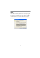
Motherboard User’s Guide Notice: Owing to Microsoft’s certifying schedule is various to every supplier, we might have some drivers not certified yet by Microsoft. Therefore, it might happen under Windows XP that a dialogue box (shown as below) pop out warning you this software has not passed Windows Logo testing to verify its compatibility with Windows XP. Please rest assured that our RD department has already tested and verified these drivers.
Chapter 1: Introduction Chapter 1 Introduction This motherboard has a LGA775 socket for latest Intel Pentium 4/Celeron D processors with Hyper-Threading Technology and Front-Side Bus (FSB) speeds up to 800/533 MHz. Hyper-Threading Technology, designed to take advantage of the multitasking features in Windows XP, gives you the power to do more things at once.
Motherboard User’s Guide • • • • • • • • • Hyper-Threading Technology System Memory Controller Support − Dual-channel (128 bits wide) DDR memory interface − Single-channel (64 bits wide) operation supported − Up to 4 GB system memory − Supports DDR266, DDR333, DDR400 DIMM modules AGP Interface Support − AGP 3.0 with 4X / 8X AGP data transfers and 4X / 8X fast writes, respectively PCI Bus Interface − Supports PCI Revision 2.3 Specifiation at 33 MHz Integrated LAN Controller − WfM 2.0 and IEEE 802.
Chapter 1: Introduction Serial ATA • Four Serial ATA Connectors • Transfer rate exceeding best ATA (~150 MB/s) with scalability to higher rates • Low pin count for both host and devices AC’97 Audio Codec • Compliant with AC’97 2.
Motherboard User’s Guide BIOS Firmware This motherboard uses AMI BIOS that enables users to configure many system features including the following: • Power management • Wake-up alarms • CPU parameters and memory timing • CPU and memory timing The firmware can also be used to set parameters for different processor clock speeds. Dimensions • Micro ATX form factor of 244 x 244 mm Note: Hardware specifications and software items are subject to change without notification.
Chapter 2: Motherboard Installation Chapter 2 Motherboard Installation To install this motherboard in a system, please follow these instructions in this chapter: Identify the motherboard components Install a CPU Install one or more system memory modules Make sure all jumpers and switches are set correctly Install this motherboard in a system chassis (case) Connect any extension brackets or cables to headers/connectors on the motherboard Install peripheral devices and make the appropriate conn
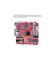
Motherboard User’s Guide Motherboard Components 1 3 4 2 IO PORTS 5 6 22 7 8 9 21 10 11 20 19 12 18 17 16 6 15 14 13
Chapter 2: Motherboard Installation ITEM LABEL COMPONENTS 1 CPU Socket LGA775 Socket for Intel Pentium 4/ Celeron D CPUs 2 PWRFAN Pow er fan connector 3 4 5 CPUFAN IR1 ATX2 CPU Fan connector(4PIN) Infrared header Standard 20-Pin ATX Pow er connector 6 FDD1 Floppy Disk Drive connector 7 IDE1 Primary IDE connector 8 IDE2 Secondary IDE connector 9 DIMM1 DIMM3 DIMM2 184-pin DDR SDRAM sockets (Support Dual-Channel DDR400) 184-pin DDR SDRAM sockets 11 JP1 Clear CMOS jumper 12 SATA1/2 Serial A
Motherboard User’s Guide I/O Ports The illustration below shows a side view of the built-in I/O ports on the motherboard. PS/2 Mouse Use the upper PS/2 port to connect a PS/2 pointing device. PS/2 Keyboard Use the low er PS/2 port to connect a PS/2 keyboard. Parallel Port (LPT1) Use the Parallel port to connect printers or other parallel communications devices. COM1 Use the COM port to connect serial devices such as mice or fax/modems. COM1 is identified by the system as COM1.
Chapter 2: Motherboard Installation Installing the Processor This motherboard has a LGA775 socket for the latest Intel Pentium 4/Celeron D processors. When choosing a processor, consider the performance requirements of the system. Performance is based on the processor design, the clock speed and system bus frequency of the processor, and the quantity of internal cache memory and external cache memory. CPU Installation Procedure Follow these instructions to install the CPU: 1 CPUFAN LGA775 Socket pin1 A.
Motherboard User’s Guide C. Install the CPU on the socket • Orientate CPU package to the socket. Make sure you match triangle marker to pin 1 location. D. Close the load plate • Slightly push down the load plate onto the tongue side, and hook the lever. • CPU is locked completely. E. Apply thermal grease on top of the CPU. F. Fasten the cooling fan supporting base onto the CPU socket on the motherboard. G. Make sure the CPU fan is plugged to the CPU fan connector.
Chapter 2: Motherboard Installation DIMM1--3 Memory Module Installation Procedure These modules can be installed with up to 3 GB system memory. Refer to the following to install the memory module. 1. Push down the latches on both sides of the DIMM socket. 2. Align the memory module with the socket. There is a notch on the DIMM socket that you can install the DIMM module in the correct direction. Match the cutout on the DIMM module with the notch on the DIMM socket. 3.
Motherboard User’s Guide Jumper Settings Connecting two pins with a jumper cap is SHORT; removing a jumper cap from these pins, OPEN. 1 JP1 JP1: Clear CMOS Jumper Use this jumper to clear the contents of the CMOS memory. You may need to clear the CMOS memory if the settings in the Setup Utility are incorrect and prevent your motherboard from operating. To clear the CMOS memory, disconnect all the power cables from the motherboard and then move the jumper cap into the CLEAR setting for a few seconds.
Chapter 2: Motherboard Installation Install the Motherboard Install the motherboard in a system chassis (case). The board is a Micro ATX size motherboard. You can install this motherboard in an ATX case. Make sure your case has an I/O cover plate matching the ports on this motherboard. Install the motherboard in a case. Follow the case manufacturer’s instructions to use the hardware and internal mounting points on the chassis.
Motherboard User’s Guide Connecting Optional Devices Refer to the following for information on connecting the motherboard’s optional devices: 1 IR1 1 AUDIO2 1 1 1 SPK1 USB3 USB2 AUDIO2: Front Panel Audio Header This header allows the user to install auxiliary front-oriented microphone and line-out ports for easier access.
Chapter 2: Motherboard Installation Here is a list of headers USB2/USB3 pin assignments. Pin 1 3 5 7 9 1 2 3 Signal VERG_FP_USBPWR0 USB_FP_P0(-) USB_FP_P0(+) GROUND KEY Pin 2 4 6 8 10 Signal VERG_FP_USBPWR0 USB_FP_P1(-) USB_FP_P1(+) GROUND USB_FP_OC0 Locate the USB2/USB3 header on the motherboard. Plug the bracket cable onto the USB2/USB3 header. Remove a slot cover from one of the expansion slots on the system chassis. Install an extension bracket in the opening.
Motherboard User’s Guide Install Other Devices Install and connect any other devices in the system following the steps below. 1 FDD1 1 1 SATA2 IDE2 IDE1 SATA1 Floppy Disk Drive The motherboard ships with a floppy disk drive cable that can support one or two drives. Drives can be 3.5" or 5.25" wide, with capacities of 360K, 720K, 1.2MB, 1.44MB, or 2.88MB. Install your drives and connect power from the system power supply.
Chapter 2: Motherboard Installation while enabling the storage interface to scale with the growing media rate demands of PC platforms. It provides you a faster transfer rate of 150 MB/s. If you have installed a Serial ATA hard drive, you can connect the Serial ATA cables to the Serial ATA hard drive or the connecter on the motherboard.
Motherboard User’s Guide Expansion Slots This motherboard has one CNR, one AGP Ultra and three 32-bit PCI slots.
Chapter 2: Motherboard Installation Follow the steps below to install an CNR/AGP Ultra/PCI expansion card. 1 Locate the CNR, AGPro and PCI slots on the motherboard. 2 Remove the blanking plate of the slot from the system chassis. 3 Install the edge connector of the expansion card into the slot. Ensure the edge connector is correctly seated in the slot. 4 Secure the metal bracket of the card to the system chassis with a screw.
Motherboard User’s Guide VGA Card Support List for AGP Ultra Slot: VENDOR BUS ATI 4X 8X nVIDIA 4X SIS 8X 8X CHIPSET Radeon 8500 MANUFACTURE ATI RADEON 8500 DDR Radeon 9000 PRO Gigabyte GV-R9000PRO Radeon 9200 ECS R9200LE / 64M Radeon 9200 ECS R9200LE / 128M Radeon 9250 ECS R9250-128T Radeon 9500 Pow er Color ATI 9500 Radeon 9700Pro Pow er Color ATI 9700Pro RIVA TNT2 Model 64 WINFAST S325 TNT M64 GeForce 256 Creative CT6940 GeForce 256 DDR ASUS V6800 DDR GeForce 2 GTS GIGABYTE
Chapter 2: Motherboard Installation Once the AGP card is completely installed under Windows 2000 or Windows XP, the sign like this “? Video Controller” will pop up below the “Device Manager” as the following picture shows. It is normal to see the sign as the onboard VGA card is “Disabled”. Therefore, users don’t have to worry about this point. Note: To install the system with an add-on AGP card, you must make sure to install the driver of add-on AGP card before you install the onboard VGA driver.
Motherboard User’s Guide Dual Monitor In order to enable “Dual Monitor” Function, users must have “Two Monitors”, “Two Graphics Devices” (one is for AGP graphics card, and the other for onboard VGA) and Windows 2000 or Windows XP that supports the Dual Monitor Function. Note: For the Dual Monitor Function, this motherboard only supports “Extended” mode, not “Clone” mode. Users must follow the “Dual Monitor Installation” below or visit our website at : http://www.mercury-pc.com/support.
Chapter 2: Motherboard Installation Step 5: Right click the desktop. Select “Properties” See the picture below: Step 6: Select “Display Properties” Click “Settings” Then the parameters of the two monitors can be adjusted. Dual Monitor Installation (For Windows 2000) If the onboard VGA is first installed, and you would like to use the add-on AGP card. Please follow the installation steps 1--6.
Motherboard User’s Guide Step 3: Remove the Onboard VGA Driver Go to “Control Panel” Choose “Add or Remove Programs” Choose “Intel® Extreme Graphics Driver” Click “Remove” and Restart the computer Note: When you turn on the system, window might report Found New Hardware Wizard, “Video Controller (VGA Compatible)” or “Video Controller”. When you see the Found New Hardware Wizard dialogue box, DO NOT insert any disk in your CD/DVD-ROM before clicking on the “Next” button.
Chapter 3: BIOS Setup Utility Chapter 3 BIOS Setup Utility Introduction The BIOS Setup Utility records settings and information of your computer, such as date and time, the type of hardware installed, and various configuration settings. Your computer applies the information to initialize all the components when booting up and basic functions of coordination between system components. If the Setup Utility configuration is incorrect, it may cause the system to malfunction.
Motherboard User’s Guide You can use cursor arrow keys to highlight anyone of options on the main menu page. Press Enter to select the highlighted option. Press the Escape key to leave the setup utility. Press +/-/ to modify the selected field’s values. Some options on the main menu page lead to tables of items with installed values that you can use cursor arrow keys to highlight one item, and press + and - keys to cycle through alternative values of that item.
Chapter 3: BIOS Setup Utility Advanced Setup Page This page sets up more advanced information about your system. Handle this page with caution. Any changes can affect the operation of your computer. CMOS SETUP UTILITY – Copyright (C) 1985-2004, American Megatrends, Inc.
Motherboard User’s Guide Hyper Threading Technology If your P4 CPU is not HT CPU, this item will be hidden. If your P4 CPU is HT CPU, BIOS will show this item. You can set “Disabled” or “Enabled” to control HT CPU support in O.S. Set “Enabled” to test HT CPU function. Execute Disable Bit It allows the processor to classify areas in memory by where application code can execute and where it cannot.
Chapter 3: BIOS Setup Utility Features Setup Page This page sets up some parameters for peripheral devices connected to the system. CMOS SETUP UTILITY – Copyright (C) 1985-2004, American Megatrends, Inc. Features Setup OnBoard Floppy Controller Serial Port1 Address OnBoard IR Port Parallel Port Address Parallel Port Mode ECP Mode DMA Channel Parallel Port IRQ OnBoard PCI IDE Controller Audio Device Ethernet Device MODEM Device OnBoard USB Function USB Function for DOS USB 2.
Motherboard User’s Guide OnBoard PCI IDE Controller Use this item to enable or disable either or both of the onboard Primary and Secondary IDE channels. There are four options: Disabled, Primary, Secondary and Both. Audio Device This item enables or disables the AC’97 audio chip. Ethernet Device This item enables or disables the onboard Ethernet LAN. MODEM Device This item enables or disables the MC’97 modem chip. OnBoard USB Function Enable this item if you plan to use the USB ports on this motherboard.
Chapter 3: BIOS Setup Utility Power Management Setup Page This page sets some parameters for system power management operation. CMOS SETUP UTILITY – Copyright (C) 1985-2004, American Megatrends, Inc. Power Management Setup ACPI Aware O/S Power Management Suspend Mode Suspend Time Out Resume on RTC Alarm LAN/Ring Power On Keyboard Power On Yes Enabled S1 Disabled Disabled Disabled Disabled Help Item Yes / No ACPI support for Operating System. Yes: If OS supports ACPI. No: If OS does not support ACPI.
Motherboard User’s Guide Ring, or traffic on the network adapter. You must use an ATX power supply in order to use this feature. Keyboard Power On If you enable this item, the system can automatically resume by pressing any keys, power key, or typing in the password on the keyboard. You must use an ATX power supply in order to use this feature. PCI / Plug and Play Setup Page This page sets up some parameters for devices installed on the PCI bus and those utilizing the system plug and play capability.
Chapter 3: BIOS Setup Utility BIOS Security Features Setup Page This page helps you install or change a password. CMOS SETUP UTILITY – Copyright (C) 1985-2004, American Megatrends, Inc. BIOS Security Features Setup Security Settings Help Item Supervisor Password : Not Installed Change Supervisor Password Password Check Press Enter Setup Install or Change the password.
Motherboard User’s Guide Manufacturer/Ratio Status These items show the brand and Locked/Unlocked ratio status of the CPU installed in your system. DRAM Frequency This item shows the frequency of the DRAM in your system. CPU Frequency This item shows the frequency of the CPU installed in your system. CPU Over-clocking Func. This item decides the CPU over-clocking function installed in your system. If the over-clocking fails, please turn off the system power.
Chapter 3: BIOS Setup Utility Load Optimal Defaults If you select this item and press a dialog box appears. If you select [OK], and then press , the Setup Utility loads a set of fail-safe default values. These default values are not very demanding and they should allow your system to function with most kinds of hardware and memory chips. Save Changes and Exit Highlight this item and press to save the changes that you have made in the Setup Utility configuration.
Motherboard User’s Guide Chapter 4 Software & Applications Introduction This chapter describes the contents of the support CD-ROM that comes with the motherboard package. The support CD-ROM contains all useful software, necessary drivers and utility programs to properly run our products. More program information is available in a README file, located in the same directory as the software. To run the support CD, simply insert the CD into your CD-ROM drive.
Chapter 4: Software & Applications The Browse CD button is a standard Windows command that you can check the contents of the disc with the Windows 98 file browsing interface. The Exit button closes the Auto Setup window. To run the program again, reinsert the CD-ROM disc in the drive; or click the CD-ROM driver from the Windows Explorer, and click the Setup icon. The Application button brings up a software menu. It shows the bundled software that this mainboard supports.
Motherboard User’s Guide 3 The support software will automatically install. Once any of the installation procedures start, software is automatically installed in sequence. You need to follow the onscreen instructions, confirm commands and allow the computer to restart as few times as needed to complete installing whatever software you selected. When the process is finished, all the support software will be installed and start working.
Chapter 4: Software & Applications Hyper-Threading CPU While you are in Windows Task Manager, please push down ctrl+Alt Del keys. A dual CPU appears in the CPU Usage History&Device Manager under WinXP. Note: Hyper-Threading Function only works under WINXP Operating System; therefore, disable it under other Operating System.