Mercury 6-5 Stat – Installation & User Guide Mercury 6-5 5 Channel Thermostat Installation Guide For Product: PR0091 Ensure that all power is switched off before installing or maintaining this product Revision 1.
Mercury 6-5 Stat – Installation & User Guide Table of Contents: THE MERCURY RANGE .................................................................................................................................... 3 Description ......................................................................................................................................................... 3 Configuration ................................................................................................................
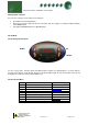
Mercury 6-5 Stat – Installation & User Guide The Mercury Range From Resource Data Management This documentation refers to the Mercury 6-5 - 5 Channel Thermostat Description The Mercury 5 Channel Thermostat has 5 thermostat functions. They can be configured for independent use, where each function is controlled by an individual probe or the controller can be configured to operate selected thermostats from one temperature probe.
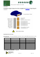
Mercury 6-5 Stat – Installation & User Guide Connections All connections are made to the back of the controller. The diagram below shows the connection detail. Inputs and outputs are assigned according to the chosen configuration. See Specification for further details on connections. ! Do not connect an earth. Input/Output Allocation Tables An over-ride can be achieved by switching in a fixed value resistor in parallel with the probe inputs as shown in the table below.
Mercury 6-5 Stat – Installation & User Guide Setting up the controller Access to the controller can be achieved several ways • • • Through the front mounted buttons Direct access by PC or palm top into the rear comms port. This requires a software package available on the RDM website Through the RDM Data Director or Data Manager.
Mercury 6-5 Stat – Installation & User Guide Recommended set-up method If you are not connecting to a network and want to set up the controller through the buttons we recommend you use the following order from the function menu. rtc. Real time clock (This will automatically synchronise on network systems) a. b. c. d. e. f. g. h. i. j. Use the up or down buttons to scroll through the display until the display reads “rtc” Press enter. The display will show “t-1”.
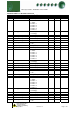
Mercury 6-5 Stat – Installation & User Guide Parameter Tables: Parameter table for 5 Channel Thermostat Number Parameter Range oC ( oF ) P-01 Stat1 Temp Cut-In -49 to 30oC (-56.
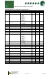
Mercury 6-5 Stat – Installation & User Guide Parameter table for 5 Channel Thermostat Continued....... Number Parameter Range oC ( oF ) P-31 Stat4 Temp Cut-In -49 to 30oC (-56.
Mercury 6-5 Stat – Installation & User Guide Parameter table for 5 Channel Thermostat Continued.......
Mercury 6-5 Stat – Installation & User Guide Network Configuration The final section to set-up is the network address. In all instances, this must be done before the controller is plugged into the site network. The controllers have an auto-initialise function, which will automatically log the device onto the site network. If the wrong address has been entered onto the network, you will have to reset the controller address by setting the address to 00-0, and then re-enter the correct address.
Mercury 6-5 Stat – Installation & User Guide Over-ride Operation The 5 Channel Thermostat can operate either from its internal channel time settings or from a network Data Manager GP Timer channel (P70 sets the mode either local or remote). If the 5 Channel Thermostat is set up to use the remote timing channels it reverts to local mode if network communications are lost for more than 5 minutes.
Mercury 6-5 Stat – Installation & User Guide Normal Operation During normal operation, the controller will display "on". If the 5 Channel Thermostat is on a network and online, the green network LED will be on. If any alarms are generated the red LED will light. The yellow LED has no function and will not light. Frost Detect The frost detect parameter is used to provide heating in an instance where the timer status is off. Each thermostat channel has its own frost detect value that can be configured.
Mercury 6-5 Stat – Installation & User Guide Thermostat Cooling/Heating Operation The diagrams below outline the operation of a channel when it is configured for heating or cooling applications. In this instance the 5 Channel Thermostat’s local timer is on. Cooling Thermostat graph Heating Thermostat graph Ensure that all power is switched off before installing or maintaining this product Revision 1.
Mercury 6-5 Stat – Installation & User Guide Viewing Apart from setting up the controller, you can also view the status of the inputs and outputs. 1. IO. View Inputs / Outputs and States a. From the function menu, select “IO”, press enter b. You can now scroll through the IO tables as set out below. The tables you view will depend on the controller type configuration.
Mercury 6-5 Stat – Installation & User Guide Network Alarms The table below shows the text and associated type number that is sent to the system "front end". The type number is normally used to provide different alarm actions.
Mercury 6-5 Stat – Installation & User Guide Specification General Power requirements: Supply Voltage Range: Supply Frequency: Maximum supply current: Typical supply current: Operating temperature range: Operating Humidity: Storage temperature range: Environmental: Size: Weight: Safety: EMC: Ventilation: Class 2 Insulation: 100 - 240 Vac ±10% 50 - 60 Hz ±10% <1 Amp (With no relay loads) <0.
Mercury 6-5 Stat – Installation & User Guide Inputs: Input resistance: Input type 3.01K Ohms (for PTC or NTC type probes) PT1000 NTC2000 NTC2k25 Comms: RS232 with flow control Ensure that all power is switched off before installing or maintaining this product Revision 1.
Mercury 6-5 Stat – Installation & User Guide Installation: Panel Cut-out: 72mm 17mm 34mm 93mm 2 holes: 3.5mm dia. Fixing: The controller can be fixed either by 2 X M3 screws from the rear or by the plastic retaining device (PR0329), obtainable from RDM. Clearances: The controller must have 5mm clearance above the top and below bottom, and 25mm clearance from the sides. Clearance at the rear is dependant on the wiring.
Mercury 6-5 Stat – Installation & User Guide Wiring: ! Relay 4 and 5 N/O are fed from the supply input Note: Suitable mechanical restraints on the wiring to the controller may be required; dependant on cable types, to prevent undue stress or distortion on the controller connectors.
Mercury 6-5 Stat – Installation & User Guide Fuse: The host equipment must provide a suitable external over-current protection device such as: Fuse: Or MCB: 6.3A, 240 Vac Antisurge (T) HRC conforming to IEC 60127 (Relay 4 & 5 fully loaded) 8A, 240 Vac Type C conforming to BS EN 60898 (Relay 4 & 5 fully loaded) Cleaning: Do not wet the controller when cleaning. Clean the front by wiping with slightly damped lint free cloth.
Mercury 6-5 Stat – Installation & User Guide Revision History Revision Date Changes 1.0 1.1 1.2 27/10/2006 01/03/2007 05/03/2007 First Issue General Tidy Up Removal of over-ride description (for when a channel is configured as a timer). Ensure that all power is switched off before installing or maintaining this product Revision 1.