Contents Before driving Introduction 2 Instrumentation 4 Controls and features 16 Seating and safety restraints 70 Starting and driving Starting 96 Driving 101 Roadside emergencies 118 Servicing Maintenance and care 135 Capacities and specifications 180 Customer assistance 189 Reporting safety defects 204 Index 205 All rights reserved.
Introduction ICONS Indicates a safety alert. Read the following section on Warnings. Indicates vehicle information related to recycling and other environmental concerns will follow. Correct vehicle usage and the authorized disposal of waste cleaning and lubrication materials are significant steps towards protecting the environment. Indicates a message regarding child safety restraints. Refer to Seating and safety restraints for more information.
Introduction INFORMATION ABOUT THIS GUIDE The information found in this guide was in effect at the time of printing. Ford may change the contents without notice and without incurring obligation.
Instrumentation Instrument cluster (pg. 6) Headlamp control (pg. 16) – 40 F H E C SERVICE ENGINE SOON LOW COOLANT Trunk release — sedan only (pg. 53) Parking brake release (pg. 103) Rear window wiper and washer — wagon only (pg. 46) 4 80 THEFT 10 0 40 160 Driver side air bag (pg. 83) Turn signal and wiper/washer control (pg.
Instrumentation Electronic sound system (pg. 29) AM FM 12 AMC w BL RF H Passenger side air bag (pg. 84) M FM BASS TREB VOL PUSH-ON REW EJECT SEEK FF BAL SCAN TUNE 1 3 2 4 w 5 TAPE SIDE 6 FADE TAPE R-DEF OFF VENT LO A/C HI MAX A/C Climate control systems (pg. 18) Gearshift (pg.
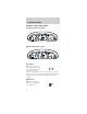
Instrumentation WARNING LIGHTS AND CHIMES Standard instrument cluster – H 30 80 FUEL DOOR> E C SERVICE ENGINE SOON 10 20 0 THEFT km/h180 MPH P R N D 5 D 1 RPMx1000 90 140 6 1 160 0 LOW COOLANT 4 2 120 0 00013 40 3 80 100 60 20 + 50 60 0 1 2 2 70 40 F 100 7 UNLEADED FUEL ONLY 0 110 ABS O/D OFF ! P BRAKE CRUISE Optional instrument cluster F FUEL DOOR> 0 00000 20 10 SERVICE ENGINE SOON LOW COOLANT 3 90 60 C + 100 30 E – 60 70 50 0 0 0 0 80 40 H 10
Instrumentation Safety belt Momentarily illuminates when the ignition is turned to the ON position to remind you to fasten your safety belts. For more information, refer to the Seating and safety restraints chapter. Door ajar Illuminates when the ignition is in the ON or START position and any door is open. Service engine soon Your vehicle is SERVICE ENGINE equipped with a SOON computer that monitors the engine’s emission control system.
Instrumentation Temporary malfunctions may cause your Service Engine Soon light to illuminate. Examples are: 1. The vehicle has run out of fuel. (The engine may misfire or run poorly.) 2. Poor fuel quality or water in the fuel. 3. The fuel cap may not have been properly installed and securely tightened. These temporary malfunctions can be corrected by filling the fuel tank with good quality fuel and/or properly installing and securely tightening the gas cap.
Instrumentation of a tank indicated on the fuel gauge (refer to Fuel gauge in this chapter for more information). The ignition must be in the ON position for this lamp to illuminate. The lamp will also illuminate for several seconds after the ignition is turned to the ON position regardless of the fuel level. Low coolant (if equipped) This lamp will LOW illuminate when the COOLANT engine coolant inside the reservoir is low.
Instrumentation Speed control (if equipped) This light comes on CRUISE when either the SET/ ACCEL or RESUME controls are pressed. It turns off when the speed control OFF control is pressed, the brake is applied or the ignition is turned to the OFF position. Brake system warning Momentarily illuminates ! P when the ignition is turned to the ON BRAKE position, the engine is off and the parking brake is engaged. If the brake warning lamp does not illuminate at this time, seek service immediately.
Instrumentation Air bag readiness Momentarily illuminates when the ignition is turned ON. If the light fails to illuminate, continues to flash or remains on, have the system serviced immediately. Safety belt warning chime Chimes to remind you to fasten your safety belts. For information on the safety belt warning chime, refer to the Seating and safety restraints chapter.
Instrumentation GAUGES Standard instrument cluster gauges – H 30 80 FUEL DOOR> E C 10 SERVICE ENGINE SOON 0 THEFT 160 km/h180 MPH P R N D 5 D 1 RPMx1000 90 140 20 0 LOW COOLANT 4 2 120 0 00013 40 3 80 100 60 20 + 50 60 0 1 2 2 70 40 F 6 1 100 7 UNLEADED FUEL ONLY 0 110 ABS O/D OFF ! P BRAKE CRUISE Optional instrument cluster gauges F FUEL DOOR> 0 00000 10 SERVICE ENGINE SOON LOW COOLANT 2 140 100 MPH THEFT P km/h R N D 2 1 5 6 RPMx1000 1 20 180
Instrumentation • Optional instrument cluster 60 70 50 0 0 0 0 80 40 100 30 90 60 0 00000 20 140 100 20 10 110 180 MPH P km/h 120 R N D 2 1 Tachometer Indicates the engine speed in revolutions per minute. • Standard instrument 3 4 cluster 5 2 RPMx1000 6 1 0 • Optional instrument cluster UNLEADED FUEL ONLY 3 2 4 7 5 RPMx1000 6 1 7 0 PREMIUM UNLEADED FUEL RECOMMENDED 8 Driving with your tachometer pointer in the red zone may damage the engine.
Instrumentation Engine coolant temperature gauge Indicates the temperature of the H engine coolant. At normal operating C temperature, the needle remains within the normal area (the area between the “H” and “C”). If it enters the red section, the engine is overheating. Stop the vehicle as soon as safely possible, switch off the engine immediately and let the engine cool. Refer to Engine coolant in the Maintenance and care chapter. Never remove the coolant reservoir cap while the engine is running or hot.
Instrumentation Fuel gauge Displays approximately how much fuel is in F the fuel tank (when the key is in the ON position). The fuel E gauge may vary slightly when the vehicle is in motion. The ignition should be in the OFF position while the vehicle is being refueled. When the gauge first indicates empty, there is a small amount of reserve fuel in the tank.
Controls and features HEADLAMP CONTROL Rotate the headlamp control to the first position to turn on the parking lamps. Rotate to the second position to also turn on the headlamps. P PANEL AUTO DIM LAMP Daytime running lamps (DRL) (if equipped) Turns the headlamps on with a reduced output. To activate: • the engine must be running and • the headlamp control is in the OFF or Parking lamps position. Always remember to turn on your headlamps at dusk or during inclement weather.
Controls and features Flash to pass Pull toward you to activate and release to deactivate. PANEL DIMMER CONTROL Use to adjust the PANEL P DIM brightness of the instrument panel during headlamp and parklamp operation. • Rotate up to brighten. • Rotate down to dim. • Rotate to full down position to turn off. AUTO LAMP AUTOLAMP CONTROL The autolamp system PANEL AUTO P DIM LAMP provides light sensitive automatic on-off control of the exterior lights normally controlled by the headlamp control.
Controls and features • To turn autolamps on, rotate the control up. The preselected time lapse is adjustable up to approximately three minutes by continuing to rotate the control upward. • To turn autolamps off, rotate the control down until it clicks. REAR WINDOW DEFROSTER Clears the rear window of thin ice and fog. To operate: 1. Turn the ignition to the ON position. 2. Press and release R-DEF the control once to turn on. The light will be lit while the rear window defroster is on. 3.
Controls and features Fan speed control Controls the volume of air circulated in the vehicle. LO HI Temperature control knob Controls the temperature of the airflow inside the vehicle. Mode selector control Controls the direction of the airflow to the inside of the vehicle. The air conditioning compressor will operate in all modes except VENT and . However, the air conditioning will only function if the outside temperature is about 10°C (50°F) or above.
Controls and features • A/C-Uses outside air to cool the vehicle. It is quieter than MAX A/C but not as economical. Airflow will be from the instrument panel registers. • VENT-Distributes outside air through the instrument panel registers. However, the air will not be cooled below the outside temperature because the air conditioning does not operate in this mode. • OFF-Outside air is shut out and the fan will not operate.
Controls and features • -Distributes outside air through the windshield defroster ducts. It can be used to clear ice or fog from the windshield. If the temperature is about 10°C (50°F) or higher, the air conditioner will automatically dehumidify the air to prevent fogging. Operating tips • In humid weather, select before driving. This will prevent your windshield from fogging. After a few minutes, select any desired position.
Controls and features Electronic Automatic Temperature Control (EATC) system (if equipped) — TEMP + — AUTO AUTO F OFF + F-DEF R-DEF OUT SIDE TEMP MAX A/C VENT The EATC system will maintain a selected temperature and automatically control airflow. You can override automatic operation with any of the override controls or the fan speed control.
Controls and features Automatic operation Press AUTO and select the desired temperature. The selected temperature and the word AUTO will appear in the display window. The EATC system will either heat or cool to achieve the selected temperature. The system will automatically determine fan speed, airflow location and if fresh outside air or recirculated air is required. Fan speed remains automatic unless the fan speed control is pressed.
Controls and features For continuous maximum cooling, push the temperature control until 16°C (60°F) is shown in the display window. The EATC will continue maximum cooling (disregarding the displayed temperature) until a warmer temperature is selected by pressing the temperature control. For continuous maximum heating, push the temperature control until 32°C (90°F) is shown in the display window.
Controls and features The display will show and a bar graph to indicate manual fan operation and relative speed. AUTO F FAN • • • To return to automatic fan operation, press AUTO. Manual override controls — TEMP + — AUTO AUTO F OFF + F-DEF TEMP MAX R-DEF OUT SIDE A/C VENT The override controls are located at the bottom of the EATC and allow you to determine where airflow is directed. To return to full automatic control, press AUTO.
Controls and features • MAX A/C-Uses recirculated air to cool the vehicle. The temperature will remain unchanged and air will be cooled based on the selected temperature. To exit, press AUTOMATIC or any other override controls. MAX A/C is noisier than normal A/C but more economical and will cool the inside of the vehicle faster. Airflow is from the instrument panel registers. This mode can also be used to prevent undesirable odors from entering the vehicle.
Controls and features • F- DEF -Distributes outside air through the windshield defroster ducts. It can be used to clear ice or fog from the windshield. If the outside air temperature is about 10°C (50°F) or higher, the air conditioner will automatically dehumidify the air to prevent fogging. • OFF-Outside air is shut out and the fan will not operate. For short periods of time only, use this mode to prevent undesirable odors from entering the vehicle.
Controls and features • Remove any snow, ice or leaves from the air intake area (at the bottom of the windshield). • If your vehicle has been parked with the windows closed during hot weather, the air conditioner will do a much faster job of cooling if you drive for two or three minutes with the windows open. This will force most of the hot, stale air out of the vehicle. Then operate the air conditioner as you would normally.
Controls and features USING YOUR AUDIO SYSTEM AM/FM Stereo/Cassette/Ford MACH Audio System with CD DJ Compatibility AM FM 12 AMC w BL RF H ST M FM BASS TREB VOL PUSH-ON EJECT SEEK DOLBY B ® TAPE CD BAL SCAN TUNE DISC 1-6 SIDE 1-2 SHUFFLE 1 COMP 2 3 4 REW 5 FF FADE 6 Volume/power control Press the control to turn the audio system on or off. VOL PUSH-ON Turn control to raise or lower volume.
Controls and features your preset volume level, turn the audio system off with the power control before switching off the ignition. AM/FM select The AM/FM select control works in radio, tape and CD modes (if equipped). AM FM VOL PUSH-ON AM/FM select in radio mode This control allows you to select AM or FM frequency bands. Press the control to switch between AM, FM1 or FM2 memory preset stations. AM/FM select in tape mode Press this control to stop tape play and begin radio play.
Controls and features Tune adjust for CD mode • Press the to select the previous disc in the CD changer. (Play will begin on the first track of the disc unless the CD changer is in shuffle mode. Refer to Shuffle feature for more information. Hold the control to continue reversing through the disc. • Press to select the next disc in the CD changer. Hold the control to fast-forward through the remaining discs. Seek function The seek function control works in radio, tape or CD mode.
Controls and features Scan function The scan function works in radio, tape or CD mode. SCAN Scan function in radio mode Press the SCAN control to hear a brief sampling of all listenable stations on the frequency band. Press the control again to stop the scan mode. Scan function in tape mode Press the SCAN control to hear a short sampling of all selections on the tape. (The tape scans in a forward direction.
Controls and features SIDE 1-2 COMP SHUFFLE 1 2 3 4 FF REW 6 5 3. Press and hold a memory preset control until the sound returns, indicating the station is held in memory on the control you selected. Bass/treble adjust • The bass adjust control allows you to increase or decrease the audio system’s bass output. BASS TREB BAL FADE • The treble adjust control allows you to increase or decrease the audio system’s treble output.
Controls and features • Speaker sound can be adjusted between the front and rear speakers. BASS TREB BAL FADE Inserting a tape Push only slightly when TAPE CD inserting a cassette tape (with the open edge to the right). A cassette deck loading mechanism pulls the tape in the rest of the way. You can switch from CD to tape play by inserting a tape into the cassette deck.
Controls and features • In CD mode, pressing the REW control for less than three seconds results in slow rewind. Pressing the control for more than three seconds results in fast rewind. Fast forward The fast forward FF control works in tape 6 and CD modes. • In the tape mode, tape direction will automatically reverse when the end of the tape is reached. • In CD mode, pressing the control for less than three seconds results in slow forward action.
Controls and features Compression adjust Compression adjust COMP SHUFFLE 2 brings soft and loud CD 1 passages together for a more consistent listening level. Press the COMP control to activate and deactivate compression adjust. Shuffle feature The shuffle feature COMP SHUFFLE 2 operates in CD mode 1 and plays all tracks on the current disc in random order. If equipped with the CD changer, the shuffle feature continues to the next disc after all tracks are played.
Controls and features CD changer (if equipped) Your CD changer is either located in the trunk or in the right side cargo area storage compartment. Slide the door to access the CD changer magazine. Press to eject the magazine. Make sure only one disc is inserted in each slot. Each disc must be inserted with the label surface upward. Depending on your system, you may insert up to six or ten CDs.
Controls and features The CD magazine may be inserted or ejected with the radio power off. Troubleshooting the CD changer (if equipped) The laser beam used in the compact disc player is harmful to the eyes. Do not attempt to disassemble the case. If sound skips: • You may be traveling on a rough road, playing badly scratched discs or the disc may be dirty. Skipping will not scratch the discs or damage the player.
Controls and features • Do not insert more than one disc into each slot of the CD changer magazine. Cleaning cassette player (if equipped) Clean the tape player head with a cassette cleaning cartridge after ten to twelve hours of play in order to maintain the best sound and operation. Cassette and cassette player care • Use only cassettes that are 90 minutes long or less. • Do not expose tapes to direct sunlight, high humidity, extreme heat or extreme cold.
Controls and features modulation.” Signal modulation is a process radio stations use to increase their strength/volume relative to other stations. • Terrain. Hills, mountains and tall buildings between your vehicle’s antenna and the radio station signal can cause FM reception problems. Static can be caused on AM stations by power lines, electric fences, traffic lights and thunderstorms. Moving away from an interfering structure (out of its “shadow”) returns your reception to normal. • Station overload.
Controls and features 4. ON, all electrical circuits operational. Warning lights illuminated. Key position when driving. 5. START, cranks the engine. Release the key as soon as the engine starts. SPEED CONTROL (IF EQUIPPED) To turn speed control on • Press ON. Vehicle speed cannot be controlled until the vehicle is traveling at or above 48 km/h (30 mph). ON OFF Do not use the speed control in heavy traffic or on roads that are winding, slippery, or unpaved.
Controls and features To set a speed • Press SET/SET ACC/ SET ACCEL. For RESUME speed control to SET operate, the speed ACCEL control must be ON COAST and the vehicle speed must be greater than 48 km/h (30 mph). If you drive up or down a steep hill, your vehicle speed may vary momentarily slower or faster than the set speed. This is normal. Speed control cannot reduce the vehicle speed if it increases above the set speed on a downhill.
Controls and features • Press and release SET/SET ACC/SET ACCEL. Each press will increase the set speed by 1.6 km/h (1 mph) or • Accelerate with your accelerator pedal. When the desired vehicle speed is reached, press and release SET/SET ACC/SET ACCEL. You can accelerate with the accelerator pedal at any time during speed control usage. Releasing the accelerator pedal will return your vehicle to the previously programmed set speed. To set a lower set speed • Press and hold CST/ COAST.
Controls and features Pressing OFF will erase the previously programmed set speed. ON OFF To return to a previously set speed • Press RES/RSM/ RESUME. For RES/ RESUME RSM/RESUME to SET operate, the vehicle ACCEL speed must be faster COAST than 48 km/h (30 mph). Indicator light CRUISE This light comes on when either the SET ACC/SET ACCEL or RES/RSM/RESUME controls are pressed. It turns off when the speed control OFF control is pressed, the brake is applied or the ignition is turned to the OFF position.
Controls and features TURN SIGNAL CONTROL • Push down to activate the left turn signal. • Push up to activate the right turn signal. WINDSHIELD WIPER/WASHER CONTROLS Rotate the windshield wiper control to the desired interval, low or high speed position. The bars of varying length are for intermittent wipers. When in this position rotate the control upward for fast intervals and downward for slow intervals. Push the control on the end of the stalk to activate washer. Push and hold for a longer wash cycle.
Controls and features Rear window wiper and washer (wagon only) The rear wiper control is located under the headlamp controls Press the wiper control to activate the rear wiper. Press again to turn off the wiper. Press the washer control to activate the rear washer. The wiper will come on when the washer control is pressed, if it is not already on. HAZARD FLASHER For information on the hazard flasher control, refer to Hazard flasher in the Roadside emergencies chapter.
Controls and features DOOR OFF ON DOME LAMPS AND MAP LAMPS The front dome lamp is located overhead between the driver and passenger seats. If the vehicle is equipped with a moon roof, the dome lamp is located behind the moon roof. The dome lamp will stay on if the control is moved to the ON position. When the control is in the DOOR position, the lamp will only come on when a door is opened. If the control is moved to the OFF position, the lamp will not come on at all.
Controls and features ILLUMINATED VISOR MIRROR (IF EQUIPPED) To turn on the visor mirror lamps, lift the mirror cover. Adjust the amount of light by sliding the control. MOON ROOF (IF EQUIPPED) Press SLIDE to open and close the moon roof. Press AUTO and release to open completely with one touch. Press UP or DN on the TILT control to tilt the moon roof when closed. TILT SLIDE UP AUTO DN HT LIG LIG HT POWER WINDOWS Press and hold the rocker switches to open and close windows.
Controls and features • Press the bottom portion of the rocker switch to open. AUTO One touch down • Press AUTO completely down and release quickly. The driver’s window will open fully. Depress again to stop window operation. AUTO Window lock The window lock feature allows only the driver to operate the WINDOW LOCK power windows. To lock out all the window controls except for the driver’s press the left side of the control. Press the right side to restore the window controls.
Controls and features POWER DOOR LOCKS (IF EQUIPPED) Press U to unlock all doors and L to lock all doors. U L Central locking/Two step unlocking (if equipped) When unlocking the driver or front passenger door with the key, turn it once toward the front of the vehicle to unlock that door only. Turn the key a second time to unlock all doors. When locking, turn the key toward the back of the vehicle to lock all doors. POWER SIDE VIEW MIRRORS To adjust your mirrors: to adjust the left mirror or 1.
Controls and features Heated outside mirrors (if equipped) Both mirrors are heated automatically to remove ice, mist and fog when the rear window defrost is activated. Do not remove ice from the mirrors with a scraper or attempt to readjust the mirror glass if it is frozen in place. These actions could cause damage to the glass and mirrors. CHILDPROOF DOOR LOCKS When these locks are set, the rear doors cannot be opened from the inside.
Controls and features CENTER CONSOLE Your vehicle may be equipped with a variety of console features. These include: • utility compartment • cupholders • coin holder slots • cellular phone (if equipped) Use only soft cups in the cupholder. Hard objects can injure you in a collision. If your vehicle is equipped with the column shift and a bench seat, it has a center console in the center front seating position. The center console has the same features as the full console.
Controls and features TRUNK REMOTE CONTROL Press the remote trunk release control on the instrument panel to the left of the steering wheel. LIFTGATE (WAGON ONLY) You can open the entire liftgate or just the liftgate window. To open the entire liftgate, pull the release handle hidden under the exterior trim panel just above the license plate. You must lock the liftgate with the key or power lock control; it does not lock automatically. The window locks when the liftgate is locked.
Controls and features CARGO AREA FEATURES Storage compartment Your vehicle comes equipped with a storage compartment in the floor of the cargo area. An additional compartment is in the rear trim panel on the right. Always put the load you are carrying as far forward as possible. Cargo net (if equipped) The cargo net secures lightweight objects in the cargo area. Attach the net to the anchors provided. Do not put more than 22 kg (50 lbs.) in the net.
Controls and features Cargo cover (if equipped) Your vehicle may be equipped with a cargo area shade that covers the luggage compartment of your vehicle. To install the shade: 1. Fasten the cover into the mounting brackets (make sure the cover is right side up). 2. Pull the end of the shade toward you and hook the sides into the notches in the rear trim panels.
Controls and features 2. Wrap the vinyl around the roller tube twice. Tuck the edges of the vinyl inside the end cap with each wrap. 3. Fold the edges of the vinyl towards the center, making sure that the edges clear the end cap slots. Use tape or a rubber band to hold the vinyl to the left side of the tube. 4. Push in the right end cap (marked RH) about 1⁄4 of the total length to disengage the clutch and hold the end cap in while turning the roller tube toward you 14 times. 5. Let go of the right end cap.
Controls and features Unlocking the doors Press this control to unlock the driver’s door. The interior lamps will illuminate. Press the control a second time within five seconds to unlock all doors. Locking the doors Press this control to lock all doors. To confirm all doors are closed and locked, press the control a second time within five seconds. The doors will lock again, the horn will chirp and the lamps will flash.
Controls and features Sounding a panic alarm Press this control to activate the alarm. To deactivate the alarm, press the control again or turn the ignition to ACC or ON. This device complies with part 15 of the FCC rules and with RS-210 of Industry Canada. Operation is subject to the following two conditions: (1) This device may not cause harmful interference, and (2) This device must accept any interference received, including interference that may cause undesired operation.
Controls and features Replacing lost transmitters Take all your vehicle’s transmitters to your dealer if service is required. If you purchase additional transmitters (up to four may be programmed), perform the following procedure: To reprogram the transmitters yourself, place the key in the ignition and turn from OFF to ON eight times in rapid succession (within 10 seconds) ending in ON. After doors lock/unlock, press any control on all transmitters (up to four). When completed, turn the ignition to OFF.
Controls and features To replace the battery: 1. Twist a thin coin between the two halves of the transmitter near the key ring. DO NOT TAKE THE FRONT PART OF THE TRANSMITTER APART. 2. Place the positive (+) side of new battery in the same orientation. Refer to the diagram inside the transmitter unit. 3. Snap the two halves back together. Replacement of the battery will not cause the remote transmitter to become deprogrammed from your vehicle.
Controls and features • Press 7/8 and 9/0 1 2 3 4 5 6 7 8 9 0 controls on the keyless entry pad at the same time to lock the doors (doors opened or closed). • Open a door and press the power door lock control to lock the doors. • Use the door key to lock the doors (doors opened or closed). If a door or the liftgate (wagon) is open, the THEFT system is prearmed and is waiting for the door to close or liftgate to close.
Controls and features Disarming the system You can disarm the system by any of the following actions: • Unlock the doors by using your remote entry transmitter. • Unlock the doors by 1 2 3 4 5 6 7 8 9 0 using your keyless entry pad. • Unlock the doors or liftgate with a key. Turn the key full travel (toward the front of the vehicle) to make sure the alarm disarms. • Turn ignition to ACC or ON. • Press control on the remote entry transmitter. This will disarm the system when the alarm is sounding.
Controls and features Your vehicle has a factory-set 5–digit code that operates the keyless entry system. You can also program your own 5–digit personal entry code. The factory-set code is located: • on the owner’s wallet card in the glove compartment • taped to the computer module When pressing the controls on the keyless entry keypad, press the middle of the controls to ensure a good activation. Programming your own personal entry code 1. Enter the factory-set code (keypad will illuminate when pressed).
Controls and features If you wish to erase your personal code, use the following instructions: Erasing personal code 1. Enter the factory-set code. 2. Press 1/2 within five 1 2 3 4 5 6 7 8 9 0 seconds of step 1. 3. Press the 7/8 and 9/0 controls at the same time within five seconds of step two. The system will now only respond to the factory-set code. Unlocking the doors and releasing the trunk with the keyless entry system The driver’s door must be unlocked before any other.
Controls and features Autolock Autolock is a feature that will automatically lock all doors when: • all vehicle doors, liftgate and liftgate window are fully closed • the ignition key is in the ON position • you shift into or through R (Reverse) • the brake pedal is released The autolock feature repeats when: • any door is opened and then closed • the brake pedal is released Deactivating autolock Before following the activation or deactivation procedures, make sure that the ignition is OFF and all vehicle
Controls and features 3. Turn the ignition key from RUN/ACC to OFF. 4. Press the power door UNLOCK control three times. 5. Turn the ignition key from OFF to RUN/ACC. A horn chirp indicates the enable/disable feature is entered. 6. Press the power door UNLOCK control one time. 7. Press the power door LOCK control to toggle the Autolock/Relock state. You will receive a horn chirp followed by either a long honk, autolock/relock is enabled, or no honk, autolock/relock is disabled. 8. Turn ignition to OFF.
Controls and features problem if they are too close to the key when starting the engine. If a problem occurs, turn ignition off and restart the engine with all other objects on the key ring held away from the SecuriLocky ignition key. Spare SecuriLocky keys can be purchased from your dealership and programmed to your SecuriLocky passive anti-theft system. Refer to Programming spare SecuriLocky keys for more information.
Controls and features not available (one or both of your original keys were lost or stolen), you must bring your vehicle to your dealership to have the spare SecuriLocky key(s) programmed. Procedure to program spare SecuriLockY keys to your vehicle New SecuriLocky keys must have the correct mechanical key cut for your vehicle. Conventional (non-SecuriLocky) keys cannot be programmed to your vehicle.
Controls and features If the programming procedure was successful, the new SecuriLocky key(s) will start the vehicle’s engine. The theft indicator (located on the instrument cluster) will light for three seconds and then go out. If the programming procedure was not successful, the new SecuriLocky key(s) will not operate the vehicle’s engine. The theft indicator will flash on and off. Wait at least one minute and then repeat the procedure from step 1.
Seating and safety restraints SEATING Head restraints Your vehicle’s seats may be equipped with head restraints which are vertically adjustable. The purpose of these head restraints is to help limit head motion in the event of a rear collision. To properly adjust your head restraints, lift the head restraint so that it is located directly behind your head or as close to that position as possible. Refer to the following to raise and lower the head restraints.
Seating and safety restraints Lift handle to move seat forward or backward. Pull lever up to adjust seatback. Adjusting the front power seat (if equipped) Never adjust the driver’s seat or seatback when the vehicle is moving. Do not pile cargo higher than the seatbacks to avoid injuring people in a collision or sudden stop. Always drive and ride with your seatback upright and the lap belt snug and low across the hips. Press to raise or lower the front portion of the seat cushion.
Seating and safety restraints Press to raise or lower the rear portion of the seat cushion. Press the control to move the seat forward, backward, up or down. Using the power lumbar support (if equipped) The power lumbar control is located on the outboard side of the seat. Press one side of the control to adjust firmness. Press the other side of the control to adjust softness.
Seating and safety restraints 3rd seat (wagon only) The third seat faces the rear of the vehicle. For height and weight limits, see the label on the seat cushion. When the seat is down, the back of your wagon has a flat surface for carrying cargo. To open up the seat: 1. Unlock the floor panel with the key, then use the handle to fold the floor panel toward the front of the car. 2. Remove the cargo cover. The cargo cover must be removed or the seatback will not latch in the upright position. 3.
Seating and safety restraints SAFETY RESTRAINTS Safety restraints precautions Always drive and ride with your seatback upright and the lap belt snug and low across the hips. To prevent the risk of injury, make sure children sit where they can be properly restrained. Never let a passenger hold a child on his or her lap while the vehicle is moving. The passenger cannot protect the child from injury in a collision.
Seating and safety restraints Each seating position in your vehicle has a specific safety belt assembly which is made up of one buckle and one tongue that are designed to be used as a pair. 1) Use the shoulder belt on the outside shoulder only. Never wear the shoulder belt under the arm. 2) Never swing the safety belt around your neck over the inside shoulder. 3) Never use a single belt for more than one person. Combination lap and shoulder belts 1.
Seating and safety restraints suddenly or turns a corner sharply, or the vehicle receives an impact of 8 km/h (5 mph) or more, the combination safety belts will lock to help reduce forward movement of the driver and passengers. Automatic locking mode In this mode, the shoulder belt is automatically pre-locked. The belt will still retract to remove any slack in the shoulder belt. The automatic locking mode is not available on the driver safety belt.
Seating and safety restraints • Allow the belt to retract. As the belt retracts, you will hear a clicking sound. This indicates the safety belt is now in the automatic locking mode. How to disengage the automatic locking mode Disconnect the combination lap/shoulder belt and allow it to retract completely to disengage the automatic locking mode and activate the vehicle sensitive (emergency) locking mode.
Seating and safety restraints Failure to replace the Belt and Retractor assembly could increase the risk of injury in collisions. Front safety belt height adjustment Your vehicle has safety belt height adjustments for the driver and front passenger. Adjust the height of the shoulder belt so the belt rests across the middle of your shoulder. To lower the shoulder belt height, push the button and slide the height control down. To raise the height of the shoulder belt, slide the height adjuster up.
Seating and safety restraints To attach the shoulder belt to the lap belt, pull the shoulder belt out from the retractor in the seatback and insert into the lap belt connecting pin into the wide end of the key slot on the shoulder belt. Pull the connecting pin into the narrow end of the key slot until you hear a snap and feel it latch. Make sure the shoulder belt is securely fastened to the lap belt by pulling up on the shoulder belt.
Seating and safety restraints Shorten and fasten the belt when not in use. Safety belts for rear-facing occupants (wagon only) Never use child safety seats in the third seat of a wagon. Your vehicle is equipped with safety belts containing an adjust tongue at the rear-facing seating positions.
Seating and safety restraints The lap belts should fit snugly and as low as possible around the hips, not around the waist. Front and rear seat occupants, including pregnant women, should wear safety belts for optimum protection in an accident. Each seating position in your vehicle has a specific safety belt assembly which is made up of one buckle and one tongue that are designed to be used as a pair. 1) Use the shoulder belt on the outside shoulder only. Never wear the shoulder belt under the arm.
Seating and safety restraints Safety belt extension assembly If the safety belt assembly is too short, even when fully extended, 20 cm (8 inches) can be added to the safety belt assembly by adding a safety belt extension assembly (part number 611C22). Safety belt extension assemblies can be obtained from your dealer at no cost. Use only extensions manufactured by the same supplier as the safety belt. Manufacturer identification is located at the end of the webbing on the label.
Seating and safety restraints Safety belt maintenance Inspect the safety belt systems periodically to make sure they work properly and are not damaged. Inspect the safety belts to make sure there are no nicks, wears or cuts, replacing if necessary.
Seating and safety restraints Important supplemental restraint system (SRS) precautions The supplemental restraint system is designed to work with the safety belt to help protect the driver and right front passenger from certain upper body injuries. Air bags DO NOT inflate slowly or gently and the risk of injury from a deploying air bag is greatest close to the trim covering the air bag module.
Seating and safety restraints Do not put anything on or over the air bag module. Placing objects on or over the air bag inflation area may cause those objects to be propelled by the air bag into your face and torso causing serious injury. Do not attempt to service, repair, or modify the Air Bag Supplemental Restraint System or its fuses. See your Ford or Lincoln-Mercury dealer. Children and air bags For additional important safety information, read all information on safety restraints in this guide.
Seating and safety restraints How does the air bag supplemental restraint system work? The air bag SRS is designed to activate when the vehicle sustains sufficient longitudinal deceleration sufficient to cause the sensors to close an electrical circuit that initiates air bag inflation. The fact that the air bags did not inflate in a collision does not mean that something is wrong with the system. Rather, it means the forces were not of the type sufficient to cause activation.
Seating and safety restraints there is the risk of death or serious injuries such as fractures, facial and eye injuries or internal injuries, particularly to occupants who are not properly restrained or are otherwise out of position at the time of air bag deployment. Thus, it is extremely important that occupants be properly restrained as far away from the air bag module as possible while maintaining vehicle control. Several air bag system components get hot after inflation.
Seating and safety restraints A difficulty with the system is indicated by one or more of the following: • The readiness light will either flash or stay lit. • The readiness light will not illuminate immediately after ignition is turned on. • A series of five beeps will be heard. The tone pattern will repeat periodically until the problem and light are repaired. If any of these things happen, even intermittently, have the SRS serviced at your dealership or by a qualified technician immediately.
Seating and safety restraints Never let a passenger hold a child on his or her lap while the vehicle is moving. The passenger cannot protect the child from injury in a collision. Always follow the instructions and warnings that come with any infant or child restraint you might use. When possible, place children in the rear seat of your vehicle. Accident statistics suggest that children are safer when properly restrained in the rear seating positions than in the front seating position.
Seating and safety restraints seats raise the child and provide a shorter, firmer seating cushion that encourages safer seating posture and better fit of lap and shoulder belts on the child. A belt-positioning booster should be used if the shoulder belt rests in front of the child’s face or neck, or if the lap belt does not fit snugly on both thighs, or if the thighs are too short to let the child sit all the way back on the seat cushion when the lower legs hang over the edge of the seat cushion.
Seating and safety restraints When installing a child safety seat: • Review and follow the information presented in the Air Bag Supplemental Restraint System section in this chapter. • Use the correct safety belt buckle for that seating position. • Insert the belt tongue into the proper buckle until you hear a snap and feel it latch. Make sure the tongue is securely fastened in the buckle.
Seating and safety restraints Installing child safety seats in combination lap and shoulder belt seating positions 1. Position the child safety seat in a seat with a combination lap and shoulder belt. An air bag can kill or injure a child in a child seat. If you must use a forward-facing child seat in the front seat, move seat all the way back. Children 12 and under should be properly restrained in the rear seat whenever possible. 2.
Seating and safety restraints 4. Insert the belt tongue into the proper buckle (the buckle closest to the direction the tongue is coming from) for that seating position until you hear a snap and feel the latch engage. Make sure the tongue is latched securely by pulling on it. 5. To put the retractor in the automatic locking mode, grasp the shoulder portion of the belt and pull downward until all of the belt is extracted and a click is heard. 6. Allow the belt to retract.
Seating and safety restraints 10. Try to pull the belt out of the retractor to make sure the retractor is in the automatic locking mode (you should not be able to pull more belt out). If the retractor is not locked, unbuckle the belt and repeat steps two through nine. Check to make sure the child seat is properly secured before each use. Installing child safety seats in the lap belt seating positions 1. Lengthen the lap belt.
Seating and safety restraints Tether anchorage hardware Attachment holes (at each rear outboard seating position) have been provided in your vehicle to attach anchor hardware, if desired. Tether anchorage hardware kits (part number 613D74) including instructions, may be obtained at no charge from any Ford or Lincoln-Mercury dealer. All vehicles built for sale in Canada include a tether anchor hardware kit. Be sure to follow the child safety seat manufacturer’s instructions.
Starting PREPARING TO START YOUR VEHICLE Engine starting is controlled by the ignition system. This system meets all Canadian Interference-Causing Equipment standard requirements regulating the impulse electrical field strength of radio noise. When starting a fuel-injected engine, avoid pressing the accelerator before or during starting. Only use the accelerator when you have difficulty starting the engine. For more information on starting the vehicle, refer to Starting the engine in this chapter.
Starting Important safety precautions A computer system controls the engine’s idle revolutions per minute (RPM). When the engine starts, the idle RPM runs faster to warm the engine. If the engine idle speed does not slow down automatically, have the vehicle checked. Do not allow the vehicle to idle for more than ten minutes at the higher engine RPM. Before starting the vehicle: 1. Make sure all vehicle occupants have buckled their safety belts.
Starting F 0 00000 20 C SERVICE ENGINE SOON 10 THEFT 4 RPMx1000 100 6 1 180 P 5 2 140 20 MPH LOW COOLANT 3 90 60 E + 100 30 FUEL DOOR> – 60 70 50 0 0 0 0 80 40 H km/h 110 120 R N D 2 1 0 O/D OFF UNLEADED FUEL ONLY ABS 7 ! P BRAKE CRUISE Make sure the corresponding lights illuminate briefly. If a light fails to illuminate, have the vehicle serviced. • If the driver’s safety belt is fastened, the light may not illuminate. STARTING THE ENGINE 1.
Starting Using the engine block heater (if equipped) An engine block heater warms the engine coolant, which improves starting, warms up the engine faster and allows the heater-defroster system to respond quickly. Use of an engine block heater is strongly recommended if you live in a region where temperatures reach -23°C (-10°F) or below. For best results, plug the heater in at least three hours before starting the vehicle.
Starting Engine exhaust, some of its constituents, and certain vehicle components contain or emit chemicals known to the State of California to cause cancer, and birth defects or other reproductive harm. Important ventilating information If the engine is idling while the vehicle is stopped in an open area for long periods of time, open the windows at least 2.5 cm (one inch). Adjust the heating or air conditioning (if equipped) to bring in fresh air.
Driving BRAKES Your service brakes are self-adjusting. Refer to the scheduled maintenance guide for scheduled maintenance. Occasional brake noise is normal and often does not indicate a performance concern with the vehicle’s brake system. In normal operation, automotive brake systems may emit occasional or intermittent squeal or groan noises when the brakes are applied.
Driving The ABS operates by detecting the onset of wheel lockup during brake applications and compensating for this tendency. The wheels are prevented from locking even when the brakes are firmly applied. The accompanying illustration depicts the advantage of an ABS equipped vehicle (on bottom) to a non-ABS equipped vehicle (on top) during hard braking with loss of front braking traction.
Driving • The Anti-Lock system does not decrease the time necessary to apply the brakes or always reduce stopping distance. Always leave enough room between your vehicle and the vehicle in front of you to stop. • We recommend that you familiarize yourself with this braking technique. However, avoid taking any unnecessary risks. Parking brake Apply the parking brake whenever the vehicle is parked. To set the parking brake, press the parking brake pedal down until the pedal stops.
Driving Pull the release lever to release the brake. Driving with the parking brake on will cause the brakes to wear out quickly and reduce fuel economy. STEERING Your vehicle is equipped with power steering. Power steering uses energy from the engine to help steer the vehicle. To prevent damage to the power steering pump: • Never hold the steering wheel to the extreme right or the extreme left for more than a few seconds when the engine is running.
Driving AUTOMATIC TRANSAXLE OPERATION Brake-shift interlock This vehicle is equipped with a brake-shift interlock feature that prevents the gearshift from being moved from P (Park) unless the brake pedal is depressed. If you cannot move the gearshift out of P (Park) with the brake pedal depressed: 1. Apply the parking brake, turn ignition key to LOCK, then remove the key. 2. Insert the key and turn it to OFF. Apply the brake pedal and shift to N (Neutral). 3. Start the vehicle.
Driving If the parking brake is fully released, but the brake warning lamp remains illuminated, the brakes may not be working properly. See your dealer or a qualified service technician. Driving with an automatic overdrive transaxle Your automatic overdrive transaxle provides fully automatic operation in (Overdrive) either or D (Drive). Driving with the shift selector (Overdrive) gives in the best fuel economy for normal driving conditions. For manual control start in 1 (First) and then shift manually.
Driving Understanding gearshift positions P (Park) Always come to a complete stop before shifting into P (Park). Make sure the gearshift is securely latched in P (Park). This locks the transaxle and prevent the front wheels from rotating. P R N D D 1 Always set the parking brake fully and make sure the gearshift is securely latched in P (Park). Never leave your vehicle unattended while it is running. R (Reverse) With the gearshift in R (Reverse), the vehicle will move backward.
Driving N (Neutral) With the gearshift in the N (Neutral) position, the vehicle can be started and is free to roll. Hold the brake pedal down while in this position. P R N D D 1 (Overdrive) The (Overdrive) P R N D D 1 position is the normal driving position for an automatic overdrive transaxle. It works the same way as D (Drive) but shifts to a fourth gear — an overdrive gear — when your vehicle cruises at a constant speed for any length of time.
Driving When to use D (Drive) The D (Drive) position eliminates the needless shifting back and forth between third and fourth gears that your vehicle may do when driving on hilly terrain. It also gives more engine braking than overdrive to slow your vehicle on downgrades. 1 (First) Use 1 (First) for when added engine braking is desired when descending steep hills. The automatic transaxle will shift to the proper gear to ascend any grade without any need to shift to 1 (First).
Driving VEHICLE LOADING Before loading a vehicle, familiarize yourself with the following terms: • Base Curb Weight : Weight of the vehicle including any standard equipment, fluids, lubricants, etc. It does not include passengers or aftermarket equipment. • Payload : Combined maximum allowable weight of cargo, passengers and optional equipment. The payload equals the gross vehicle weight rating minus base curb weight. • GVW (Gross Vehicle Weight) : Base curb weight plus payload weight.
Driving • Maximum Trailer Weight : maximum weight of a trailer the loaded vehicle (including passengers and cargo) is permitted to tow. It is determined by subtracting the weight of the loaded trailer towing vehicle from the GCWR for the towing vehicle. • Trailer Weight Range : Specified weight range that the trailer must fall within that ranges from zero to the maximum trailer weight rating. Remember to figure in the tongue load of your loaded trailer when figuring the total weight.
Driving Always ensure that the weight of passengers, cargo and equipment being carried is within the weight limitations that have been established for your vehicle including both Gross Vehicle Weight and Front and Rear Gross Axle Weight Rating limits. Under no circumstance should these limitations be exceeded. Exceeding any vehicle weight rating limitation could result in serious damage to the vehicle and/or personal injury.
Driving Towing a trailer places an additional load on your vehicle’s engine, transaxle, brakes, tires and suspension. Inspect these components carefully after towing. The amount of weight that you can tow depends on the type of engine in your vehicle. See the following charts: Model Sedan Wagon 3.0L 2-Valve Vulcan Engine Passenger Luggage Max Trailer Load-#/kg Load-kg Wt.-kg (lbs.) (lbs.) (lbs.
Driving Do not exceed the GVWR or the GAWR specified on the Safety Compliance Certification Label. Towing trailers beyond the maximum recommended gross trailer weight exceeds the limit of the vehicle and could result in engine damage, transaxle damage, structural damage, loss of control, and personal injury. Preparing to tow Use the proper equipment for towing a trailer, and make sure it is properly attached to your vehicle. See your dealer or a reliable trailer dealer if you require assistance.
Driving Do not connect a trailer’s hydraulic brake system directly to your vehicle’s brake system. Your vehicle may not have enough braking power and your chances of having a collision greatly increase. The braking system of the tow vehicle is rated for operation at the GVWR not GCWR. Trailer lamps Trailer lamps are required on most towed vehicles. Make sure your trailer lamps conform to local and Federal regulations.
Driving Trailer towing tips • Practice turning, stopping and backing up in an area before starting on a trip to get the feel of the vehicle trailer combination. When turning, make wider turns so the trailer wheels will clear curbs and other obstacles. • Allow more distance for stopping with a trailer attached. • The trailer tongue weight should be 10% of the loaded trailer weight. • After you have traveled 80 km (50 miles), thoroughly check your hitch, electrical connections and trailer wheel lug nuts.
Driving Never use a tow bar that attaches to the bumper when you tow your vehicle. This could damage the bumper and cause an accident. LUGGAGE RACK (IF EQUIPPED) The rear crossbar can be adjusted to fit the item being carried. The front crossbar does not move. Do not load more than 44 kg (100 lbs.) on the luggage rack. To adjust cross-bar position: 1. Loosen the thumbwheel at both ends of the cross-bar. 2. Slide the cross-bar to the desired location. 3. Tighten the thumbwheel at both ends of the cross-bar.
Roadside emergencies HAZARD FLASHER Use only in an emergency to warn traffic of vehicle breakdown, approaching danger, etc. The hazard flashers can be operated when the ignition is off. • The hazard lights control is located on top of the steering column. • Depress hazard lights control to activate all hazard flashers simultaneously. • Depress control again to turn the flashers off.
Roadside emergencies If your vehicle is a sedan, the Resetting the fuel shut-off switch is located on the right side of the trunk behind the trunk liner. If your vehicle is a wagon, the Resetting the fuel shut-off switch is located behind the service panel on the right side of the cargo area. FUSES AND RELAYS Fuses If electrical components in the vehicle are not 15 working, a fuse may have blown. Blown fuses are identified by a broken wire within the fuse.
Roadside emergencies Standard fuse amperage rating and color COLOR Fuse Rating 2A 3A 4A 5A 7.
15A HIGH BEAM 15A 10A DIAGNOS DECKLID RELEASE 5A 20A CIGAR MIRRORS ANTENNA 30A 5A FRONT HEAD LP WIPERS ILLUM 5A 5A AIR BAG LIGHT OUT MOD 20A 10A EEC ABS IGN COIL 5A 15A SHIFT BK LPS INTLOCK AC 5A INSTR ILLUM 15A HAZARD LAMPS INTERIOR LAMP RELAY DRIVER UNLOCK RELAY BATTERY SAVER RELAY DRIVER WINDOW RELAY 5A TAIL LAMPS 10A BATTERY SAVER 5A WIPER & VAPS 15A REAR WIPER 10A TURN SIGNAL 5A AIR BAG ALT LPS 10A STARTER RELAY 10A LT LOW BEAM 5A RADIO MEMORY 20A RHD PWR LKS 5A GAUGES WRN LPS 5A RADIO MUTE 10A RT
Roadside emergencies Fuse/ Fuse Description Relay Amp Location Rating 14 5A Semi-Active Ride Control Module 15 10A Multifunction Switch (Turn Signal) 16 — Not Used 17 30A Front Wiper/Washer 18 5A Headlamp Switch 19 15A Rear Wiper/Washer 20 5A ICP, RAP, Phone, GEM 21 20A Cigar Lighter 22 5A Power Mirrors, Power Antenna, Luggage Compartment Lamp, Autolamp 23 5A GEM, RAP, PATS 24 5A ICP, RCC, Speedometer 25 10A Data Link Connector (DLC) 26 15A Luggage Compartment 27 10A Battery Saver Relay 28 15A Speed Control
Roadside emergencies Power distribution box The power distribution box is located in the engine compartment. The power distribution box contains highcurrent fuses that protect your vehicle’s main electrical systems from overloads. Always disconnect the battery before servicing high current fuses. Always replace the cover to the Power Distribution Box before reconnecting the battery or refilling fluid reservoirs.
Roadside emergencies 34 28 17 21 24 16 20 23 15 19 27 18 33 13 22 14 7 9 5 11 8 3 12 6 10 4 2 MEGA-FUSE 30 25 29 32 26 31 175A 1 The high-current fuses are coded as follows. Fuse/ Relay Location 1 2 3 4 124 5 6 7 8 Fuse Amp Rating 40A** 30A** 40A** 30A C.B.
Roadside emergencies Fuse/ Fuse Description Relay Amp Location Rating 18 30A* Anti-Lock Brake Module 19 15A* Horn Relay, Powertrain Control Module (PCM) 20 15A* Headlamp Switch, Autolamp Park Relay 21 — Not Used 22 30A* Autolamps Relay, Multifunction Switch, Headlamp Switch 23 — Blower Motor Relay 24 — Starter Relay 25 — A/C Clutch Relay 26 30A* Generator 27 10A* A/C Clutch Relay 28 15A* Heated Oxygen Sensors, Canister Vent 29 — Fuel Pump Relay 30 — PCM Relay 31 — Low Speed Cooling Fan Relay 32 — PCM Diode
Roadside emergencies CHANGING THE TIRES If you get a flat tire while driving, do not apply the brake heavily. Instead, gradually decrease your speed. Hold the steering wheel firmly and slowly move to a safe place on the side of the road. Temporary spare tire information The temporary spare tire for your vehicle is labeled as such. It is smaller than a regular tire and is designed for emergency use only.
Roadside emergencies When one of the front wheels is off the ground, the transaxle alone will not prevent the vehicle from moving or slipping off the jack, even if the vehicle is in P (Park). To prevent the vehicle from moving when you change a tire, be sure the parking brake is set, then block (in both directions) the wheel that is diagonally opposite (other side and end of the vehicle) to the tire being changed. If the vehicle slips off the jack, you or someone else could be seriously injured. 2.
Roadside emergencies 3. Remove the center ornament or wheel cover from the wheel with the tapered end of the wheel nut wrench that came with your vehicle. Insert and twist the handle, then pry against the wheel. 4. Loosen each wheel lug nut one-half turn counterclockwise but do not remove them until the wheel is raised off the ground. 5. Put the jack in the jack notch next to the door of the tire you are changing. Turn the jack handle clockwise until the wheel is completely off the ground. 6.
Roadside emergencies 10. Return the flat tire, jack and lug wrench to their proper storage locations. Make sure the jack is fastened so it does not rattle when you drive. 11. Unblock the wheels. JUMP STARTING YOUR VEHICLE The gases around the battery can explode if exposed to flames, sparks, or lit cigarettes. An explosion could result in injury or vehicle damage. Do not push start your vehicle. You could damage the catalytic converter.
Roadside emergencies 4. Check all battery terminals and remove any excessive corrosion before you attach the battery cables. Ensure that vent caps are tight and level. 5. Turn the heater fan on in both vehicles to protect any electrical surges. Turn all other accessories off. Connecting the jumper cables, 3.0L Vulcan and 3.0L Duratec engines + + – – 1. Connect the positive (+) booster cable to the positive (+) terminal of the discharged battery.
Roadside emergencies + + – – 3. Connect the negative (-) cable to the negative (-) terminal of the assisting battery. + + – – 4. Make the final connection of the negative (-) cable. For the 3.0L Vulcan, make the connection to an exposed metal part of the stalled vehicle’s engine, away from the battery and the carburetor/fuel injection system. For the 3.0L Duratec, make the connection to the hood latch of the disabled engine, away from the battery and the carburetor/fuel injection system.
Roadside emergencies 5. Be sure that the cables are clear of fan blades, belts and other moving parts of both engines. Jump starting 1. Start the engine of the booster vehicle and run the engine at moderately increased speed. 2. Start the engine of the disabled vehicle. 3. Once the disabled vehicle has been started, run both engines for a further three minutes before disconnecting the jumper cables. Removing the jumper cables, 3.0L Vulcan and 3.
Roadside emergencies + + – – 3. Remove the jumper cable from the positive (+) terminal of the booster vehicle’s battery. + + – – 4. Remove the jumper cable from the positive (+) terminal of the disabled vehicle’s battery. After the disabled vehicle has been started and the jumper cables removed, allow it to idle for several minutes so the engine computer can relearn its idle conditions.
Roadside emergencies WRECKER TOWING If you need to have your vehicle towed, contact a professional towing service or, if you are a member, your roadside assistance center. It is recommended that your vehicle be towed with a wheel lift or flatbed equipment. Do not tow with a slingbelt. Ford Motor Company has not approved a slingbelt towing procedure. Ford Motor Company provides a towing manual for all authorized tow truck operators.
Maintenance and care SERVICE RECOMMENDATIONS To help you service your vehicle: • We highlight do-it-yourself items in the engine compartment for easy location. • We provide a Scheduled Maintenance Guide which makes tracking routine service easy. If your vehicle requires professional service, your dealership can provide necessary parts and service. Check your “Warranty Guide” to find out which parts and services are covered.
Maintenance and care 3. Block the wheels to prevent the vehicle from moving unexpectedly. Working with the engine on 1. Set the parking brake and ensure the gearshift is securely latched in P (Park). 2. Block the wheels to prevent the vehicle from moving unexpectedly. Do not start your engine with the air cleaner removed and do not remove it while the engine is running. OPENING THE HOOD 1. Inside the vehicle, pull the hood release handle located under the bottom of the instrument panel. 2.
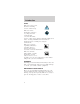
Maintenance and care IDENTIFYING COMPONENTS IN THE ENGINE COMPARTMENT 3.0L V6 Vulcan engine 1 2 9 8 3 7 1. 2. 3. 4. 5. 6. 7. 8. 9.
Maintenance and care 3.0L V6 Duratec engine 8 1 9 2 3 4 7 6 5 1. 2. 3. 4. 5. 6. 7. 8. 9. Automatic transmission fluid dipstick Brake fluid reservoir Air filter assembly Battery Engine oil filler cap Engine oil dipstick Engine coolant reservoir Windshield washer fluid reservoir Power steering fluid reservoir ENGINE OIL Checking the engine oil Refer to the Scheduled Maintenance Guide for the appropriate intervals for checking the engine oil. 1. Make sure the vehicle is on level ground. 2.
Maintenance and care 3. Set the parking brake and ensure the gearshift is securely latched in P. 4. Open the hood. Protect yourself from engine heat. 5. Locate and carefully remove the engine oil indicator (dipstick). ADD 1 QT MIN FULL MAX 6. Wipe the indicator clean. Insert the indicator fully, then remove it again. • If the oil level is between the ADD and FULL marks or between the MIN and MAX marks (depending on application), the oil level is acceptable. DO NOT ADD OIL.
Maintenance and care Adding engine oil 1. Check the engine oil. For instructions, refer to Checking the engine oil in this chapter. 2. If the engine oil level is not within the normal range, add only certified engine oil of the recommended viscosity. Remove the engine oil filler cap and use a funnel to pour the engine oil into the opening. 3. Recheck the engine oil level. Make sure the oil level is not above the F in FULL mark on the dipstick.
Maintenance and care It is recommended you use the appropriate Motorcraft oil filter (or another brand meeting Ford specifications) for your engine application. BRAKE FLUID Checking and adding brake fluid Brake fluid should be checked and refilled as needed. Refer to the Scheduled Maintenance Guide for the service interval schedules: 1. Clean the reservoir cap before removal to prevent dirt or water from entering the reservoir. 2. Visually inspect the fluid level. 3.
Maintenance and care Do not let the reservoir for the master cylinder run dry. This may cause the brakes to fail. WINDSHIELD WASHER FLUID Checking and adding washer fluid Check the washer fluid whenever you stop for fuel. The reservoir is highlighted with a symbol. If the level is low, add enough fluid to fill the reservoir. In very cold weather, do not fill the reservoir all the way. Do not put engine coolant in the container for the windshield washer fluid.
Maintenance and care ENGINE COOLANT Check the level of the engine coolant in the reservoir. Refer to the Scheduled Maintenance Guide for service interval schedules. Be sure to read and understand Precautions when servicing your vehicle in this chapter. If the engine coolant has not been checked at the recommended interval, the engine coolant reservoir may become empty. If this occurs, add engine coolant to the reservoir.
Maintenance and care When the engine is cool, add a 50/50 mixture of engine coolant and water to the engine coolant reservoir. Plain water may be added in an emergency, but you MUST replace it with a 50/50 mixture of coolant and distilled water as soon as possible. Check the coolant level in the coolant reservoir the next few times you drive the vehicle. If necessary, add enough of a 50/50 mixture of coolant and water to bring the liquid level into the cold fill range on the reservoir.
Maintenance and care Do not use alcohol or methanol antifreeze or any engine coolants mixed with alcohol or methanol antifreeze. Do not use supplemental coolant additives in your vehicle. These additives may harm your engine cooling system. The use of an improper coolant may void the warranty of your vehicle’s engine cooling system. Recycled engine coolant Ford Motor Company recommends that Ford and Lincoln-Mercury dealers use recycled engine coolant produced by Ford-approved processes.
Maintenance and care CHECKING AND ADDING POWER STEERING FLUID Check the power steering fluid. Refer to the Scheduled Maintenance Guide for the service interval schedules. If adding fluid is necessary, use only MERCONt ATF. 1. Start the engine and let it run until it reaches normal operating temperature (the engine coolant temperature gauge indicator will be near the center of the normal area between H and C). 2. While the engine idles, turn the steering wheel left and right several times. 3.
Maintenance and care 3.0L Duratec engine 4. Check the fluid level in the reservoir. It should be between the MIN and MAX lines. Do not add fluid if the level is within this range. MAX MIN 5. If the fluid is low, add fluid in small amounts, continuously checking the level until it reaches the range between the MIN and MAX lines. Be sure to put the cap back on the reservoir.
Maintenance and care 3. With the parking brake engaged and your foot on the brake pedal, start the engine and move the gearshift lever through all of the gear ranges. Allow sufficient time for each gear to engage. 4. Latch the gearshift lever in P (Park) and leave the engine running. 5. Remove the dipstick, wiping it clean with a clean, dry lint free rag. 6. Install the dipstick making sure it is fully seated in the filler tube. 7. Remove the dipstick and inspect the fluid level.
Maintenance and care High fluid levels can be caused by an overheating condition. Adjusting automatic transmission fluid levels Before adding any fluid, make sure the correct type is used. The type of fluid used is normally indicated on the dipstick and/or dipstick handle and also in the Lubricant specifications section in the Capacities and specifications chapter. Use of a non-approved automatic transmission fluid may cause internal transaxle component damage.
Maintenance and care If the electrolyte level in the battery is low, you can add plain tap water to the battery, as long as you do not use hard water (water with a high mineral or alkali content). If possible, however, try to only fill the battery cells with distilled water. If the battery needs water often, have the charging system checked. If your battery has a cover/shield, make sure it is reinstalled after the battery has been cleaned or replaced.
Maintenance and care Keep batteries out of reach of children. Batteries contain sulfuric acid. Avoid contact with skin, eyes or clothing. Shield your eyes when working near the battery to protect against possible splashing of acid solution. In case of acid contact with skin or eyes, flush immediately with water for a minimum of 15 minutes and get prompt medical attention. If acid is swallowed, call a physician immediately.
Maintenance and care RN AD TU LE RE • Always dispose of automotive batteries in a responsible manner. Follow your local authorized standards for disposal. Call your RECYCLE local authorized recycling center to find out more about recycling automotive batteries. WINDSHIELD WIPER BLADES Check the wiper blades at least twice a year or when they seem less effective. Substances such as tree sap and some hot wax treatments used by commercial car washes reduce the effectiveness of wiper blades.
Maintenance and care 3. Attach the new wiper to the wiper arm and press it into place until a click is heard. INFORMATION ABOUT TIRE QUALITY GRADES New vehicles are fitted with tires that have their Tire Quality Grade (described below) molded into the tire’s sidewall. These Tire Quality Grades are determined by standards that the United States Department of Transportation has set. Tire Quality Grades apply to new pneumatic tires for use on passenger cars.
Maintenance and care Traction AA A B C The traction grades, from highest to lowest are AA, A, B, and C. Those grades represent the tire’s ability to stop on wet pavement as measured under controlled conditions on specified government test surfaces of asphalt and concrete. A tire marked C may have poor traction performance. The traction grade assigned to this tire is based on straight-ahead braking traction tests, and does not include acceleration, cornering, hydroplaning or peak traction characteristics.
Maintenance and care SERVICING YOUR TIRES Checking the tire pressure • Use an accurate tire pressure gauge. • Check the tire pressure when tires are cold, after the vehicle has been parked for at least one hour or has been driven less than 5 km (3 miles). • Adjust tire pressure to recommended specifications found on the Certification Label. Improperly inflated tires can affect vehicle handling and can fail suddenly, possibly resulting in loss of vehicle control.
Maintenance and care Replacing the tires Replace the tires when the wear band is visible through the tire treads. When replacing full size tires, never mix radial bias-belted, or bias-type tires. Use only the tire sizes that are listed on the Certification Label. Make sure that all tires are the same size, speed rating, and load-carrying capacity. Use only the tire combinations recommended on the label. If you do not follow these precautions, your vehicle may not drive properly and safely.
Maintenance and care SNOW TIRES AND CHAINS Snow tires must be the same size and grade as the tires you currently have on your vehicle. The tires on your vehicle have all weather treads to provide traction in rain and snow. However, in some climates, you may need to use snow tires and chains. If you need to use chains, it is recommended that steel wheels (of the same size and specifications) be used as chains may chip aluminum wheels.
Maintenance and care If you do not use the proper fuel cap, the pressure in the fuel tank can damage the fuel system or cause it to work improperly in a collision. The fuel system may be under pressure. If the fuel cap is venting vapor or if you hear a hissing sound, wait until it stops before completely removing the cap. Automotive fuels can cause serious injury or death if misused or mishandled.
Maintenance and care • Avoid getting fuel liquid in your eyes. If fuel is splashed in the eyes, remove contact lenses (if worn), flush with water for 15 minutes and seek medical attention. Failure to seek proper medical attention could lead to permanent injury. • Fuels can also be harmful if absorbed through the skin. If fuel is splashed on the skin and/or clothing, promptly remove contaminated clothing and wash skin thoroughly with soap and water.
Maintenance and care If you must replace the fuel filler cap, replace it with a genuine Ford or Motorcraft part. The customer warranty may be void for any damage to the fuel tank or fuel system if a genuine Ford or Motorcraft fuel filler cap is not used. The fuel system may be under pressure. If the fuel filler cap is venting vapor or if you hear a hissing sound, wait until it stops before completely removing the fuel filler cap. Otherwise, fuel may spray out and injure you or others.
Maintenance and care Your vehicle was not designed to use fuel or fuel additives with metallic compounds, including manganese-based compounds containing (MMT). Repairs to correct the effects of using a fuel for which your vehicle was not designed may not be covered by your warranty. Octane recommendations Your vehicle is designed to use “Regular” unleaded gasoline with an (R+M)/2 octane rating of 87.
Maintenance and care Running out of fuel Avoid running out fuel because this situation may have an adverse affect on modern powertrain components. If you have run out of fuel: • You may need to crank the engine several times before the system starts to pump fuel from the tank to the engine. • Your “Service Engine Soon” light may come on. For more information on the “Service Engine Soon” light, refer to the Instrumentation chapter.
Maintenance and care The advertised fuel capacity of the fuel tank on your vehicle is equal to the rated refill capacity of the fuel tank as listed in the Refill Capacities chart in this “Owner Guide.” The advertised capacity is the amount of the Indicated Capacity and the Empty Reserve combined. Indicated Capacity is the difference in the amount of fuel in a full tank and a tank when the fuel gauge indicates empty.
Maintenance and care 2. Each time you fill the tank, record the amount of fuel added (in liters or gallons). 3. After at least three to five tank fill-ups, fill the fuel tank and record the current kilometer (mileage) reading. 4. Follow one of the simple calculations in order to determine fuel economy: Multiply liters used by 100, then divide by total kilometers traveled. Divide total miles traveled by total gallons used. Keep a record for at least one month and record the type of driving (city or highway).
Maintenance and care • Drive at reasonable speeds (traveling at 105 km/h [65 mph] uses 15% more fuel than traveling at 88 km/h [55 mph]). • Revving the engine before turning it off may reduce fuel economy. • Use of the air conditioner or defroster may reduce fuel economy. • Use of speed control (if equipped) may improve fuel economy. Speed control can help maintain a constant speed and reduce speed changes.
Maintenance and care • Carrying unnecessary weight may reduce fuel economy (approximately 2 km/h [1 mpg] is lost for every 180 kg [400 lb] of weight carried). • Adding certain accessories to your vehicle (for example bug deflectors, rollover/light bars, running boards, ski/luggage racks) may reduce fuel economy. • Use of fuel blended with alcohol may lower fuel economy. • Fuel economy may decrease with lower temperatures during the first 12–16 km (8–10 miles) of driving.
Maintenance and care • Use only unleaded fuel. • Avoid running out of fuel. • Do not turn off the ignition while your vehicle is moving, especially at high speeds. • Have the items listed in your Scheduled Maintenance Guide performed according to the specified schedule. The scheduled maintenance items listed in the Scheduled Maintenance Guide are essential to the life and performance of your vehicle and to its emissions system.
Maintenance and care Information about your vehicle’s emission system is on the Vehicle Emission Control Information Decal located on or near the engine. This decal identifies engine displacement and gives some tune up specifications. Please consult your “Warranty Guide” for complete emission warranty information. Readiness for Inspection/Maintenance (I/M) testing In some localities, it may be a legal requirement to pass an I/M test of the on-board diagnostics system.
Maintenance and care EXTERIOR BULBS Replacing exterior bulbs Check the operation of the following lamps frequently: • Headlamps • Tail lamps • Brakelamps • High-mount brakelamp • Turn signals • Backup lamps • License plate lamp Do not remove lamp bulbs unless they will be replaced immediately. If a bulb is removed for an extended period of time, contaminants may enter the lamp housings and affect performance. Replacing headlamp bulbs Handle a halogen headlamp bulb carefully and keep out of children’s reach.
Maintenance and care 3. Remove the bulb retaining ring by rotating it counterclockwise (when viewed from the rear) about 1/8 turn to free it from the bulb socket, and slide the ring off the plastic base. Keep the ring to retain the new bulb. 4. With out turning, remove the old bulb from the lamp assembly by gently pulling it straight out of the lamp assembly. 5. Release clip and disconnect the electrical connector from the bulb. To install the new bulb: 1.
Maintenance and care High-mount brakelamp bulbs The following procedure is for sedans only. For wagon, refer to a qualified technician. 1. Open trunk. 2. Inside trunk, locate access hole under the rear window 3. Remove the bulb socket by rotating it 45 degrees and pulling it out of the lamp assembly. 4. Carefully pull bulb straight out of socket and push in new bulb. 5. To complete installation, follow the removal procedure in reverse order.
Maintenance and care Wagon 1. Remove screw and the license plate lamp assembly from liftgate. 2. Remove bulb socket by turning counterclockwise. 3. Carefully pull the bulb out from the socket and push in the new bulb. 4. Install the lamp assembly on liftgate with screw. Replacing front parking lamp/turn signal bulbs For bulb replacement, see a dealer or qualified technician. Replacing tail lamp/backup bulbs For bulb replacement, see a dealer or qualified technician.
Maintenance and care Function Trade Number High-mount brake lamp 912 Rear side marker lamp 168 Cargo lamp (wagon) 211-2 Dome lamp 211-2 Dome/map lamp 578 Dome lamp/moon roof 208 Visor vanity lamp 74-194 (passenger/driver) Floor console 194 Luggage compartment lamp 906 I/P ashtray lamp 194 To replace all instrument panel lights - see your dealer. AIMING THE HEADLAMPS Your vehicle is equipped with a Vehicle Headlamp Aim Device (VHAD) on each headlamp body.
Maintenance and care Horizontal aim adjustment 1. Park the vehicle on a level surface. 2. With the hood open, locate the horizontal indicator and the adjusting screw. Remove the protective cap to access the 7 mm adjusting screw head. 3. Turn the horizontal adjusting screw in the direction of the arrow to change the horizontal aim as shown. 4.
Maintenance and care 3. The “UP” and “DN” on the bubble label indicate the directional change (up or down) of the vertical aim. 4. Use a 7 mm wrench or socket to turn the vertical adjusting screw clockwise or counterclockwise until the bubble aligns with the “0” reference mark on the vertical indicator when viewed directly from above. Repeat the above procedures to the other headlamp, if necessary.
Maintenance and care Waxing your vehicle Wax when water stops beading on the surface. This could be every three or four months, depending on operating conditions. Use only carnauba or synthetic-based waxes. Use cleaning fluid or alcohol with a clean cloth to remove any bugs and tar before waxing vehicle. Use tar remover to remove any tar spots. Avoid getting wax on the windshield.
Maintenance and care • Take care when using a power washer to clean the engine. The high pressure fluid could penetrate the sealed parts and cause damage. • Do not spray with cold water to avoid cracking the engine block or other engine components. • Cover the highlighted areas to prevent water damage when cleaning the engine. • 3.0L Vulcan engine • 3.
Maintenance and care • Never wash or rinse the engine while it is running; water in the running engine may cause internal damage. Cleaning plastic exterior parts Use vinyl cleaner for routine cleaning. Clean with a tar remover if necessary. Do not clean plastic parts with thinners, solvents or petroleum-based cleaners. Cleaning the exterior lamps Wash with the same detergent as the exterior of your vehicle. Use glass cleaner or tar remover if necessary.
Maintenance and care finish in this area helps protect the driver from undesirable windshield reflection. Cleaning the interior fabric Remove dust and loose dirt with a whisk broom or a vacuum cleaner. Remove fresh spots immediately. Do not use household or glass cleaners. These agents can stain and discolor the fabric. Use a mild soap and water solution if necessary. Cleaning leather seats (if equipped) To clean, simply use a soft cloth dampened with water and a mild soap.
Capacities and specifications MOTORCRAFT PART NUMBERS Component Air filter element Fuel filter Battery (standard) Battery (optional) Oil filter PCV valve Spark plugs* 3.0L V6 Vulcan engine FA-1630 3.0L V6 Duratec engine FA-1630 FG-800-A BXT-58R FG-800-A BXT-36R BXT-36R N/A FL-400-S EV-228 AWSF-32PP** FL-820-S EV-152 AWSF-32F * Refer to Vehicle Emissions Control Information (VECI) decal for spark plug gap information.
Capacities and specifications REFILL CAPACITIES Fluid Ford Part Name Brake fluid High Performance DOT 3 Motor Vehicle Brake Fluid Engine Premium coolant1 Engine Coolant Engine oil (includes filter change) Fuel tank capacity Power steering fluid Application All 3.0L V6 Vulcan engine 3.0L V6 Duratec engine Motorcraft 3.0 V6 5W-30 Vulcan Super engine Premium 3.0L V6 Motor Oil Duratec engine N/A All vehicles Motorcraft 3.0L V6 MERCONt Vulcan ATF engine 3.
Capacities and specifications Fluid Ford Part Name Automatic Motorcraft transaxle - MERAX4N CONtV ATF Application 3.0L V6 Vulcan engine 3.0L V6 Duratec engine Automatic Motorcraft 3.0L V6 Vulcan transaxle - MERAX4S CONtV engine ATF Windshield Ultra-Clear All washer Windshield fluid Washer Front Concentrate Windshield Ultra-Clear Wagon Windshield washer fluid Washer ConcenRear trate 1 Capacity 12.8L (13.5 quarts) 12.7L (13.4 quarts) 11.6L (12.2 quarts) 2.7L (90 oz.) 2.1L (70 oz.
Capacities and specifications LUBRICANT SPECIFICATIONS Ford Part Name or equivalent Brake fluid High Performance DOT 3 Motor Vehicle Brake Fluid Door latch, Multihood latch, Purpose auxiliary Grease hood latch, seat tracks, trunk and liftgate latches Lock Penetrating cylinders and Lock Lubricant Automatic Motorcraft transaxle MER(AX4S and CONtV AX4N) ATF Engine oil Motorcraft 5W-30 Super Premium Motor Oil Constant CV Joint velocity Grease joints (High Temp.
Capacities and specifications Items Engine coolant Power steering fluid Windshield washer fluid Ford Part Name or equivalent Ford Premium Engine Coolant Ford Part Number Ford Specification ESEM97B44-A E2FZ19549-AA (in Oregon, F5FZ19549-CC, in Canada, Motorcraft CXC-10) XT-2-QDX MERCONt Motorcraft MERCONt ATF Ultra-Clear C9AZWindshield 19550-AC Washer Concentrate ESRM17P5-A ENGINE DATA Engine 3.0L V6 Vulcan engine Cubic inches Horsepower 182 145 @ 5250 rpm 170 lb.-ft. @ 3250 rpm 87 octane 3.
Capacities and specifications VEHICLE DIMENSIONS Vehicle dimensions (1) Overall length (2) Overall width (3) Overall height (4) Wheelbase (5) Track - Front (5) Track - Rear Sedan mm Wagon mm (in) (in) 5 016.5 (197.5) 5 069.8 (199.6) 1 854.2 (73.0) 1 399.5 (55.1) 1 854.2 (73.0) 1 463.0 (57.6) 2 755.9 (108.5) 2 755.9 (108.5) 1 564.6 (61.6) 1 564.6 (61.6) 1 559.6 (61.4) 1 569.7 (61.
Capacities and specifications 3 5 2 4 1 186
Capacities and specifications 4 1 IDENTIFYING YOUR VEHICLE Certification label The National Highway MFD. BY FORD MOTOR CO. IN U.S.A. DATE: XXXXX GVWR:XXXXX LB/ XXXXX KG Traffic Safety FGAWR: XXXXXX/XXXXXXX RGAWR: XXXXXXX/XXXXXXX THIS VEHICLE CONFORMS TO ALL APPLICABLE FEDERAL Administration MOTOR VEHICLE SAFETY STANDARDS IN EFFECT ON THE DATE OF MANUFACTURE SHOWN ABOVE.
Capacities and specifications Vehicle identification number The vehicle AIR BAG identification number XXXXXXXXXXXXXXXXX is attached to a metal tag and is located on the driver side instrument panel. Engine number The engine number (the last eight numbers of the vehicle identification number) is stamped on the engine block, transmission, frame and transfer case (if equipped).
Customer assistance GETTING ROADSIDE ASSISTANCE To fully assist you should you have a vehicle concern, Ford offers a complimentary roadside assistance program. This program is separate from the New Vehicle Limited Warranty. The service is available: • 24–hours, seven days a week • for the Basic warranty period (Canada) or New Vehicle Limited Warranty period (U.S.
Customer assistance To receive roadside assistance in the United States for Ford or Mercury vehicles, call 1-800-241-3673 or if you own a Lincoln vehicle, call 1–800–521–4140. In Canada call 1–800–665–2006. Should you need to arrange assistance for yourself, Ford will reimburse a reasonable amount. To obtain information about reimbursement, call 1-800-241-3673 in the United States for Ford or Mercury vehicles; or if you own a Lincoln vehicle, call 1–800–521–4140. Call 1–800–665–2006 in Canada.
Customer assistance you may still be eligible. Please contact your dealer for further information. Since this information is subject to change, please ask your dealer for complete details about Ford Extended Service Plan coverage options. Also, please be aware that some dealers offer service contracts that are not backed by Ford Motor Company or Ford of Canada. On the surface, many independent plans appear to be like Ford’s.
Customer assistance general manager of the dealership. In most cases, your concern will be resolved at this level. Ford Motor Company and Ford of Canada dealerships also carry genuine Ford parts and accessories, providing you with original equipment reliability. Away from home If you are away from home when your vehicle needs service, or if you need more help than the dealership could provide, contact the Ford Customer Assistance Center to find an authorized dealership to help you.
Customer assistance If you still have a complaint involving a warranty dispute, you may wish to contact the Dispute Settlement Board (U.S.) or the Mediation/Arbitration Program (Canada). In the United States, a warranty dispute must be submitted to the Dispute Settlement Board before taking action under the Magnuson-Moss Warranty Act, or to the extent allowed by state law, before pursuing replacement or repurchase remedies provided by certain state laws.
Customer assistance • sales disputes between customer and dealer except those associated with warranty repairs or concerns with the vehicle’s performance as designed • a request for reimbursement of consequential expenses unless a service or product concern being reviewed • items not covered by the New Vehicle Limited Warranty (including maintenance and wear items) • alleged personal injury/property damage claims • cases currently in litigation • vehicles not used primarily for family, personal or household
Customer assistance What the Board needs To have your case reviewed you must complete the application in the DSB brochure and mail it to the address provided on the application form.
Customer assistance Oral presentations If you would like to make an oral presentation, indicate YES to question #6 on the application. While it is your right to make an oral presentation before the Board, this is not a requirement and the Board will decide the case whether or not an oral presentation is made. Oral presentation may be requested Board as well.
Customer assistance Ford Motor Company Customer Assistance Center 16800 Executive Plaza Drive P.O. Box 6248 Dearborn, Michigan 48121 GETTING ASSISTANCE OUTSIDE THE U.S. AND CANADA Before exporting your vehicle to a foreign country, contact the appropriate foreign embassy or consulate. These officials can inform you of local vehicle registration regulations and where to find unleaded fuel.
Customer assistance If you are in another foreign country, contact the nearest Ford dealership. If the dealership employees cannot help you, they can direct you to the nearest Ford affiliate office. If you buy your vehicle in North America and then relocate outside of the U.S. or Canada, register your vehicle identification number (VIN) and new address with Ford Motor Company Worldwide Direct Market Operations.
Customer assistance complement the style and aerodynamic appearance of your vehicle. In addition, each accessory is made from high quality materials and meets or exceeds Ford’s rigid engineering and safety specifications.
Customer assistance Travel equipment Console Console armrest Daytime running lights Factory luggage rack Factory luggage rack adaptors Fog lights Framed luggage covers Heavy-duty battery Neutral towing transfer case kit (Explorer 4.
Customer assistance Carpet floor mats Cleaners, waxes and polishes Flat splash guards Front end covers (full and mini) Hood deflectors Locking gas cap Lubricants and oils Molded splash guards Molded vinyl floor mats Rallye bars Rear air deflectors Rear decklid spoilers Side window air deflectors Spare tire lock Step bumpers Step/sill plates Tailgate covers Tailgate lock Tailgate protector Tonneau covers Touch-up paint Universal floor mats For maximum vehicle performance, keep the following information in mi
Customer assistance • The Federal Communications Commission (FCC) and Canadian Radio Telecommunications Commission (CRTC) regulate the use of mobile communications systems - such as two-way radios, telephones and theft alarms - that are equipped with radio transmitters. Any such equipment installed in your vehicle should comply with FCC or CRTC regulations and should be installed only by a qualified service technician.
Customer assistance ORDERING ADDITIONAL OWNER’S LITERATURE To order the publications in this portfolio in the United States: Make checks payable to: HELM, INCORPORATED P.O. Box 07150 Detroit, Michigan 48207 For a free publication catalog, order toll free: 1-800-782-4356 Monday-Friday 8:00 a.m. - 6:00 p.m. EST, for credit card holders only To order the publications in this portfolio in Canada: Make cheques payable to: Ford Motor Company of Canada, Ltd. Service Publications P.O.
Reporting safety defects REPORTING SAFETY DEFECTS (U.S. ONLY) If you believe that your vehicle has a defect that could cause a crash, or could cause injury or death, you should immediately inform the National Highway Traffic Safety Administration (NHTSA) in addition to notifying Ford Motor Company. If NHTSA receives similar complaints, it may open an investigation, and if it finds that a safety defect exists in a group of vehicles, it may order a recall and remedy campaign.
Index Accessory delay ........ 49 Air bag supplemental restraint system ........ 83 and child safety seats ............. 85 description .............. 84 disposal .................... 88 indicator light ......... 87 passenger air bag ... 86 Air conditioning automatic temperature control system . 22,23,24,25,27 Anti-theft system . 60,67 arming the system .. 60 disarming a triggered system ..................... 62 Automatic transaxle . 105 driving with .......... 107,108,109 Brakes ......................
Index Emission control system ......... 166 Engine coolant ................... 143 idle speed control . 149 service points . 137,138 starting after a collision ................. 118 Engine block heater . 99 Engine oil checking and adding ............ 140 dipstick .................. 138 specifications . 138,140 Exhaust fumes .......... 99 Floor mats ................. 52 Fuel choosing the right fuel ......... 160 comparisons with EPA fuel economy estimates ............... 166 detergent in fuel ...
Index Lights, warning and indicator ...................... 6 air bag ...................... 11 anti-lock brakes (ABS) ........................ 9 anti-theft ................... 9 brake ........................ 10 charging system ...... 10 cruise indicator ....... 10 door ajar .................... 7 low coolant ................ 9 low fuel ...................... 8 oil pressure ............. 10 safety belt ................. 7 service engine soon .. 7 speed control .......... 44 turn signal indicator .
Index changing ................ 126 checking the pressure ................. 155 replacing ................ 156 rotating .................. 155 snow tires and chains ............. 157 tire grades ............. 154 treadwear .............. 153 Towing ..................... 112 114,115,116 wrecker .................. 134 Transaxle fluid, refill capacities ...... 181 Transmission fluid, checking and adding (automatic) . 147 148,149 Trunk remote release lever ............ 53 208 Vehicle dimensions .
Filling station information Item Recommended fuel Fuel tank capacity Engine oil capacity (including filter change)-3.0L V6 Vulcan engine Engine oil capacity (including filter change)-3.0L V6 Duratec engine Tire size and pressure Hood release Coolant capacity (3.0L V6 Vulcan engine)1 Coolant capacity (3.0L V6 Duratec engine)1 Power steering fluid capacity-3.0L V6 Vulcan engine Power steering fluid capacity-3.0L V6 Duratec engine Information Unleaded fuel only – 87 octane 60.6L (16 gallons) 4.25L (4.
Filling station information Item Automatic transaxle capacity (AX4N)-3.0L V6 Vulcan engine2 Automatic transaxle capacity (AX4N)-3.0L V6 Duratec engine2 Automatic transaxle capacity (AX4S)-3.0L V6 Vulcan engine2 Information 12.8L (13.5 quarts) Use Motorcraft MERCONtV ATF. 12.7L (13.4 quarts) Use Motorcraft MERCONtV ATF. 11.6L (12.2. quarts) Use Motorcraft MERCONtV ATF. 1 Use Ford Premium Engine Coolant (green in color). DO NOT USE Ford Extended Life Engine Coolant (orange in color).