Contents Before driving Introduction 2 Instrumentation 6 Controls and features 16 Seating and safety restraints 73 Starting and driving Starting 107 Driving 112 Roadside emergencies 129 Servicing Maintenance and care 147 Capacities and specifications 204 Customer assistance 211 Reporting safety defects 223 Index 224 All rights reserved.
Introduction The following warning may be required by California law: CALIFORNIA Proposition 65 Warning Engine exhaust, some if its constituents, and certain vehicle components contain or emit chemicals known to the State of California to cause cancer, or birth defects or other reproductive harm. ICONS Indicates a safety alert. Read the following section on Warnings. Indicates vehicle information related to recycling and other environmental concerns will follow.
Introduction WARNINGS Warnings provide information which may reduce the risk of personal injury and prevent possible damage to others, your vehicle and its equipment. BREAKING-IN YOUR VEHICLE There are no particular breaking-in rules for your vehicle. During the first 1 600 km (1 000 miles) of driving, vary speeds frequently. This is necessary to give the moving parts a chance to break in. INFORMATION ABOUT THIS GUIDE The information found in this guide was in effect at the time of printing.
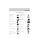
Introduction These are some of the symbols you may see on your vehicle.
Introduction Vehicle Symbol Glossary Child Safety Door Lock/Unlock Interior Luggage Compartment Release Symbol Panic Alarm Engine Oil Engine Coolant Engine Coolant Temperature Do Not Open When Hot Battery Avoid Smoking, Flames, or Sparks Battery Acid Explosive Gas Fan Warning Power Steering Fluid Maintain Correct Fluid Level Emission System Engine Air Filter Passenger Compartment Air Filter Jack MAX MIN 5
Instrumentation Headlamp control (pg. 16) Instrument cluster (pg. 8) Panel dimmer (pg. 17) F H 60 C 2 100 1 20 180 MPH LOW COOLANT km/h THEFT P 120 R N D 2 1 A OFF ON Trunk release — sedan only (pg. 56) Rear window wiper and washer — wagon only* (pg. 47) * if equipped 6 Parking brake release (pg. 114) Turn signal and wiper/washer control (pg. 46) + 140 0 00000 20 E – 60 0 0 0 0 80 40 FUEL DOOR > Driver air bag (pg.
Instrumentation Electronic sound system (pg. 28) 3 4 5 RPMx1000 6 7 ABS ! P BRAKE CRUISE VOL PUSH ON AM H FM M BAL SEEK SET+ TUNE DISC 1-6 CST- BASS TREB EJ TAPE REW FF SIDE 1-2 1 2 3 4 COMP SHUFFLE 5 6 FADE SCAN OFF R RES CD A/C MAX A/C Speed control (pg. 43) Climate control system (pg. 18) Gearshift (pg. 117) Auxiliary power point (pg.
Instrumentation WARNING LIGHTS AND CHIMES F FUEL DOOR > H 60 E C 3 4 5 2 RPMx1000 100 6 1 20 180 MPH LOW COOLANT + 140 0 00000 20 – 60 0 0 0 0 80 40 km/h THEFT P R N D D 1 120 0 7 ABS ! P BRAKE CRUISE Turn signal Illuminates when the left or right turn signal or the hazard lights are turned on. If one or both of the indicators stay on continuously or flash faster, check for a burned-out turn signal bulb. Refer to Exterior bulbs in the Maintenance and care chapter.
Instrumentation Safety belt Momentarily illuminates when the ignition is turned to the ON position to remind you to fasten your safety belts. For more information, refer to the Seating and safety restraints chapter. Door ajar Illuminates when the ignition is in the ON or START position and any door is open. Service engine soon Your vehicle is equipped with a computer that monitors the engine’s emission control system. This system is commonly known as the On Board Diagnostics System (OBD II).
Instrumentation 3. The fuel cap may not have been properly installed and securely tightened. These temporary malfunctions can be corrected by filling the fuel tank with high quality fuel of the recommended octane and/or properly installing and securely tightening the gas cap. After three driving cycles without these or any other temporary malfunctions present, the light should turn off. (A driving cycle consists of a cold engine startup followed by mixed city/highway driving.
Instrumentation stays on, you should check the coolant level inside the reservoir. For instructions on adding coolant, see Engine coolant in the Maintenance and care chapter. Anti-theft system (if equipped) Refer to Perimeter alarm system (if equipped) and SecuriLocky passive anti-theft system in the Controls and features chapter. THEFT Anti-lock brake system (ABS) (If equipped) Momentarily illuminates when the ignition is turned to the ON ABS position.
Instrumentation Brake system warning Momentarily illuminates when the ! P ignition is turned to the RUN position. Also illuminates if the BRAKE parking brake is engaged. If the brake warning lamp does not illuminate at these times, or remains on after releasing the parking brake, seek service immediately. One of the following conditions may exist: • low brake fluid level in the reservoir. • Brake force distribution system failure. The ABS light will also illuminate if this condition is present.
Instrumentation Safety belt warning chime Sounds to remind you to fasten your safety belts. For information on the safety belt warning chime, refer to the Seating and safety restraints chapter. Supplemental restraint system (SRS) warning chime For information on the SRS warning chime, refer to the Seating and safety restraints chapter. Key-in-ignition warning chime Sounds when the key is left in the ignition in the OFF/LOCK or ACC position and the driver’s door is opened.
Instrumentation Tachometer Indicates the engine speed in revolutions per minute. Driving with your tachometer pointer continuously at the top of the scale may damage the engine. 3 4 5 2 RPMx1000 6 1 0 Engine coolant temperature gauge Indicates the temperature of the engine coolant. At normal operating temperature, the needle remains within the normal area (the area between the “H” and “C”). If it enters the red section, the engine is overheating.
Instrumentation Odometer Registers the total kilometers (miles) of the vehicle. 60 0 0 0 0 80 40 100 60 140 100 0 00000 20 20 180 MPH P Trip odometer Registers the kilometers (miles) of individual journeys. To reset, depress the control. km/h 120 R N D D 1 60 0 0 0 0 80 40 60 140 100 0 00000 20 20 180 MPH P km/h 120 R N D D1 Fuel gauge Displays approximately how much fuel is in the fuel tank (when the key is in the ON position).
Controls and features HEADLAMP CONTROL Rotate the headlamp control to the first position to turn on the parking lamps. Rotate to the second position to also turn on the headlamps. A Daytime running lamps (DRL) (if equipped) Turns the headlamps on with a reduced output. To activate: • the ignition must be in the ON position and • the headlamp control is in the OFF or Parking lamps position. Always remember to turn on your headlamps at dusk or during inclement weather.
Controls and features Foglamp control (if equipped) The headlamp control also operates the foglamps. The foglamps can be turned on only when the headlamp control is in the position and the high beams are not turned on. Pull headlamp control towards you to turn foglamps on. The foglamp indicator light will illuminate. A PANEL DIMMER CONTROL Use to adjust the brightness of the instrument panel during headlamp and parklamp operation. • Rotate up to brighten. • Rotate down to dim.
Controls and features REAR WINDOW DEFROSTER The rear defroster control is located on the instrument panel. Press the rear defroster control to clear the rear window of thin ice R and fog. • A small LED will illuminate when the rear defroster is activated. The ignition must be in the ON position to operate the rear window defroster. The defroster turns off automatically after 10 minutes or when the ignition is turned to the OFF position.
Controls and features Temperature control knob Controls the temperature of the airflow inside the vehicle. Mode selector control Controls the direction of the airflow to the inside of the vehicle. A/C The air conditioning compressor will operate in all modes except(Panel) and (Floor). However, the air conditioning will only function if the outside temperature is about 10°C (50°F) or higher.
Controls and features • (Panel and floor)-Distributes outside air through the instrument panel registers and the floor ducts. Heating and air conditioning capabilities are provided in this mode. For added customer comfort, when the temperature control knob is anywhere in between the full hot and full cold positions, the air distributed through the floor ducts will be slightly warmer than the air sent to the instrument panel registers.
Controls and features • Remove any snow, ice or leaves from the air intake area (at the bottom of the windshield under the hood). • If the air conditioner works well in MAX A/C, but not in A/C, this may indicate that the cabin air filter (if equipped) needs to be replaced. • If your vehicle has been parked with the windows closed during hot weather, the air conditioner will do a much faster job of cooling if you drive for two or three minutes with the windows open.
Controls and features Electronic Automatic Temperature Control (EATC) system (if equipped) OUTSIDE TEMP OFF MAX F R A/C AUTO TEMP The EATC system will maintain a selected temperature and automatically control airflow. You can override automatic operation with any of the override controls or the fan speed control. Turning the EATC on OUTSIDE TEMP OFF MAX F R A/C AUTO TEMP Press AUTO, any of the override controls or the fan speed control. The EATC will only operate when the vehicle is running.
Controls and features Turning the EATC off Press OFF. The Outside Temperature function will continue to operate until the ignition is turned off. OUTSIDE TEMP OFF MAX A/C AUTO TEMP Automatic operation Press AUTO and select the desired temperature. The selected temperature and the word AUTO will appear in the display window. The EATC system will either heat or cool to achieve the selected temperature.
Controls and features To control the temperature, select any temperature between 18°C (65°F) and 29°C (85°F) by pressing the temperature control. OUTSIDE TEMP OFF MAX A/C AUTO TEMP For continuous maximum cooling, push the temperature control until 16°C (60°F) is shown in the display window. The EATC will continue maximum cooling (disregarding the displayed temperature) until a warmer temperature is selected by pressing the temperature control.
Controls and features The display will show and a bar graph to indicate manual fan operation and relative speed. AUTO F FAN • • • To return to automatic fan operation, press AUTO. Manual override controls OUTSIDE TEMP OFF MAX F R A/C AUTO TEMP The override controls are located at the bottom of the EATC and allow you to determine where airflow is directed. To return to full automatic control, press AUTO. The air conditioning compressor can operate in all modes except and .
Controls and features • F -Distributes outside air through the windshield defroster ducts. It can be used to clear ice or fog from the windshield. If the outside air temperature is about 10°C (50°F) or higher, the air conditioner will automatically dehumidify the air to reduce fogging. • R (Rear Window Defroster) — Refer to Rear Window Defroster. -Distributes outside air through the windshield defroster ducts • and the floor ducts. Heating and air conditioning capabilities are provided in this mode.
Controls and features Displaying outside temperature Press OUTSIDE TEMP to display TEMP OFF the outside air temperature. It will be displayed until OUTSIDE TEMP MAX A/C is pressed again or until any other control is pressed. When the EATC system is off and OUTSIDE TEMP is AUTO TEMP pressed, the outside temperature will only be displayed for four seconds. The outside temperature reading is most accurate when the vehicle is moving. Higher readings may be obtained when the vehicle is not moving.
Controls and features • If the air conditioner works well in MAX A/C but not in normal A/C, this may indicate that the cabin air filter (if equipped) needs to be replaced. • Do not place objects over the defroster outlets. These objects can block airflow and reduce your ability to see through your windshield. Also, avoid placing small objects on top of your instrument panel. These objects can fall down into the defroster outlets and block airflow and possibly damage your climate control system.
Controls and features Volume/power control Press the control to turn the audio system on or off. Turn control to raise or lower volume. If the volume is set above a certain level and the ignition is turned off, the volume will come back on at a “nominal” listening level when the ignition switch is turned back on. If you wish to maintain your preset volume level, turn the audio system off with the power control before switching off the ignition. AM/FM select The AM/FM select control works in radio mode.
Controls and features Tune adjust in radio mode • Press the to move to the next frequency down the band (whether or not a listenable station is located there). Hold the control to move through the frequencies quickly. • Press the right side of the control to move to the next frequency up the band (whether or not a listenable station is located there). Hold the control to move through the frequencies quickly. Seek function The seek function control works in radio mode.
Controls and features 3. Press and hold a memory preset control until the sound returns, indicating the station is held in memory on the control you selected. Bass/treble adjust • The bass adjust control allows you to increase or decrease the audio system’s bass output. • The treble adjust control allows you to increase or decrease the audio system’s treble output. Speaker balance/fade adjust • Speaker sound distribution can be adjusted between the right and left speakers.
Controls and features MACHT Audio System with AM/FM Stereo/Cassette Volume/power control Press the control to turn the audio system on or off. Turn control to raise or lower volume. If the volume is set above a certain level and the ignition is turned off, the volume will come back on at a “nominal” listening level when the ignition switch is turned back on. If you wish to maintain your preset volume level, turn the audio system off with the power control before switching off the ignition.
Controls and features AM/FM select The AM/FM select control works in radio, tape and CD modes (if equipped). Press the AM or FM control to enter into radio mode. AM/FM select in radio mode This control allows you to select AM or FM frequency bands. Press the control to switch between AM, FM1 or FM2 memory preset stations. Pressing the AM or FM controls when the ignition is turned on will also engage the radio. AM/FM select in tape mode Press this control to stop tape play and begin radio play.
Controls and features • Press to select the next disc in the CD changer. Hold the control to fast-forward through the remaining discs. Seek function The seek function control works in radio, tape or CD mode. Seek function in radio mode • Press to find the next listenable station down the frequency band. to find the next listenable station up the frequency band. • Press Seek function in tape mode • Press to listen to the previous selection on the tape. to listen to the next selection on the tape.
Controls and features Scan function in CD mode Press the SCAN control to hear a short sampling of all selections on the CD. (The CD scans in a forward direction, wrapping back to the first track at the end of the CD.) To stop on a particular selection, press the control again. Radio station memory preset The radio is equipped with six station memory preset controls. These controls can be used to select up to six preset AM stations and twelve FM stations (six in FM1 and six in FM2).
Controls and features • Speaker sound can be adjusted between the front and rear speakers. Inserting a tape Push only slightly when inserting a cassette tape (with the open edge to the right). A cassette deck loading mechanism pulls the tape in the rest of the way. You can switch from CD to tape play by inserting a tape into the cassette deck. Tape/CD select • Pressing the TAPE or CD control when the ignition is on will engage the system if a tape or CD is present in the audio system.
Controls and features • In CD mode, pressing the control for less than three seconds results in slow forward action. Pressing the control for more than three seconds results in fast forward action. • You can cancel the fast forward mode by pressing TAPE, or the FF control. Tape direction select Press SIDE 1–2 to play the alternate side of a tape. DolbyT noise reduction Dolbyt noise reduction operates only in tape mode. Dolbyt noise reduction reduces the amount of hiss and static during tape playback.
Controls and features Setting the clock To set the hour, press and hold the hour (H) control. When the desired hour appears, release the control. To set the minute, press and hold the minute (M) control. When the desired minute appears, release the control. Your vehicle is equipped with a special feature that allows you to access clock mode when the vehicle is not running. Press the H or M control to engage the clock at this time.
Controls and features 3. Turn the magazine (A) over. 4. Using the disc holder release knob (C), pull the disc holder (B) out of the magazine. A B C A If you pull too hard on the disc holder, the disc holder may come completely out of the magazine. If this happens, reinsert the disc holder back into the magazine while pressing on the lever (A). 5. Line up the CD with the groove of the disc holder. Ensure that the label on the CD faces downwards. 6.
Controls and features Ensure that the disc holder is evenly inserted and at the same level as the magazine (A). The unit will not operate if the disc holder is not inserted at the same level (B). A B Radio power must be turned on to play the CDs in the changer. The magazine may be stored in the glove box when not being used. The CD magazine may be inserted or ejected with the radio power off. ONLY use the magazine supplied with the CD changer, other types will damage the unit.
Controls and features Cleaning compact discs Inspect all discs for contamination before playing. If necessary, clean discs only with an approved CD cleaner and wipe from the center out to the edge. Do not use circular motion. CD and CD changer care • Handle discs by their edges only. Never touch the playing surface. • Do not expose discs to direct sunlight or heat sources for extended periods of time. • Do not insert more than one disc into each slot of the CD changer magazine.
Controls and features Radio reception factors Three factors can affect radio reception: • Distance/strength. The further an FM signal travels, the weaker it is. The listenable range of the average FM station is approximately 40 km (24 miles). This range can be affected by “signal modulation.” Signal modulation is a process radio stations use to increase their strength/volume relative to other stations. • Terrain.
Controls and features TRACTION CONTROLY (IF EQUIPPED) This control can be used to turn the Traction Controly on or off. Refer to the Traction Controly section of the Driving chapter for more information. O F T/C F POSITIONS OF THE IGNITION 1. ACCESSORY, allows the electrical 3 accessories such as the radio to 2 operate while the engine is not running. 2. LOCK, locks the steering wheel, automatic transmission gearshift 4 1 lever and allows key removal. 5 3.
Controls and features Do not shift the gearshift lever into N (Neutral) with the speed control on. To turn speed control off • Press OFF or • Turn off the vehicle ignition. OFF ON Once speed control is switched off, the previously programmed set speed will be erased. To set a speed • Press SET+. For speed control to operate, the speed control must be ON and the vehicle speed must be greater than 48 km/h (30 mph).
Controls and features To set a higher set speed • Press and hold SET +. Release the control when the desired SET+ vehicle speed is reached or RES CST • Press and release SET +. Each press will increase the set speed by 1.6 km/h (1 mph) or • Accelerate with your accelerator pedal. When the desired vehicle speed is reached, press and release SET +. You can accelerate with the accelerator pedal at any time during speed control usage.
Controls and features Pressing OFF will erase the previously programmed set speed. OFF ON To return to a previously set speed • Press RES/RSM/RESUME. For RES/RSM/RESUME to operate, the vehicle speed must be faster than 48 km/h (30 mph). SET+ RES CST Indicator light This light comes on when either the CRUISE SET ACC/SET ACCEL or RES/RSM/ RESUME controls are pressed. It turns off when the speed control OFF control is pressed, the brake is applied or the ignition is turned to the OFF position.
Controls and features Push the control on the end of the stalk to activate washer. Push and hold for a longer wash cycle. The washer will automatically shut off after ten seconds of continuous use. Mist Function To operate the Mist function of the windshield wipers, push and release the windshield washer control quickly. The wipers will cycle one or two times.
Controls and features TILT STEERING Pull the tilt steering control toward you to move the steering wheel up or down. Hold the control while adjusting the wheel to the desired position, then release the control. Never adjust the steering wheel when the vehicle is moving. DOME LAMPS AND MAP LAMPS The front dome lamp is located overhead between the driver and passenger seats. If the vehicle is equipped with a moon roof, the dome lamp is located behind the moon roof.
Controls and features The map lamp controls (if equipped) are located on the dome lamp. Press the controls on either side of each lens on each map lamp to activate the lamps. If equipped with a moon roof, the map lamps are located on the moon roof control panel. Press the controls on either side of each map lamp to activate the lamps. REAR DOME LAMP (IF EQUIPPED) The dome lamp lights when: • any door is opened with the control in the middle position.
Controls and features ILLUMINATED VISOR MIRROR (IF EQUIPPED) To turn on the visor mirror lamps, lift the mirror cover. Adjust the amount of light by sliding the control. MOON ROOF (IF EQUIPPED) To open, press and hold the rear portion of the control. This will fully open the moon roof. To close, press and hold the front portion of the control.
Controls and features You will need a Phone Adapter System (PAS) that is compatible with your cell phone that you install into the center console. This system includes a Phone Adapter Module (PAM) with a Wiring Harness and a Hang-Up Cup. For more information, call 1–800–736–9450 to order the Phone Adapter System (PAS) for your specific phone. To install the PAS, locate the four screw holes in the console. Install the PAM and the hang-up cup with four screws.
Controls and features POWER WINDOWS Press and hold the rocker switches to open and close windows. • Press the top portion of the rocker switch to close. AUTO • Press the bottom portion of the rocker switch to open. AUTO One touch down • Press AUTO completely down to the second detent. The driver’s window will open fully. Depress up to stop window operation.
Controls and features Window lock The window lock feature allows only the driver to operate the power windows. To lock out all the window controls except for the driver’s press the left side of the control. Press the right side to restore the window controls. Accessory delay (if equipped) With accessory delay, the window switches may be used for up to ten minutes after the ignition switch is turned to the OFF position or until any door is opened.
Controls and features POWER SIDE VIEW MIRRORS To adjust your mirrors: to adjust the left 1. Select mirror or to adjust the right mirror. 2. Move the control in the direction you wish to tilt the mirror. 3. Return to the center position to disable adjust function. Heated outside mirrors (if equipped) Both mirrors are heated automatically to remove ice, mist and fog when the rear window defrost is activated.
Controls and features CENTER CONSOLE Your vehicle may be equipped with a variety of console features. These include: • Utility compartment • Bin mat (snap-in) • Cupholders (front and rear) • Coin holder slots • Compact disc changer (if equipped) • Tissue holder • Rear A/C vent • Rear ashtray (see your Ford, Lincoln Mercury dealer to obtain rear ashtray Use only soft cups in the cupholder. Hard objects can injure you in a collision.
Controls and features TRUNK REMOTE CONTROL Press the remote trunk release control on the instrument panel to the left of the steering wheel. LIFTGATE (WAGON ONLY) You can open and close the liftgate and the liftgate window from outside the vehicle. It cannot be opened from inside the cargo area. • To open the liftgate window, unlock the liftgate (with the key, the power door locks or the remote entry key fob) and push the key lock cylinder.
Controls and features CARGO AREA FEATURES Storage compartment Your vehicle comes equipped with a storage compartment in the floor of the cargo area. An additional compartment is in the rear trim panel on the right. Always put the load you are carrying as far forward as possible. Cargo net (if equipped) (Wagon) The cargo net secures lightweight objects in the cargo area. Attach the net to the anchors provided. Do not put more than 22 kg (50 lbs.) in the net.
Controls and features To prevent the possibility of injuries, the fasteners for the cargo area cover must be properly attached to the mounting clips on the rear trim panels. Do not place any objects on the cargo area cover. They may obstruct your vision or strike occupants of the vehicle in the case of a sudden stop or collision. Rewinding the shade With extended use, the cargo shade may lose its spring tension. If this occurs, the shade must be manually rewound. This is a two-person operation. 1.
Controls and features 7. Insert the shade into the side mounting brackets and check to make sure that it operates properly. The cover may cause injury in a sudden stop or accident if it is not securely installed. Cargo utility hooks (Sedan) The utility hooks located in side the trunk can be used to hang small items on. Do not hang more than 12 kg (20 lbs) on the hooks. The hooks are not designed to restrain objects during a collision.
Controls and features Locking the doors/liftgate Press this control to lock all doors and liftgate (wagons). To confirm all doors are closed and locked, press the control a second time within three seconds. The doors will lock again and the horn will chirp. If any of the doors or liftgate are ajar, the horn will make two quick chirps, reminding you to properly close all doors. Unlocking the liftgate/trunk Press the control to unlock the liftgate/trunk.
Controls and features Changes or modifications not expressly approved by the party responsible for compliance could void the user’s authority to operate the equipment. Illuminated entry The interior lamps illuminate when the remote entry system is used to unlock the door(s). The system automatically turns off after 25 seconds or when the ignition is turned to the ON or ACC position. The dome lamp control (if equipped) must not be set to the OFF position for the illuminated entry system to operate.
Controls and features To program the transmitters yourself: • Insert a key in the ignition and 3 turn from 3 (OFF) to 4 (ON) 2 eight times in rapid succession (within 10 seconds) with the 4 eighth turn ending in the 4 (ON) position. The doors will 1 5 lock/unlock to confirm that programming mode has been entered. • Within 20 seconds, program a remote transmitter by pressing any button on a transmitter. The doors will lock/unlock to confirm that the remote transmitter has been programmed.
Controls and features To replace the battery: 1. Twist a thin coin between the two halves of the transmitter near the key ring. DO NOT TAKE THE FRONT PART OF THE TRANSMITTER APART. 2. Place the positive (+) side of new battery in the same orientation. Refer to the diagram inside the transmitter unit. 3. Snap the two halves back together. Replacement of the battery will not cause the remote transmitter to become deprogrammed from your vehicle.
Controls and features • Press 7/8 and 9/0 controls on the keyless entry pad at the same time to lock the doors (doors opened or closed). 1 2 3 4 5 6 7 8 9 0 • Open a door and press the power door lock control to lock the doors. There is a 20 second countdown when any of the above actions occur before the vehicle becomes ARMED. Each door/hood or liftgate (wagon) arm individually, and if any door/hood or liftgate (wagon) is open, then it must be closed for it to be armed.
Controls and features Disarming the system You can disarm the system by any of the following actions: • Unlock the doors by using your remote entry transmitter. • Unlock the doors by using your keyless entry pad. 1 2 3 4 5 6 7 8 9 0 • Unlock the doors or liftgate with a key. Turn the key full travel (toward the front of the vehicle) to make sure the alarm disarms. • Turn ignition to ON. • Press the PANIC control on the remote entry transmitter.
Controls and features KEYLESS ENTRY SYSTEM (IF EQUIPPED) With the keyless entry keypad, you can: 1 2 3 4 5 6 7 8 9 0 • lock or unlock the vehicle doors and liftgate (wagons) without using the key • open the trunk • arm and disarm the perimeter alarm system (if equipped) See also Remote entry system and Perimeter alarm system in this chapter for more information. Your vehicle has a factory-set 5–digit code that operates the keyless entry system. You can also program your own 5–digit personal entry code.
Controls and features To exit, press 7/8 and 9/0 simultaneously or allow more than 5 seconds to elapse since a button press occured and the 5 digit keycode will be programed. If you wish to erase your personal code, use the following instructions: Erasing personal code 1. Enter the factory-set code. 2. Press 1/2 within five seconds of step 1 and release. 3. Press the 1/2 control and hold for 2 seconds to erase the customer programmed keycode, within five seconds of step 2.
Controls and features 3. To unlock the trunk or liftgate (wagon), enter the five-digit factory-set code, then press the 5/6 control within five seconds. Locking the doors and liftgate (wagon), press the 7/8 and 9/0 controls at the same time. This can be done at any time.
Controls and features Deactivating/activating horn chirp There are 2 methods to enable/disable this feature. One through your dealer and the second with a door lock sequence using the following instructions: 1. Turn the ignition key to RUN, then press the door UNLOCK control button 3 times. 2. Turn the ignition key to OFF, then press the door UNLOCK control button 3 times. 3. Turn the ignition key to RUN, within five seconds press the door UNLOCK control button 2 times.
Controls and features momentary problem if they are too close to the key during engine start. If a problem occurs, turn the ignition OFF and restart the engine with all other objects on the key ring held away from the ignition key. Check to make sure the encoded ignition key is an approved Ford encoded ignition key. Spare SecuriLocky keys can be purchased from your dealership and programmed to your SecuriLocky passive anti-theft system. Refer to Programming spare SecuriLocky keys for more information.
Controls and features 2. Turn ignition to OFF and remove the first SecuriLocky key from the ignition. 3. Within five seconds of turning the ignition to OFF, insert the second previously programmed SecuriLocky key into the ignition and turn the ignition from OFF to ON (maintain ignition in ON for at least one second but no more than five seconds). 4. Turn the ignition to OFF and remove the second SecuriLocky key from the ignition. 5.
Controls and features To open the luggage compartment door (lid) from the inside, pull the illuminated “T” shaped handle and push up on the trunk lid. The material that the handle is made of will glow for hours in the darkness of the luggage compartment following brief exposure to ambient light. The “T” shaped handle will be located either on the luggage compartment door (lid) or inside the luggage compartment near the tail lamps.
Seating and safety restraints SEATING Adjustable head restraints Your vehicle’s seats are equipped with head restraints which are vertically adjustable. The purpose of these head restraints is to help limit head motion in the event of a rear collision. To properly adjust your head restraints, lift the head restraint so that it is located directly behind your head or as close to that position as possible. Refer to the following to raise and lower the head restraints.
Seating and safety restraints Always drive and ride with your seatback upright and the lap belt snug and low across the hips. Reclining the seatback can reduce the effectiveness of the seat’s safety belt in the event of a collision. Lift handle to move seat forward or backward. Pull lever up to adjust seatback. Adjusting the front power seat (if equipped) Never adjust the driver’s seat or seatback when the vehicle is moving.
Seating and safety restraints Reclining the seatback can reduce the effectiveness of the seat’s safety belt in the event of a collision. The control is located on the outboard side of the seat cushion. Press front to raise or lower the front portion of the seat cushion. Press rear to raise or lower the rear portion of the seat cushion. Press the control to move the seat forward, backward, up or down.
Seating and safety restraints REAR SEATS 2nd seat/Split-folding rear seat (if equipped) One or both rear seatbacks can be folded down to provide additional cargo space. To lower the seatback(s) from inside the vehicle, pull tab to release seat back and then fold seatback down. When raising the seatback(s), make sure you hear the seat latch into place. 3rd seat (wagon only) The third seat faces the rear of the vehicle. For height and weight limits, see the label on the seat cushion.
Seating and safety restraints To open up the seat: 1. Unlock the floor panel with the key, then use the handle to fold the floor panel toward the front of the car. 2. Remove the cargo cover. The cargo cover must be removed or the seatback will not latch in the upright position. 3. Lift the remote latch release on the left side of the compartment and fold the remaining floor panel until it latches. Make sure the seatback is locked in the upright position.
Seating and safety restraints SAFETY RESTRAINTS Personal Safety System The Personal Safety System provides an improved overall level of frontal crash protection to front seat occupants and is designed to help further reduce the risk of air bag-related injuries. The system is able to analyze different occupant conditions and crash severity before activating the appropriate safety devices to help better protect a range of occupants in a variety of frontal crash situations.
Seating and safety restraints common, moderate-severity impacts. A higher energy level is provided for the most severe impacts. Whether or not the air bag deploys at all can also be different for the driver versus the passenger based upon driver’s seat position and safety belt usage allowing further tailoring of the system.
Seating and safety restraints When are the front air bags and pretensioners deployed? Front air bags and pretensioners are designed to activate in frontal and near-frontal collisions, not rollover, side-impacts, or rear-impacts unless the collision causes sufficient longitudinal deceleration. The fact that the pretensioners or air bags did not activate in a collision does not mean that something is wrong with the system.
Seating and safety restraints In a rollover crash, an unbelted person is significantly more likely to die than a person wearing a seat belt. Each seating position in your vehicle has a specific safety belt assembly which is made up of one buckle and one tongue that are designed to be used as a pair. 1) Use the shoulder belt on the outside shoulder only. Never wear the shoulder belt under the arm. 2) Never swing the safety belt around your neck over the inside shoulder.
Seating and safety restraints Energy management retractors Your vehicle has a seat belt system equipped with energy management retractors at the driver and front outboard passenger seating positions. An energy management retractor is a device which pays out webbing in a controlled manner. This feature is designed to help further reduce the risk of force-related injuries to the occupant.
Seating and safety restraints Automatic locking mode In this mode, the shoulder belt is automatically pre-locked. The belt will still retract to remove any slack in the shoulder belt. The automatic locking mode is not available on the driver safety belt. When to use the automatic locking mode • Anytime a child safety seat is installed in the vehicle. Children 12 years old and under should be properly restrained in the rear seat whenever possible.
Seating and safety restraints • Allow the belt to retract. As the belt retracts, you will hear a clicking sound. This indicates the safety belt is now in the automatic locking mode. How to disengage the automatic locking mode Disconnect the combination lap/shoulder belt and allow it to retract completely to disengage the automatic locking mode and activate the vehicle sensitive (emergency) locking mode.
Seating and safety restraints Safety belt usage sensors The driver and front outboard passenger safety belt buckles are equipped with sensors that detect if the safety belts are fastened. The sensors provide information to the Personal Safety System which can then adapt the air bag deployment or safety belt pretensioner activation based upon safety belt usage. The Personal Safety System provides the most benefit to belted occupants.
Seating and safety restraints Lap belts Adjusting the lap belt The lap belt does not adjust automatically. The lap belts should fit snugly and as low as possible around the hips, not around the waist. Insert the tongue into the correct buckle (the buckle closest to the direction the tongue is coming from). To lengthen the belt, turn the tongue at a right angle to the belt and pull across your lap until it reaches the buckle.
Seating and safety restraints When the adjust tongue of the lap/shoulder combination seat belt is latched into the buckle, the tongue will allow the lap portion to become shorter, but locks the webbing in place to restrict it from becoming longer. Before you reach and latch a combination lap and shoulder belt having an adjust tongue into the buckle, you may have to lengthen the lap belt portion of it. To lengthen the lap belt, pull some webbing out of the shoulder belt retractor.
Seating and safety restraints To unfasten the belt, push the red release button on the end of the buckle. This allows the tongue to unlatch from the buckle. While the belt retracts, guide the tongue to its original position to prevent it from striking you or the vehicle. Safety belt extension assembly If the safety belt assembly is too short, even when fully extended, 20 cm (8 inches) can be added to the safety belt assembly by adding a safety belt extension assembly (part number 611C22).
Seating and safety restraints Belt minder (if equipped) The Belt Minder feature is a supplemental warning to the safety belt warning function. This feature provides additional reminders to the driver that the driver’s safety belt is unbuckled by intermittently sounding a chime and illuminating the safety belt warning lamp in the instrument cluster. If...
Seating and safety restraints The following are reasons most often given for not wearing safety belts: (All statistics based on U.S. data) Reasons given... 9Crashes are rare events9 Consider... 36 700 crashes occur every day. The more we drive, the more we are exposed to 9rare9 events, even for good drivers. 1 in 4 of us will be seriously injured in a crash during our lifetime. 9I’m not going far9 3 of 4 fatal crashes occur within 25 miles of home.
Seating and safety restraints One time disable Anytime the safety belt is buckled and then unbuckled during an ignition ON cycle, Belt Minder will be disabled for that ignition cycle only. The safety belt needs to be latched for a minimum of 3 seconds before belt minder is disabled. Deactivating/activating the belt minder feature Read steps 1 - 9 thoroughly before proceeding with the deactivation/activation programming procedure.
Seating and safety restraints • After step 5 the safety belt warning light will be turned on for three seconds. 6. Within seven seconds of the safety belt warning light turning off, buckle then unbuckle the safety belt. • This will disable Belt Minder if it is currently enabled, or enable Belt Minder if it is currently disabled. 7. Confirmation of disabling Belt Minder is provided by flashing the safety belt warning light four times per second for three seconds. 8.
Seating and safety restraints AIR BAG SUPPLEMENTAL RESTRAINT SYSTEM – + 100 0 0 0 0 F FUEL DOOR > 3 140 60 H C LOW COOLANT 4 5 2 RPMx1000 0 00000 E 6 1 20 180 km/h THEFT P R N D 2 1 0 7 ABS ! P BRAKE CRUISE H AM FM VOL PUSH ON A CST- BASS TREB M BAL SEEK SET+ OFF TUNE DISC 1-6 EJ TAPE REW FF SIDE 1-2 1 2 3 4 CD COMP SHUFFLE 5 6 FADE SCAN ON OFF R RES A/C MAX A/C Your vehicle is equipped with a crash sensing and diagnostic module which records information
Seating and safety restraints The air bag supplemental restraints are an intergral part of the Personal Safety System. They are designed to be deployed in cases where the Personal Safety System has determined the occupant conditions and crash severity are appropriate to activate these devices. Refer to the Personal Safety System section in this chapter.
Seating and safety restraints • Recline the seat slightly (one or two degrees) from the upright position. Do not put anything on or over the air bag module. Placing objects on or over the air bag inflation area may cause those objects to be propelled by the air bag into your face and torso causing serious injury. Do not attempt to service, repair, or modify the Air Bag Supplemental Restraint System or its fuses. See your Ford or Lincoln-Mercury dealer.
Seating and safety restraints Determining if the system is operational The supplemental restraint system uses a warning indicator in the instrument cluster or a back-up tone to indicate the condition of the system. Refer to the Restraints Warning Indicator section in the Instrumentation chapter. Routine maintenance of the air bag is not required.
Seating and safety restraints facial and eye injuries or internal injuries, particularly to occupants who are not properly restrained or are otherwise out of position at the time of air bag deployment. Thus, it is extremely important that occupants be properly restrained as far away from the air bag module as possible while maintaining vehicle control. Several air bag system components get hot after inflation. Do not touch them after inflation.
Seating and safety restraints How does the side air bag system work? The side air bag system consists of the following: • An inflatable nylon bag (air bag) with a gas generator concealed behind the outboard bolster of the driver and front passenger seatbacks. • A special seat cover designed to allow airbag deployment. • The same warning light, electronic control and diagnostic unit as used for the front air bags. • Two crash sensors located under the outboard side of the front seats, attached to the floor.
Seating and safety restraints Several air bag system components get hot after inflation. Do not touch them after inflation. If the side air bag has deployed, the air bag will not function again. The side air bag system (including the seat) must be inspected and serviced by a qualified technician in accordance with the vehicle service manual. If the air bag is not replaced, the unrepaired area will increase the risk of injury in a collision.
Seating and safety restraints Never let a passenger hold a child on his or her lap while the vehicle is moving. The passenger cannot protect the child from injury in a collision. Always follow the instructions and warnings that come with any infant or child restraint you might use. When possible, always place children under age 12 in the rear seat of your vehicle. Accident statistics suggest that children are safer when properly restrained in the rear seating positions than in the front seating position.
Seating and safety restraints SAFETY SEATS FOR CHILDREN Child and infant or child safety seats Use a safety seat that is recommended for the size and weight of the child. Carefully follow all of the manufacturer’s instructions with the safety seat you put in your vehicle. If you do not install and use the safety seat properly, the child may be injured in a sudden stop or collision.
Seating and safety restraints of providing a tether anchorage. For more information on top tether straps, refer to Attaching safety seats with tether straps. Carefully follow all of the manufacturer’s instructions included with the safety seat you put in your vehicle. If you do not install and use the safety seat properly, the child may be injured in a sudden stop or collision.
Seating and safety restraints 2. Pull down on the shoulder belt and then grasp the shoulder belt and lap belt together. 3. While holding the shoulder and lap belt portions together, route the tongue through the child seat according to the child seat manufacturer’s instructions. Be sure the belt webbing is not twisted. 4. Insert the belt tongue into the proper buckle (the buckle closest to the direction the tongue is coming from) for that seating position until you hear a snap and feel the latch engage.
Seating and safety restraints 5. To put the retractor in the automatic locking mode, grasp the shoulder portion of the belt and pull downward until all of the belt is extracted and a click is heard. 6. Allow the belt to retract. The belt will click as it retracts to indicate it is in the automatic locking mode. 7. Pull the lap belt portion across the child seat toward the buckle and pull up on the shoulder belt while pushing down with your knee on the child seat. 8.
Seating and safety restraints Installing child safety seats in the lap belt seating positions 1. Lengthen the lap belt. To lengthen the belt, hold the tongue so that its bottom is perpendicular to the direction of webbing while sliding the tongue up the webbing. 2. Place the child safety seat in the center seating position. 3. Route the tongue and webbing through the child seat according to the child seat manufacturer’s instructions. 4.
Seating and safety restraints 1. Position the child safety seat on the passenger seat cushion. 2. Route the child safety seat tether strap over the back of the seat. For vehicles with adjustable head restraints, route the tether strap under the head restraint and between the head restraint posts, otherwise route the tether strap over the top of the seatback. 3. Locate the correct anchor for the selected seating position. 4. Open the tether anchor cover. 5. Clip the tether strap to the anchor as shown.
Starting PREPARING TO START YOUR VEHICLE Engine starting is controlled by the powertrain control system. This system meets all Canadian Interference-Causing Equipment standard requirements regulating the impulse electrical field strength of radio noise. When starting a fuel-injected engine, avoid pressing the accelerator before or during starting. Only use the accelerator when you have difficulty starting the engine. For more information on starting the vehicle, refer to Starting the engine in this chapter.
Starting 2. Make sure the headlamps and vehicle accessories are off. 3. Make sure the parking brake is set. 4. Make sure the gearshift is in P (Park). P R N D D 5. Turn the key to 4 (ON) without 3 turning the key to 5 (START). 2 If there is difficulty in turning the key, firmly rotate the steering wheel 4 left and right until the key turns 1 freely.
Starting F FUEL DOOR > H 60 E C 3 4 5 2 RPMx1000 100 6 1 20 180 MPH LOW COOLANT + 140 0 00000 20 – 60 0 0 0 0 80 40 km/h THEFT P R N D D 1 120 0 7 ABS ! P BRAKE CRUISE Make sure the corresponding lights illuminate briefly. If a light fails to illuminate, have the vehicle serviced. • If the driver’s safety belt is fastened, the light may not illuminate. STARTING THE ENGINE 1.
Starting Using the engine block heater (if equipped) An engine block heater warms the engine coolant, which improves starting, warms up the engine faster and allows the heater-defroster system to respond quickly. Use of an engine block heater is strongly recommended if you live in a region where temperatures reach -23°C (-10°F) or below. For best results, plug the heater in at least three hours before starting the vehicle.
Starting Important ventilating information If the engine is idling while the vehicle is stopped in an open area for long periods of time, open the windows at least 2.5 cm (one inch). Adjust the heating or air conditioning (if equipped) to bring in fresh air. Improve vehicle ventilation by keeping all air inlet vents clear of snow, leaves and other debris.
Driving BRAKES Your service brakes are self-adjusting. Refer to the scheduled maintenance guide for scheduled maintenance. Occasional brake noise is normal and often does not indicate a performance concern with the vehicle’s brake system. In normal operation, automotive brake systems may emit occasional or intermittent squeal or groan noises when the brakes are applied.
Driving ABS warning lamp ABS The ABS warning lamp in the instrument cluster momentarily illuminates when the ignition is turned to the ON position. If the light does not illuminate momentarily at start up, remains on or continues to flash, the ABS needs to be serviced. With the ABS light on, the anti-lock ! P brake system is disabled and normal braking is still effective unless the BRAKE brake warning light also remains illuminated with parking brake released.
Driving Parking brake Apply the parking brake whenever the vehicle is parked. To set the parking brake, press the parking brake pedal down until the pedal stops. The BRAKE warning lamp in the instrument cluster illuminates and remains illuminated (when the ignition is turned ON) until the parking brake is released. ! P BRAKE Always set the parking brake fully and make sure that the gearshift is securely latched in P (Park). The parking brake is not recommended to stop a moving vehicle.
Driving Pull the release lever to release the brake. Driving with the parking brake on will cause the brakes to wear out quickly and reduce fuel economy. TRACTION CONTROLY (IF EQUIPPED) Your vehicle may be equipped with the optional Traction Controly system. This system helps you maintain the stability and steerability of your vehicle. It is especially useful on slippery and/or hilly road surfaces. The system operates by detecting and controlling wheel spin.
Driving During Traction Controly operation, the traction control active light will illuminate, you may hear an electric motor type of sound coming from the engine compartment and the engine will not “rev-up” when you push further on the accelerator. This is normal system behavior. The Traction Controly on/off switch, located on the right side of the instrument cluster, illuminates OFF when the system is turned OFF.
Driving AUTOMATIC TRANSAXLE OPERATION Brake-shift interlock This vehicle is equipped with a brake-shift interlock feature that prevents the gearshift lever from being moved from P (Park) when the ignition is in the ON position unless brake pedal is depressed. If you cannot move the gearshift lever out of P (Park) with ignition in the ON position and the brake pedal depressed: 1. Apply the parking brake, turn ignition key to LOCK, then remove the key. 2. Insert the key and turn it to OFF.
Driving If the parking brake is fully released, but the brake warning lamp remains illuminated, the brakes may not be working properly. See your dealer or a qualified service technician. Driving with an automatic overdrive transaxle Your automatic transaxle electronically controls the shift feel by using an adaptive learning strategy. This feature is designed to optimize shift smoothness.
Driving Understanding gearshift positions P (Park) Always come to a complete stop before shifting into P (Park). Make sure the gearshift lever is securely latched in P (Park). This locks the transaxle and prevent the front wheels from rotating. P R N D D 1 P R N D D 1 Always set the parking brake fully and make sure the gearshift is latched in P (Park). Turn off the ignition whenever you leave your vehicle. R (Reverse) With the gearshift lever in R (Reverse), the vehicle will move backward.
Driving N (Neutral) With the gearshift lever in the N (Neutral) position, the vehicle can be started and is free to roll. Hold the brake pedal down while in this position. P R N D D 1 (Overdrive) The (Overdrive) position is the P R N D D 1 normal driving position for an automatic overdrive transaxle. When in the (Overdrive) position, the transaxle works the same way as when in D (Drive).
Driving When to use D (Drive) The D (Drive) position eliminates the needless shifting back and forth between third and fourth gears that your vehicle may do when driving on hilly terrain. It also gives more engine braking than overdrive to slow your vehicle on downgrades. 1 (First) Use 1 (First) for when added engine braking is desired when descending steep hills. The automatic transaxle will shift to the proper gear to ascend any grade without any need to shift to 1 (First).
Driving When parking, do not use the gearshift in place of the parking brake. Always set the parking brake fully and make sure that the gearshift is securely latched in Park (P). Turn off the ignition whenever you leave your vehicle. Never leave your vehicle unattended while it is running. If you do not take these precautions, your vehicle may move unexpectedly and injure someone.
Driving • Maximum Trailer Weight: Maximum weight of a trailer the loaded vehicle (including passengers and cargo) is permitted to tow. It is determined by subtracting the weight of the loaded trailer towing vehicle from the GCWR for the towing vehicle. • Trailer Weight Range: Specified weight range that the trailer must fall within that ranges from zero to the maximum trailer weight rating. Remember to figure in the tongue load of your loaded trailer when figuring the total weight.
Driving If driving through deep or standing water is unavoidable, proceed very slowly. Never drive through water that is higher than the bottom of the hubs (for trucks) or the bottom of the wheel rims (for cars). Once through the water, always try the brakes. Wet brakes do not stop the vehicle as effectively as dry brakes. Drying can be improved by moving your vehicle slowly while applying light pressure on the brake pedal.
Driving The amount of weight that you can tow depends on the type of engine in your vehicle. See the following charts: Model Sedan Wagon 3.0L 2-Valve Passenger Load #/kg (lbs.) 5/340 (750) 4/270 (600) 2/135 (300) 2/135 (300) 4/270 (600) 2/135 (300) 2/135 (300) Vulcan Engine Luggage Load - Max Trailer kg (lbs.) Wt.- kg (lbs.
Driving Preparing to tow Use the proper equipment for towing a trailer, and make sure it is properly attached to your vehicle. See your dealer or a reliable trailer dealer if you require assistance. Hitches Do not use hitches that clamp onto the vehicle bumper. Use a load carrying hitch. You must distribute the load in your trailer so that 10% of the total weight of the trailer is on the tongue. Safety chains Always connect the trailer’s safety chains to the frame or hook retainers of the vehicle.
Driving Driving while you tow When towing a trailer: • Ensure that you turn off your speed control. The speed control may shut off automatically when you are towing on long, steep grades. • Consult your local motor vehicle speed regulations for towing a trailer. • Use D (Drive) or a lower gear when towing up or down steep hills. This will eliminate excessive downshifting and upshifting for optimum fuel economy and transaxle cooling. • Anticipate stops and brake gradually.
Driving All Front Wheel Drive (FWD) vehicles An example of recreational towing is towing your vehicle behind a Motorhome. The following recreational towing guidelines are designed to ensure that your transmission is not damaged. It is not recommended to tow front wheel drive vehicles with the front drive wheels on the ground. It is recommended to tow your vehicle with the drive wheels on a dolly or two wheel car hauling trailer.
Roadside emergencies GETTING ROADSIDE ASSISTANCE To fully assist you should you have a vehicle concern, Ford offers a complimentary roadside assistance program. This program is separate from the New Vehicle Limited Warranty. The service is available: • 24–hours, seven days a week • for the Basic warranty period (Canada) or New Vehicle Limited Warranty period (U.S.
Roadside emergencies Roadside coverage beyond basic warranty In the United States, you may purchase additional roadside assistance coverage beyond this period through the Ford Auto Club by contacting your Ford or Lincoln Mercury dealer. Similarly in Canada, you may purchase additional coverage beyond the basic coverage period by consulting the Ford Roadside Assistance Club brochure or by calling 1–877–294–CLUB (1–877–894–2582).
Roadside emergencies If your vehicle is a sedan, the fuel pump shut-off switch is located on the right side of the trunk behind the trunk liner. If your vehicle is a wagon, the fuel pump shut-off switch is located behind the service panel on the right side of the cargo area. Use the following procedure to reset the fuel pump shut-off switch. 1. Turn the ignition to the OFF position. 2. Check the fuel system for leaks. 3.
Roadside emergencies FUSES AND RELAYS Fuses If electrical components in the vehicle are not working, a fuse may have blown. Blown fuses are identified by a broken wire within the fuse. Check the appropriate fuses before replacing any electrical components. 15 Always replace a fuse with one that has the specified amperage rating. Using a fuse with a higher amperage rating can cause severe wire damage and could start a fire.
Roadside emergencies 33 37 41 32 36 40 35 39 PULL TAB TO RELEASE 38 42 14 18 22 26 30 13 17 21 25 29 12 16 20 24 28 10 9 11 15 19 23 27 6 5 8 4 3 7 2 1 S E E OW NE RS MA NU AL CONS UL TE R L A G U ID E Passenger compartment fuse panel The fuse panel is located below and to the left of the steering wheel by the brake pedal. Remove the panel cover to access the fuses. To remove a fuse use the fuse puller tool provided on the fuse panel cover. The fuses are coded as follows.
Roadside emergencies Fuse/Relay Location 13 14 15 16 Fuse Amp Rating 20A — 30A 15A 17 15A 18 19 20 21 22 — — — — 20A 23 24 25 26 10A 15A 2A 10A 27 10A 28 29 30 31 32 10A 15A 15A — 10A 33 34 35 36 — — — 15A 134 Passenger Compartment Fuse Panel Description Cigar Lighter, Auxiliary Power Point Not Used Front Wiper Motor Flasher and GEM Power, Integrated Control Panel (ICP) Power, RCC Memory, Cluster Stop Lamp, Speed Control Deactivating Switch Not Used Not Used Not Used Not Used Deck Lid Release
Roadside emergencies Fuse/Relay Location 37 38 39 40 41 42 Fuse Amp Rating 15A 5A — — — — Passenger Compartment Fuse Panel Description Transmission Position Switch GEM Park Neutral Switch Not Used Not Used Not Used Not Used Power distribution box The power distribution box is located in the engine compartment. The power distribution box contains high-current fuses that protect your vehicle’s main electrical systems from overloads. Always disconnect the battery before servicing high current fuses.
32 31 33 30 25 29 24 14 13 28 27 26 23 12 11 15 16 17 18 19 20 21 22 8 10 7 9 6 5 2 4 1 3 Roadside emergencies The high-current fuses are coded as follows.
Roadside emergencies Fuse/Relay Location 21 22 23 24 25 26 27 28 Fuse Amp Rating 15A* 10A* — — — 30A* 5A* 15A* 29 — 30 — 31 — 32 — 33 — * Mini Fuses ** Maxi Fuses Power Distribution Box Description Left Headlamp A/C Clutch Relay, PCM Keep Alive Power Starter Motor Relay Low Speed Fan Relay Wiper Speed Relay Generator Rear Control Unit, Antenna HEGO Sensor Transmission Shift Solenoid, Canister Vent, A/C Clutch Relay, Thermactor Bypass Solenoid Wiper Park Relay Fuel Pump Relay PCM Power Relay High Speed Fa
Roadside emergencies When driving with the temporary spare tire do not: • exceed 80 km/h (50 mph) under any circumstances • load the vehicle beyond maximum vehicle load rating listed on the Safety Compliance Label • tow a trailer • use tire chains • drive through an automatic car wash, because of the vehicle’s reduced ground clearance • try to repair the temporary spare tire or remove it from its wheel • use the wheel for any other type of vehicle Tire change procedure 1.
Roadside emergencies • In the sedan, these are located in the trunk cargo area storage compartment. • In the wagon, they are stored in the left side rear trim panel for the temporary spare and in the floor cargo area storage compartment for the full size spare. 3. If equipped with a wheel cover that’s bolted on, loosen the five plastic nuts with the lug nut wrench. 4. Remove the center ornament or wheel cover from the wheel with the tapered end of the wheel lug nut wrench that came with your vehicle.
Roadside emergencies 5. Loosen each wheel lug nut one-half turn counterclockwise but do not remove them until the wheel is raised off the ground. 6. Put the jack in the jack notch next to the door of the tire you are changing. Turn the jack handle clockwise until the wheel is completely off the ground. 7. Remove the lug nuts with the lug nut wrench. 8. Replace the flat tire with the spare tire, making sure the valve stem is facing outward. Reinstall lug nuts until the wheel is snug against the hub.
Roadside emergencies 11. Return the flat tire, jack and lug wrench to their proper storage locations. Make sure the jack is fastened so it does not rattle when you drive. 12. Unblock the wheels. JUMP STARTING YOUR VEHICLE The gases around the battery can explode if exposed to flames, sparks, or lit cigarettes. An explosion could result in injury or vehicle damage. Do not push start your vehicle. You could damage the catalytic converter.
Roadside emergencies 4. Check all battery terminals and remove any excessive corrosion before you attach the battery cables. Ensure that vent caps are tight and level. 5. Turn the heater fan on in both vehicles to protect any electrical surges. Turn all other accessories off. Connecting the jumper cables + + – – 1. Connect the positive (+) booster cable to the positive (+) terminal of the discharged battery.
Roadside emergencies + + – – 3. Connect the negative (-) cable to the negative (-) terminal of the assisting battery. + + – – 4. Make the final connection of the negative (-) cable. Make the connection to an exposed metal part of the stalled vehicle’s engine, away from the battery and the carburetor/fuel injection system. Do not use fuel lines, engine rocker covers or the intake manifold as grounding points.
Roadside emergencies Jump starting 1. Start the engine of the booster vehicle and run the engine at moderately increased speed. 2. Start the engine of the disabled vehicle. 3. Once the disabled vehicle has been started, run both engines for an additional three minutes before disconnecting the jumper cables. Removing the jumper cables + + – – Remove the jumper cables in the reverse order that they were connected. 1. Remove the jumper cable from the ground metal surface. + + – – 2.
Roadside emergencies + + – – 3. Remove the jumper cable from the positive (+) terminal of the booster vehicle’s battery. + + – – 4. Remove the jumper cable from the positive (+) terminal of the disabled vehicle’s battery. After the disabled vehicle has been started and the jumper cables removed, allow it to idle for several minutes so the engine computer can relearn its idle conditions.
Roadside emergencies WRECKER TOWING If you need to have your vehicle towed, contact a professional towing service or, if you are a member, your roadside assistance center. It is recommended that your vehicle be towed with a wheel lift or flatbed equipment. Do not tow with a slingbelt. Ford Motor Company has not approved a slingbelt towing procedure.
Maintenance and care SERVICE RECOMMENDATIONS To help you service your vehicle: • We highlight do-it-yourself items in the engine compartment for easy location. • We provide a Scheduled Maintenance Guide which makes tracking routine service easy. If your vehicle requires professional service, your dealership can provide necessary parts and service. Check your “Warranty Guide” to find out which parts and services are covered.
Maintenance and care Do not start your engine with the air cleaner removed and do not remove it while the engine is running. OPENING THE HOOD 1. Inside the vehicle, pull the hood release handle located under the bottom of the instrument panel. 2. Go to the front of the vehicle and release the auxiliary latch located in the center between the hood and the grille. 3. Lift the hood until the lift cylinders hold it open.
Maintenance and care IDENTIFYING COMPONENTS IN THE ENGINE COMPARTMENT 3.0L V6 Vulcan engine 9 8 1. 2. 3. 4. 5. 6. 7. 8. 9.
Maintenance and care 3.0L DOHC V6 Duratec engine 8 7 1. 2. 3. 4. 5. 6. 7. 8. 9.
Maintenance and care ENGINE OIL Checking the engine oil Refer to the Scheduled Maintenance Guide for the appropriate intervals for checking the engine oil. 1. Make sure the vehicle is on level ground. 2. Turn the engine off and wait a few minutes for the oil to drain into the oil pan. 3. Set the parking brake and ensure the gearshift is securely latched in P. 4. Open the hood. Protect yourself from engine heat. 5. Locate and carefully remove the engine oil indicator (dipstick). MIN 1QT MAX FULL 6.
Maintenance and care • If the oil level is below the add 1QT or MIN mark, add enough oil to raise the level within the 1QT-FULL or the MIN-MAX range (depending on application). • Oil levels above the F in FULL or above the MAX mark, may cause engine damage. Some oil must be removed from the engine by a service technician. 7. Put the indicator back in and ensure it is fully seated. Adding engine oil 1. Check the engine oil. For instructions, refer to Checking the engine oil in this chapter. 2.
Maintenance and care Engine oil and filter recommendations Look for this certification trademark. Use SAE 5W-30 motor oil certified for gasoline engines by the American Petroleum Institute (API). Motor oil displaying the API certification trademark will meet all requirements for your vehicle’s engine. Ford oil specification is WSS-M2C153-G. Do not use supplemental engine oil additives, oil treatments or engine treatments.
Maintenance and care BRAKE FLUID Checking and adding brake fluid Brake fluid should be checked and refilled as needed. Refer to the Scheduled Maintenance Guide for the service interval schedules. 1. Clean the reservoir cap before removal to prevent dirt or water from entering the reservoir. 2. Visually inspect the fluid level. 3. If necessary, add brake fluid from a clean un-opened container until MAX the level reaches MAX. Do not fill above this line. 4.
Maintenance and care WINDSHIELD WASHER FLUID Checking and adding washer fluid Check the washer fluid whenever you stop for fuel. The reservoir is highlighted with a symbol. If the level is low, add enough fluid to fill the reservoir. In very cold weather, do not fill the reservoir all the way. Only use a washer fluid that meets Ford specifications. Refer to Lubricant specifications in the Capacities and specifications chapter.
Maintenance and care Checking and adding washer fluid for the liftgate (if equipped) The opening for the reservoir is located on the passenger side under the tail lamp. Refill this reservoir with the same fluid you use for your windshield.
Maintenance and care The engine coolant must be maintained at the correct fluid level and concentration to work properly. If the engine coolant fluid level and concentration is not maintained correctly, damage to the engine and cooling system may result. When the engine is cold, check the level of the engine coolant in the reservoir. • The engine coolant should be at the “cold fill level” or within the “cold fill range” as listed on the engine coolant reservoir (depending upon application).
Maintenance and care Adding engine coolant Use only Ford Premium Engine Coolant E2FZ-19549-AA (in Canada, Motorcraft CXC-8-B) or a premium engine coolant that meets Ford specification ESE-M97B44-A. • DO NOT USE Ford Extended Life Engine Coolant F6AZ-19544-AA (orange in color). • DO NOT USE a DEX-COOLt engine coolant or an equivalent engine coolant that meets Ford specification WSS-M97B44-D. • DO NOT USE alcohol or methanol antifreeze or any engine coolants mixed with alcohol or methanol antifreeze.
Maintenance and care • Engine coolant concentrations above 60% or below 40% will decrease the freeze protection characteristics of the engine coolant and may cause engine damage. Plain water may be added in an emergency, but you must replace it with a 50/50 mixture of engine coolant and distilled water as soon as possible. Check the coolant level in the reservoir before you drive your vehicle the next few times (with the engine cool).
Maintenance and care Always dispose of used automotive fluids in a responsible manner. Follow your community’s regulations and standards for recycling and disposing of automotive fluids. Coolant refill capacity To find out how much fluid your vehicle’s cooling system can hold, refer to Refill capacities in the Capacities and specifications chapter. Fill your engine coolant reservoir as outlined in Adding engine coolant in this chapter.
Maintenance and care Vehicles driven year-round in non-extreme climates should use a 50/50 mixture of engine coolant and distilled water for optimum cooling system and engine protection. CHECKING AND ADDING POWER STEERING FLUID Check the power steering fluid. Refer to the Scheduled Maintenance Guide for the service interval schedules. If adding fluid is necessary, use only MERCONt ATF. 1.
Maintenance and care 3.0L V6 Vulcan engine 4. Check the fluid level on the dipstick. It should be between the arrows in the FULL HOT range. Do not add fluid if the level is within this range. L FUL HOT 5. If the fluid is low, add fluid in small amounts, continuously checking the level until it reaches the FULL HOT range. Be sure to put the dipstick back in the reservoir. 3.0L DOHC V6 Duratec engine 4. Check the fluid level in the reservoir. It should be between the MIN and MAX lines.
Maintenance and care Automatic transmission fluid expands when warmed. To obtain an accurate fluid check, drive the vehicle until it is warmed up (approximately 30 km [20 miles]). If your vehicle has been operated for an extended period at high speeds, in city traffic during hot weather or pulling a trailer, the vehicle should be turned off for about 30 minutes to allow fluid to cool before checking. 1. Drive the vehicle 30 km (20 miles) or until it reaches normal operating temperature. 2.
Maintenance and care High fluid level Fluid levels above the safe range may result in transaxle failure. An DON’T ADD IF IN CROSSHATCH AREA--CHECH WHEN HOT-IDLING overfill condition of transmission fluid may cause shift and/or engagement concerns and/or possible damage. High fluid levels can be caused by an overheating condition. Adjusting automatic transmission fluid levels Before adding any fluid, make sure the correct type is used.
Maintenance and care CABIN AIR FILTER (IF EQUIPPED) The particulate air filtration system is designed to reduce the concentration of airborne particles such as dust, spores and pollen in the air being supplied to the interior of the vehicle.
Maintenance and care 1. Release and open the hood. 2. Remove the four clips located on the cowl vent screen.
Maintenance and care 3. Remove the cowl vent screen. 4. Remove the two screws retaining the cowl top inner panel shield. 5. Remove the inner panel shield.
Maintenance and care 6. Remove the filter from the cabin air filter housing. 7. Install the new cabin air filter into the cabin air filter housing.
Maintenance and care 8. Replace the inner panel shield. 9. Replace the two screws retaining the cowl top inner panel shield. 10. Replace the cowl vent screen.
Maintenance and care 11. Replace the four clips located on the cowl vent screen. BATTERY Your vehicle is equipped with a Motorcraft maintenance-free battery which normally does not require additional water during its life of service. However, for severe usage or in high temperature climates, check the battery electrolyte level. Refer to the Scheduled Maintenance Guide for the service interval schedules. Keep the electrolyte level in each cell up to the “level indicator”. Do not overfill the battery cells.
Maintenance and care If your battery has a cover/shield, make sure it is reinstalled after the battery has been cleaned or replaced. For longer, trouble-free operation, keep the top of the battery clean and dry. Also, make certain the battery cables are always tightly fastened to the battery terminals. If you see any corrosion on the battery or terminals, remove the cables from the terminals and clean with a wire brush. You can neutralize the acid with a solution of baking soda and water.
Maintenance and care RN LE TU AD RE 2. Put the gearshift in P (Park), turn off all accessories and start the engine. 3. Run the engine until it reaches normal operating temperature. 4. Allow the engine to idle for at least one minute. 5. Turn the A/C on and allow the engine to idle for at least one minute. 6. With your foot on the brake pedal and with the A/C on, put the vehicle in D (Drive) and allow the engine to idle for at least one minute. 7. Drive the vehicle to complete the relearning process.
Maintenance and care Changing the wiper blades To replace the wiper blades: 1. Pull the wiper arm away from the windshield and lock into the service position. 2. Turn the blade at an angle from the wiper arm. Push the lock pin manually to release the blade and pull the wiper blade down toward the windshield to remove it from the arm. 3. Attach the new wiper to the wiper arm and press it into place until a click is heard.
Maintenance and care U.S. Department of Transportation-Tire quality grades: The U.S. Department of Transportation requires Ford to give you the following information about tire grades exactly as the government has written it. Treadwear The treadwear grade is a comparative rating based on the wear rate of the tire when tested under controlled conditions on a specified government test course.
Maintenance and care The temperature grade for this tire is established for a tire that is properly inflated and not overloaded. Excessive speed, underinflation, or excessive loading, either separately or in combination, can cause heat buildup and possible tire failure. SERVICING YOUR TIRES Checking the tire pressure • Use an accurate tire pressure gauge. • Check the tire pressure when tires are cold, after the vehicle has been parked for at least one hour or has been driven less than 5 km (3 miles).
Maintenance and care Replacing the tires Replace the tires when the wear band is visible through the tire treads. When replacing full size tires, never mix radial bias-belted, or bias-type tires. Use only the tire sizes that are listed on the Certification Label. Make sure that all tires are the same size, speed rating, and load-carrying capacity. Use only the tire combinations recommended on the label. If you do not follow these precautions, your vehicle may not drive properly and safely.
Maintenance and care recommended that steel wheels are used of the same size and specifications as those originally installed. Follow these guidelines when using snow tires and chains: • Use only cable type chains offered by Ford as an accessory or equivalent. SAE class “S” or other conventional link type chains may cause damage to the vehicle’s wheel house and/or body. • Install cable chains securely, verifying that the cables do not touch any wiring, brake lines or fuel lines. • Drive cautiously.
Maintenance and care Automotive fuels can cause serious injury or death if misused or mishandled. Gasoline may contain benzene, which is a cancer-causing agent. Observe the following guidelines when handling automotive fuel: • Extinguish all smoking materials and any open flames before fueling your vehicle. • Always turn off the vehicle before fueling. • Automotive fuels can be harmful or fatal if swallowed. Fuel such as gasoline is highly toxic and if swallowed can cause death or permanent injury.
Maintenance and care splashed on the skin, promptly wash skin thoroughly with soap and water. Consult a physician immediately if you experience an adverse reaction. When refueling always shut the engine off and never allow sparks or open flames near the filler neck. Never smoke while refueling. Fuel vapor is extremely hazardous under certain conditions. Care should be taken to avoid inhaling excess fumes.
Maintenance and care reinstall it securely. The indicator should turn off after three driving cycles with the fuel filler cap properly installed. A driving cycle consists of a cold engine start-up followed by mixed city/highway driving. If you must replace the fuel filler cap, replace it with a fuel filler cap that is designed for your vehicle. The customer warranty may be void for any damage to the fuel tank or fuel system if the correct genuine Ford or Motorcraft fuel filler cap is not used.
Maintenance and care with the recommended octane rating, see your dealer or a qualified service technician to prevent any engine damage. Fuel quality If you are experiencing starting, rough idle or hesitation driveability problems during a cold start, try a different brand of “Regular” unleaded gasoline. “Premium” unleaded gasoline is not recommended (particularly in the United States) because it may cause these problems to become more pronounced.
Maintenance and care Fuel Filter For fuel filter replacement, see your dealer or a qualified service technician. Refer to the Scheduled Maintenance Guide for the appropriate intervals for changing the fuel filter. Replace the fuel filter with an authorized Motorcraft part. The customer warranty may be void for any damage to the fuel system if an authorized Motorcraft fuel filter is not used.
Maintenance and care • Use a known quality gasoline, preferably a national brand. • Use the same side of the same pump and have the vehicle facing the same direction each time you fill up. • Have the vehicle loading and distribution the same every time. Your results will be most accurate if your filling method is consistent. Calculating fuel economy 1. Fill the fuel tank completely and record the initial odometer reading (in kilometers or miles). 2.
Maintenance and care • • • • • • • • • • Anticipate stopping; slowing down may eliminate the need to stop. Sudden or hard accelerations may reduce fuel economy. Slow down gradually. Driving at reasonable speeds (traveling at 88 km/h [55 mph] uses 15% less fuel than traveling at 105 km/h [65 mph]). Revving the engine before turning it off may reduce fuel economy. Using the air conditioner or defroster may reduce fuel economy.
Maintenance and care • Fuel economy may decrease with lower temperatures during the first 12–16 km (8–10 miles) of driving. • Driving on flat terrain offers improved fuel economy as compared to driving on hilly terrain. • Transmissions give their best fuel economy when operated in the top cruise gear and with steady pressure on the gas pedal. • Close windows for high speed driving. EPA window sticker Every new vehicle should have the EPA window sticker.
Maintenance and care Do not park, idle, or drive your vehicle in dry grass or other dry ground cover. The emission system heats up the engine compartment and exhaust system, which can start a fire. Illumination of the indicator, charging system warning light or the temperature warning light, fluid leaks, strange odors, smoke or loss of engine power, could indicate that the emission control system is not working properly.
Maintenance and care Allow the vehicle to sit for at least eight hours without starting the engine. Then, start the engine and complete the above driving cycle. The engine must warm up to its normal operating temperature. Once started, do not turn off the engine until the above driving cycle is complete.
Maintenance and care Replacing headlamp bulbs To remove the headlamp bulb: 1. Make sure headlamp switch is in OFF position. 2. Remove the bolt from the headlamp housing. 3. At the back of the headlamp, pry up and remove the two retainer pins to release the headlamp assembly from the vehicle and pull headlamp forward. 4. Remove the protective dust shield from the housing by turning the dust shield counterclockwise (when viewed from the rear).
Maintenance and care 5. Disconnect the electrical connector from the bulb by pulling rearward. 6. Remove the bulb retaining ring by rotating it counterclockwise. 7. Remove the old bulb from the lamp assembly by pulling it straight out of the lamp assembly. To install the new bulb: Handle a halogen headlamp bulb carefully and keep out of children’s reach. Grasp the bulb only by its plastic base and do not touch the glass.
Maintenance and care 2. Install the bulb retaining ring over the plastic base and lock the ring by rotating clockwise until it snaps into place. 3. Connect the electrical connector to the bulb. 4. Install the protective dust shield and lock the shield by rotating it clockwise until it locks into position. 5. Carefully position the headlamp assembly onto the vehicle. 6. Hold the headlamp assembly snugly against the vehicle and install the retainer pins straight down to lock the lamp into place. 7.
Maintenance and care 5. Carefully pull bulb straight out of the socket and push in the new bulb. 6. Install the bulb socket into the lamp assembly by rotating it clockwise. 7. Carefully position the headlamp assembly onto the vehicle. 8. Hold the headlamp assembly snugly against the vehicle and install the retainer pins straight down to lock the lamp into place. 9. Before reinstalling the bolt, make sure the retainer pins are fully seated, and install bolt on headlamp housing. 10.
Maintenance and care Replacing license plate lamp bulbs The following procedure is for wagons only. For sedans, refer to a qualified technician. 1. Remove screw and the license plate lamp assembly from liftgate. 2. Remove bulb socket by turning counterclockwise. 3. Carefully pull the bulb out from the socket and push in the new bulb. 4. Install the lamp assembly on liftgate with screw.
Maintenance and care 4. Remove the bulb socket by rotating it counterclockwise, then pulling it out of the lamp assembly. 5. Pull the bulb from the socket and push in the new bulb. 6. Install the bulb socket into the lamp assembly by rotating it clockwise. 7. Install the lamp assembly on the vehicle with four nut and washer assemblies ensuring the washers on the nuts are flush with the body to prevent water from entering the trunk. 8.
Maintenance and care Replacing the interior bulbs Check the operation of the following interior bulbs frequently: • interior overhead lamp • map lamp For bulb replacement, see a dealer or qualified technician. Using the right bulbs Replacement bulbs are specified in the chart below. Headlamp bulbs must be marked with an authorized “D.O.T.” for North America and an “E” for Europe to assure lamp performance, light brightness and pattern and safe visibility.
Maintenance and care Function Number of bulbs Trade Number 3457 NAK (amber) 9007 QL (9007 Headlamp 2 LL optional) Tail lamp/brake/turn lamp 2 3157 Tail lamp/brake lamp (wagon) 2 3157 Rear turn lamp (wagon) 2 3156K Backup lamp 2 921 Backup lamp (wagon) 2 3156K License plate lamp 2 168 High-mount brake lamp 3 912 Rear side marker lamp (wagon) 2 168 Foglamp (if equipped) 2 899 Cargo lamp (wagon) 1 578 Dome lamp 1 578 Dome/map lamp 3 578 Dome lamp/moon roof 2 578 Visor vanity lamp (passenger/driver) 2 DE 302
Maintenance and care AIMING THE HEADLAMPS The headlamps on your vehicle are properly aimed at the assembly plant. If your vehicle has been in an accident the alignment of your headlamps should be checked by a qualified service technician. Vertical aim adjustment 1. Park the vehicle on a level surface approximately 7.6 meters (25 feet) from a vertical wall or screen directly in front of it.
Maintenance and care 3. On the wall or screen you will observe an area of high intensity light. The top of the high intensity area should touch the horizontal reference line, if not, the beam will need to be adjusted. To see a clearer light pattern for adjusting, you may want to block the light from one headlamp while adjusting the other. 4. Locate the vertical adjuster on each headlamp. Using a 4 mm wrench, turn the adjuster either clockwise (to adjust down) or counterclockwise (to adjust up).
Maintenance and care Washing your vehicle Wash your vehicle regularly with cold or lukewarm water. Never use strong detergents or soap. If your vehicle is particularly dirty, use a quality car wash detergent. Always use a clean sponge, washing glove or similar device and plenty of water for best results. To avoid spots, avoid washing when the hood is still warm, immediately after or during exposure to strong sunlight. During winter months, it is especially important to wash the vehicle on a regular basis.
Maintenance and care Repairing paint chips Minor scratches or paint damage from road debris may be repaired with the Ultra Touch Prep and Finishing Kit (#F7AZ-19K507–BA), Lacquer Touch-up Paint (#ALBZ-19500–XXXXA), or Exterior Acrylic Spray Lacquer (#ALAZ-19500–XXXXA) from the Ford Car Care Chemicals line. Please note that the part numbers (shown as XXXX above) will vary with your vehicle’s specific coloring. Observe the application instructions on the products.
Maintenance and care Cleaning the exterior lamps Wash with the same detergent as the exterior of your vehicle. If necessary, use a tar remover such as Ford Extra Strength Tar and Road Oil Remover (B7A-19520–AA). To avoid scratching the lamps, do not use a dry paper towel, chemical solvents or abrasive cleaners. Cleaning the wiper blades, windshield and rear window If the wiper blades do not wipe properly, clean the wiper blade rubber element with undiluted windshield washer solution or a mild detergent.
Maintenance and care • 3.0L Vulcan engine • 3.0L Duratec engine • Never wash or rinse the engine while it is running; water in the running engine may cause internal damage.
Maintenance and care Cleaning the instrument panel Clean with a damp cloth, then dry with a dry cloth. Avoid cleaner or polish that increases the gloss of the upper portion of the instrument panel. The dull finish in this area helps protect the driver from undesirable windshield reflection. Do not use chemical solvents or strong detergents when cleaning the steering wheel or instrument panel to avoid contamination of the air bag system.
Maintenance and care Cleaning and maintaining the safety belts Clean the safety belts with a mild soap solution recommended for cleaning upholstery or carpets. Do not bleach or dye the belts, because these actions may weaken the belt webbing. Check the safety belt system periodically to make sure there are no nicks, wear or cuts. If your vehicle has been involved in an accident, refer to the Safety belt maintenance section in the Seating and safety restraints chapter.
Capacities and specifications MOTORCRAFT PART NUMBERS Component Air filter element 1 Fuel filter Battery (standard) Battery (optional) Oil filter PCV valve Spark plugs 2 1 3.0L V6 Vulcan engine 3.0L DOHC V6 Duratec engine FA-1683 FA-1683 FG-1006 FG-81006 BXT-58R BXT-36R BXT-36R N/A FL-400-S FL-820-S EV-228 EV-243 AWSF-32PP 3 AGSF-32W Do not use oil-impregnated air filter elements. Failure to use the correct air filter element may result in severe engine damage.
Capacities and specifications REFILL CAPACITIES Fluid Brake fluid Ford Part Name High Performance DOT 3 Motor Vehicle Brake Fluid Premium Engine Coolant Application All 3.0L V6 Vulcan engine 3.0L DOHC V6 Duratec engine Engine oil Motorcraft SAE 3.0 V6 Vulcan (includes filter 5W-30 Super engine change) Premium Motor Oil 3.0L DOHC V6 Duratec engine Fuel tank N/A All vehicles capacity Power Motorcraft 3.0L V6 Vulcan steering fluid MERCONt ATF engine 3.0L DOHC V6 Duratec engine Automatic Motorcraft 3.
Capacities and specifications LUBRICANT SPECIFICATIONS Ford Part Name or equivalent Brake fluid High Performance DOT 3 Motor Vehicle Brake Fluid Door latch, hood Multi-Purpose latch, auxiliary Grease hood latch, seat tracks, trunk and liftgate latches Lock cylinders Penetrating and Lock Lubricant Automatic Motorcraft transaxle (AX4S MERCONtV and AX4N) ATF Engine oil Motorcraft SAE 5W-30 Super Premium Motor Oil Constant CV Joint Grease velocity joints (High Temp.
Capacities and specifications ENGINE DATA Engine 3.0L V6 Vulcan engine 182 87 octane 1-4-2-5-3-6 1.07-1.17 mm (0.042-0.046 inch) EDIS 9.3:1 Cubic inches Required fuel Firing order Spark plug gap Ignition system Compression ratio 3.0L DOHC V6 Duratec engine 183 87 octane 1-4-2-5-3-6 1.3-1.4 mm (0.052-00.056 inch) Coil on plug 10.0:1 VEHICLE DIMENSIONS Vehicle dimensions (1) Overall length (2) Overall width (3) Overall height (4) Wheelbase (5) Track - Front (5) Track - Rear Sedan mm (in) 5 016.5 (197.
Capacities and specifications 3 5 2 4 1 208
Capacities and specifications 4 1 IDENTIFYING YOUR VEHICLE Certification label The National Highway Traffic Safety Administration Regulations require that a Certification Label be affixed to a vehicle and prescribe where the Certification Label may be located. The Certification Label is located on the front door latch pillar on the driver’s side. MFD. BY FORD MOTOR CO. IN U.S.A.
Capacities and specifications Vehicle identification number The vehicle identification number is attached to a metal tag and is located on the driver side instrument panel. (Please note that in the graphic XXXX is representative of your vehicle identification number.) XXXXXXXXXXXXXXXXX Engine number The engine number (the last eight numbers of the vehicle identification number) is stamped on the engine block, frame and transaxle.
Customer assistance Ford Extended Service Plan You can get more protection for your new car or light truck by purchasing Ford Extended Service Plan (Ford ESP) coverage. Ford ESP is an optional service contract which is backed by Ford Motor Company or Ford Motor Service Company (in the U.S.) and Ford of Canada (in Canada).
Customer assistance If you have questions or concerns, or are unsatisfied with the service you are receiving, follow these steps: 1. Contact your Sales Representative or Service Advisor at your selling/servicing dealership. 2. If your inquiry or concern remains unresolved, contact the Sales Manager or Service Manager at the dealership. 3. If the inquiry or concern cannot be resolved at the dealership level, please contact the Ford Customer Assistance Center.
Customer assistance If you own a Lincoln vehicle and are away from home when your vehicle needs service, or if you need more help than the dealership could provide, after following the steps described above, contact the Ford Customer Assistance Center to find an authorized dealership to help you. In the United States: Ford Motor Company Customer Assistance Center 16800 Executive Plaza Drive P.O.
Customer assistance replacement or repurchase remedies provided by certain state laws. This dispute handling procedure is not required prior to enforcing state created rights or other rights which are independent of the Magnuson-Moss Warranty Act or state replacement or repurchase laws. THE DISPUTE SETTLEMENT BOARD (U.S.
Customer assistance Concerns are ineligible for review if the New Vehicle Limited Warranty has expired at receipt of your application and, in certain states eligibility is dependent upon the customer’s possession of the vehicle. Eligibility may differ according to state law. For example, see the unique brochures for California, West Virginia, Georgia and Wisconsin purchasers/lessees.
Customer assistance • a brief summary of the action taken by the dealer(s) and Ford Motor Company • the names (if known) of all the people you contacted at the dealership(s) • a description of the action you expect to resolve your concern You will receive a letter of explanation if your application does not qualify for Board review. Oral presentations If you would like to make an oral presentation, indicate YES to question #6 on the application.
Customer assistance You may also contact the North American Customer Assistance Center at 1-800-392-3673 (Ford), TDD for the hearing impaired: 1-800-232-5952 or by writing to the Center at the following address: Ford Motor Company Customer Assistance Center 16800 Executive Plaza Drive P.O.
Customer assistance The use of leaded fuel in your vehicle without proper conversion may damage the effectiveness of your emission control system and may cause engine knocking or serious engine damage. Ford Motor Company/Ford of Canada is not responsible for any damage caused by use of improper fuel. In the United States, using leaded fuel may also result in difficulty importing your vehicle back into the U.S.
Customer assistance Ford Deluxe Leather and Vinyl Cleaner (not available in Canada) Motorcraft Vinyl Cleaner (Canada only) Ford Extra Strength Tar and Road Oil Remover* (not available in Canada) Ford Extra Strength Upholstery Cleaner (Canada only) Ford Extra Strength Upholstery Cleaner (not available in Canada) Ford Metal Surface Cleaner Ford Multi-Purpose Cleaner* Motorcraft Car Wash Concentrate Motorcraft Carlite Glass Cleaner Ford Spot and Stain Remover* Ford Super Premium Tire and Trim Dressing Ford Tri
Customer assistance Comfort and convenience Cabin air filter Cargo nets Cargo organizers Cargo shades Engine block heaters Travel equipment Auto headlamps with DRL Daytime running lights (DRL) Electrochromic inside mirror with compass Electrochromic inside mirror with compass and temperature Factory luggage rack adaptors Framed luggage covers Heavy-duty battery Removable luggage rack Removable luggage rack adapters Soft luggage cover Speed control Track rider bars Protection and appearance equipment Air bag
Customer assistance Rear decklid spoilers Touch-up paint Universal floor mats For maximum vehicle performance, keep the following information in mind when adding accessories or equipment to your vehicle: • When adding accessories, equipment, passengers and luggage to your vehicle, do not exceed the total weight capacity of the vehicle or of the front or rear axle (GVWR or GAWR as indicated on the Safety compliance certification label). Consult your dealer for specific weight information.
Customer assistance ORDERING ADDITIONAL OWNER’S LITERATURE To order the publications in this portfolio: Make checks payable to: HELM, INCORPORATED P.O. Box 07150 Detroit, Michigan 48207 For a free publication catalog, order toll free: 1-800-782-4356 Monday-Friday 8:00 a.m. - 6:00 p.m. EST, for credit card holders only Obtaining a French owner’s guide French Owner’s Guides can be obtained from your dealer or by writing to Ford Motor Company of Canada, Limited, Service Publications, P.O.
Reporting safety defects REPORTING SAFETY DEFECTS (U.S. ONLY) If you believe that your vehicle has a defect that could cause a crash, or could cause injury or death, you should immediately inform the National Highway Traffic Safety Administration (NHTSA) in addition to notifying Ford Motor Company. If NHTSA receives similar complaints, it may open an investigation, and if it finds that a safety defect exists in a group of vehicles, it may order a recall and remedy campaign.
Index Accessory delay ..........................53 Air bag supplemental restraint system ................93,94,97 and child safety seats ..............95 description ...........................94,97 disposal ......................................99 driver air bag ..................93,96,98 indicator light ......................12,96 operation .........................93,96,98 passenger air bag ...........93,96,98 side air bag ................................97 Air cleaner filter .......................
Index windows ..................................202 wiper blades ............................200 woodtone trim ........................202 Climate control (see Air conditioning or Heating) ............18 Clock .......................................31,38 Console ........................................55 Controls power seat .................................74 Coolant checking and adding ..............156 refill capacities .................160,205 specifications ...................
Index improving fuel economy ........182 low fuel warning light ..............10 octane rating ....................180,207 quality ......................................181 running out of fuel .................181 safety information relating to automotive fuels .....................177 Fuses ...................................132,133 Gas cap (see Fuel cap) ............179 Gas mileage (see Fuel economy) .................182 Gauges .........................................13 engine coolant temperature gauge .
Index anti-lock brakes (ABS) .....11,113 anti-theft ...................................11 brake ..........................................12 charging system ........................12 check coolant ............................11 cruise indicator .........................11 door ajar ......................................9 high beam ...................................8 low coolant ................................10 low fuel ......................................10 oil pressure ...............................
Index Specification chart, lubricants ............................206,207 Speed control ..............................43 Speedometer ...............................13 Starting your vehicle .........107,109 jump starting ..........................141 Steering wheel tilting .........................................48 Tachometer .................................14 Tires ......................137,173,174,175 changing ...........................137,138 checking the pressure ............175 replacing ............
Filling station information Item Required fuel Information Refer to 9Octane recommendations9 in the Maintenance and care chapter. Fuel tank capacity 68.1L (18 gallons) Engine oil capacity (including filter 4.25L (4.5 quarts) Use Motorcraft change)-3.0L V6 Vulcan engine SAE 5W-30 Super Premium Motor Oil, Ford specification WSS-M2C153-H. Engine oil capacity (including filter 5.2L (5.5 quarts) Use Motorcraft change)-3.
Filling station information 1 Use Ford Premium Engine Coolant (green in color). DO NOT USE Ford Extended Life Engine Coolant (orange in color). Refer to Adding engine coolant, in the Maintenance and Care chapter. 2 Ensure the correct automatic transmission fluid is used. Transmission fluid requirements are indicated on the dipstick or on the dipstick handle. MERCONt and MERCONt V are not interchangeable. DO NOT mix MERCONt and MERCONt V.