Table of Contents Table of Contents Introduction Instrument Cluster 4 10 Warning and control lights Gauges 10 13 Entertainment Systems 15 AM/FM stereo cassette AM/FM stereo with CD CD changer 15 18 20 Climate Controls Manual heating and air conditioning Automatic temperature control Rear window defroster Lights Headlamps Turn signal control Bulb replacement Driver Controls Windshield wiper/washer control Steering wheel adjustment Power windows Mirrors Speed control Message center 23 23 25 28 29
Table of Contents Seating and Safety Restraints Seating Safety restraints Air bags Child restraints Tires, Wheels and Loading Tire Information Tire Inflation Changing tires Wheel lug nut torque Vehicle loading Trailer towing Recreational towing Driving 87 87 92 108 117 130 131 132 135 140 150 156 159 160 Starting Brakes Traction control Transmission operation 160 164 167 168 Roadside Emergencies 173 Getting roadside assistance Hazard flasher switch Fuel pump shut-off switch Fuses and relays Jump s
Table of Contents Maintenance and Specifications Engine compartment Engine oil Battery Fuel information Part numbers Refill capacities Lubricant specifications 203 205 208 212 219 234 235 236 Accessories 241 Index 243 All rights reserved. Reproduction by any means, electronic or mechanical including photocopying, recording or by any information storage and retrieval system or translation in whole or part is not permitted without written authorization from Ford Motor Company.
Introduction Introduction CALIFORNIA Proposition 65 Warning WARNING: Engine exhaust, some of its constituents, and certain vehicle components contain or emit chemicals known to the State of California to cause cancer and birth defects or other reproductive harm. In addition, certain fluids contained in vehicles and certain products of component wear contain or emit chemicals known to the State of California to cause cancer and birth defects or other reproductive harm.
Introduction SAFETY AND ENVIRONMENT PROTECTION Warning symbols in this guide How can you reduce the risk of personal injury to yourself or others? In this guide, answers to such questions are contained in comments highlighted by the warning triangle symbol. These comments should be read and observed. Warning symbols on your vehicle When you see this symbol, it is imperative that you consult the relevant section of this guide before touching or attempting adjustment of any kind.
Introduction SPECIAL NOTICES Emission warranty The New Vehicle Limited Warranty includes Bumper-to-Bumper Coverage, Safety Restraint Coverage, Corrosion Coverage, and 6.0L Power Stroke Diesel Engine Coverage. In addition, your vehicle is eligible for Emissions Defect and Emissions Performance Warranties. For a detailed description of what is covered and what is not covered, refer to the Warranty Guide that is provided to you along with your Owner’s Guide.
Introduction Special instructions For your added safety, your vehicle is fitted with sophisticated electronic controls. Please read the section Supplemental restraint system (SRS) in the Seating and Safety Restraints chapter. Failure to follow the specific warnings and instructions could result in personal injury. Front seat mounted rear-facing child or infant seats should NEVER be placed in front of an active passenger air bag.
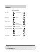
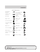
Introduction These are some of the symbols you may see on your vehicle.
Introduction Vehicle Symbol Glossary Power Windows Front/Rear Power Window Lockout Child Safety Door Lock/Unlock Interior Luggage Compartment Release Symbol Panic Alarm Engine Oil Engine Coolant Engine Coolant Temperature Do Not Open When Hot Battery Avoid Smoking, Flames, or Sparks Battery Acid Explosive Gas Fan Warning Power Steering Fluid Maintain Correct Fluid Level Emission System Engine Air Filter Passenger Compartment Air Filter Jack Check fuel cap Low tire warning MAX MIN 9 R
Instrument Cluster Instrument Cluster WARNING LIGHTS AND CHIMES Warning lights and gauges can alert you to a vehicle condition that may become serious enough to cause expensive repairs. A warning light may illuminate when a problem exists with one of your vehicle’s functions. Many lights will illuminate when you start your vehicle to make sure the bulb works. If any light remains on after starting the vehicle, have the respective system inspected immediately.
Instrument Cluster Brake system warning light: To ! P confirm the brake system warning light is functional, it will BRAKE momentarily illuminate when the ignition is turned to the ON position when the engine is not running, or in a position between ON and START, or by applying the parking brake when the ignition is turned to the ON position. If the brake system warning light does not illuminate at this time, seek service immediately from your dealership.
Instrument Cluster Engine oil pressure: Illuminates when the oil pressure falls below the normal range, refer to Engine oil in the Maintenance and Specifications chapter. Traction Control娂 active (if equipped): Flashes when the Traction Control娂 is active. If the light remains on a malfunction has been detected; have the system serviced immediately, refer to the Driving chapter for more information. Speed control: Illuminates when CRUISE the speed control is activated.
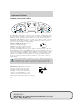
Instrument Cluster GAUGES Speedometer: Indicates the current vehicle speed. Engine coolant temperature gauge: Indicates engine coolant temperature. At normal operating temperature, the needle will be in the normal range (between “H” and “C”). If it enters the red section, the engine is overheating. Stop the vehicle as soon as safely possible, switch off the engine and let the engine cool. Never remove the coolant reservoir cap while the engine is running or hot.
Instrument Cluster Tachometer: Indicates the engine speed in revolutions per minute. Driving with your tachometer pointer continuously at the top of the scale may damage the engine. Fuel gauge: Indicates approximately how much fuel is left in the fuel tank (when the ignition is in the ON position). The fuel gauge may vary slightly when the vehicle is in motion or on a grade. The FUEL icon and arrow indicates which side of the vehicle the fuel filler door is located.
Entertainment Systems Entertainment Systems AM/FM STEREO CASSETTE/MACH姞 AUDIO SYSTEM WITH AM/FM STEREO CASSETTE (IF EQUIPPED) 1. Tape: Insert the cassette with the opening to the right. If a tape is already inserted into the system, press TAPE to begin tape play. 2. Clock: To set the hour, press and hold the H control. When the desired hour appears, release the control. To set the minute, press and hold the M control. When the desired minute appears, release the control. 3.
Entertainment Systems 6. Balance: Press / to shift sound to the left/right speakers. / to shift 7. Fade: Press sound to the rear/front speakers. BAL FADE 8. Scan: Press SCAN to hear a brief sampling of all listenable radio stations, tape or CD selections. Press again to stop. 9. Shuffle: Press to play CD tracks in random order. 10. COMP (compression): While playing a CD, press to bring soft and loud passages together for a more consistent listening level. Dolby威 noise reduction: 11.
Entertainment Systems 16. Tune: Works in radio mode or / to change CD mode. Press frequency down/up or previous/next disc. 17. Cassette door: Insert a cassette into the cassette door. 18. Seek: Press and / for previous/next release listenable radio station, tape selection or CD track. 19. Power/volume: Press to turn ON/OFF; turn to increase or decrease volume levels. 20. AM/FM: Press to choose a frequency band in radio mode (AM/FM1/FM2). VOL PUSH ON AM FM 21. EJ (Eject): Press to eject a tape.
Entertainment Systems AUDIO SYSTEM WITH AM/FM STEREO/SINGLE CD PLAYER (IF EQUIPPED) 16 3 2 1 17 15 4 14 5 13 12 11 10 9 8 7 6 1. Clock: To set the hour, press and hold the H control. When the desired hour appears, release the control. To set the minute, press and hold the M control. When the desired minute appears, release the control. / to 2. Bass: Press decrease/increase the bass output. / to 3. Treble: Press decrease/increase the treble output. / to shift 4.
Entertainment Systems 6. Scan: Press to hear a brief sampling of all listenable radio stations or CD tracks. Press again to stop. 7. CD: Press to play a CD. Press again to toggle between single CD mode and CD Changer mode (if equipped). 8. Shuffle: Press to play CD tracks in random order. 9. COMP (compression): Press to bring soft and loud passages together for a more consistent listening level. 10. FF (fast forward): Press and hold until desired selection is reached. 11.
Entertainment Systems 16. EJ (Eject): Press to eject a CD. 17. AM/FM: Press to choose a frequency band (AM/FM1/FM2). AM FM CD CHANGER (IF EQUIPPED) Your CD changer is either located in the trunk, the center console or the right side cargo area storage compartment (wagon only). 1. Slide the door to access the CD changer magazine. 2. Press to eject the magazine. 3. Turn the magazine (A) over. 4. Using the disc holder release knob (C), pull the disc holder (B) out of the magazine.
Entertainment Systems 5. Line up the CD with the groove of the disc holder. Ensure that the label on the CD faces downwards. 6. Press the disc holder until it locks securely into the magazine. Ensure that the disc holder is evenly inserted and at the same level as the magazine (A). The unit will not operate if the disc holder is not inserted at the same level (B).
Entertainment Systems • Tighten very loose tapes by inserting a finger or pencil into the hole and turning the hub. • Remove loose labels before inserting tapes. • Allow tapes which have been subjected to extreme heat, humidity or cold to reach a moderate temperature before playing. • Clean the cassette player head with a cassette cleaning cartridge after 10–12 hours of play to maintain good sound/operation. Don’t: • Expose tapes to direct sunlight, extreme humidity, heat or cold.
Climate Controls Climate Controls MANUAL HEATING AND AIR CONDITIONING SYSTEM (IF EQUIPPED) 1. Temperature selection: Controls the temperature of the airflow in the vehicle. 2. Passenger airbag indicator light: Indicates whether the Passenger front air bag is currently ON or OFF. Refer to Front passenger sensing system in the Seating and Safety Restraints chapter. 3. Air flow selections: Controls the direction of the airflow in the vehicle. See the following for a brief description on each control.
Climate Controls OPERATING TIPS • To reduce fog build up on the windshield during humid weather, place position. the air flow selector in the • To reduce humidity buildup within the cabin, do not drive with the selector in the OFF or MAX A/C position. • To improve A/C cool down, drive with the windows slightly open for the first 2–3 minutes after starting the vehicle or until the vehicle has “aired out.” • Do not put objects under the front seats that will interfere with the airflow to the back seats.
Climate Controls AUTOMATIC TEMPERATURE CONTROL SYSTEM (IF EQUIPPED) 10 11 F 2 1 12 13 14 A/C OFF R AUTO 9 8 7 6 PASS AIRBAG OFF TEMP 5 4 3 1. OFF: Outside air is shut out and the climate control system is turned off. 2. A/C: Press to activate/deactivate air conditioning. Use with the recirculated air to improve cooling performance and efficiency. Engages (defrost) and (floor/defrost) automatically in the AUTO, F modes. 3.
Climate Controls 6. AUTO: Press to engage full automatic operation, and select the desired temperature using the temperature control. The system will automatically determine fan speed, airflow location, A/C on or off, and outside or recirculated air, to heat or cool the vehicle to reach the desired temperature. 7. Fan Speed: Press to manually increase/decrease fan speed. To return to automatic fan operation, select AUTO. 8. Manual override controls: Allows you to change the system operation.
Climate Controls OPERATING TIPS • To reduce fog build up on the windshield during humid weather, place position. the air flow selector in the • To reduce humidity build up inside the vehicle, do notdrive with the (recirculated air) airflow selector in the OFF position, or with engaged without A/C engaged as well. • Do not put objects under the front seats that will interfere with the airflow to the back seats. • Remove any snow, ice or leaves from the air intake area at the base of the windshield.
Climate Controls REAR WINDOW DEFROSTER The rear defroster control is located on the instrument panel. Press the rear defroster control to clear the rear window of thin ice R and fog. • A small LED will illuminate when the rear defroster is activated. The ignition must be in the ON position to operate the rear window defroster. The defroster turns off automatically after 10 minutes or when the ignition is turned to the OFF position.
Lights Lights HEADLAMP CONTROL Turns the lamps off. Turns on the parking lamps, instrument panel lamps, license plate lamps and tail lamps. Turns the headlamps on. Autolamp control (if equipped) The autolamp system provides light sensitive automatic on-off control of the exterior lights normally controlled by the headlamp control. The autolamp system also keeps the lights on for a fixed period of time after the ignition switch is turned to OFF. • To turn autolamps on, rotate the control counterclockwise.
Lights Daytime running lamps (DRL) (if equipped) Turns the headlamps on with a reduced output. To activate: • the ignition must be in the ON position, • the headlamp control is in the OFF or parking lamp position and • the parking brake must be disengaged. Always remember to turn on your headlamps at dusk or during inclement weather. The Daytime Running Lamp (DRL) system does not activate the tail lamps and generally may not provide adequate lighting during these conditions.
Lights PANEL DIMMER CONTROL Use to adjust the brightness of the instrument panel and all applicable switches in the vehicle during headlamp and parklamp operation. Move the control to the full upright position, past detent, to turn on the interior lamps. A AIMING THE HEADLAMPS The headlamps on your vehicle are properly aimed at the assembly plant. If your vehicle has been in an accident the alignment of your headlamps should be checked by a qualified service technician. Vertical aim adjustment 1.
Lights 4. On the wall or screen you will observe an area of high intensity light. The top of the high intensity area should touch the horizontal reference line, if not, the beam will need to be adjusted. To see a clearer light pattern for adjusting, you may want to block the light from one headlamp while adjusting the other. 5. Locate the vertical adjuster on each headlamp. Using a 4 mm wrench, turn the adjuster either clockwise (to adjust down) or counterclockwise (to adjust up).
Lights INTERIOR LAMPS Map lamps/dome lamp (without moon roof) The map lamp controls are located on the dome lamp. Press the controls on either side of each lens on each map lamp to activate the lamps. The dome lamp will illuminate whenever a front door is opened. If either front door has been opened from the outside, the lamp will remain on for 25 seconds after the door is shut. If any other door has been opened from the inside, the lamp will shut off immediately after the door is closed.
Lights Map lamps (with moon roof) The map lamps are located on the moon roof control panel. Press the controls on either side of each map lamp to activate the lamps. Rear dome lamp (wagon only) The dome lamp lights when: • any door is opened with the control in the middle position. • the instrument panel dimmer switch is held up until the courtesy lamps come on. • any of the remote entry controls are pressed and the ignition is OFF. • the lamp control is moved to the passenger side position.
Lights Using the right bulbs Replacement bulbs are specified in the chart below. Headlamp bulbs must be marked with an authorized “D.O.T.” for North America and an “E” for Europe to assure lamp performance, light brightness and pattern and safe visibility. The correct bulbs will not damage the lamp assembly or void the lamp assembly warranty and will provide quality bulb burn time.
Lights Replacing headlamp bulbs To remove the headlamp bulb: 1. Make sure headlamp switch is in OFF position and open the hood. 2. Remove the bolt (1) from the headlamp housing. 3. At the back of the headlamp, pry up and remove the two retainer pins to release the headlamp assembly from the vehicle and pull headlamp forward. 4. Remove the protective dust shield from the housing by turning the dust shield counterclockwise (when viewed from the rear).
Lights 5. Disconnect the electrical connector from the bulb by pulling rearward. 6. Remove the bulb retaining ring by rotating it counterclockwise. 7. Remove the old bulb from the lamp assembly by pulling it straight out of the lamp assembly. To install the new bulb: Handle a halogen headlamp bulb carefully and keep out of children’s reach. Grasp the bulb only by its plastic base and do not touch the glass. The oil from your hand could cause the bulb to break the next time the headlamps are operated. 1.
Lights 2. Install the bulb retaining ring over the plastic base and lock the ring by rotating clockwise until it snaps into place. 3. Connect the electrical connector to the bulb. 4. Install the protective dust shield and lock the shield by rotating it clockwise until it locks into position. 5. Carefully position the headlamp assembly onto the vehicle. 6. Hold the headlamp assembly snugly against the vehicle and install the retainer pins straight down to lock the lamp into place. 7.
Lights 5. Carefully pull bulb straight out of the socket and push in the new bulb. 6. Install the bulb socket into the lamp assembly by rotating it clockwise. 7. Carefully position the headlamp assembly onto the vehicle. 8. Hold the headlamp assembly snugly against the vehicle and install the retainer pins straight down to lock the lamp into place. 9. Before reinstalling the bolt, make sure the retainer pins are fully seated, and install bolt on headlamp housing. 10.
Lights Replacing high-mount brakelamp bulbs — Wagon only 1. Open liftgate. 2. Remove two screw covers, screws and handle from liftgate. 3. Remove two screws and the lower trim panel from the liftgate. 4. Remove the upper trim panel. 5. Remove the rubber plug from the lower access hole in the upper portion of the liftgate. 6. Remove four nuts from the lamp assembly.
Lights 7. Carefully lift the lamp assembly away from the liftgate. 8. Remove the bulb socket by rotating it counterclockwise and pulling it out from the lamp assembly. 9. Carefully pull the bulb straight out of the socket and push in the new bulb. 10. To complete installation, follow the removal procedure in reverse order.
Lights Replacing license plate lamp bulbs Wagon 1. Make sure headlamp switch is in OFF position and remove screw and the license plate lamp assembly from liftgate. 2. Remove bulb socket by turning counterclockwise. 3. Carefully pull the bulb out from the socket and push in the new bulb. 4. Install the lamp assembly on liftgate with screw. Sedan 1. Make sure headlamp switch is in OFF position and remove two screws, grommets and the license plate lamp assembly from the trunk lid. 2.
Lights Replacing tail/brake/turn signal/backup lamp bulbs Sedan The tail lamp, brake lamp, turn signal lamp and backup lamp bulbs are located in the same portion of the tail lamp assembly. Follow the same steps to replace either bulb. 1. Make sure headlamp switch is in OFF position and open trunk and remove two plastic mushroom nuts, three push pins and the plastic cover from inside the trunk to access the lamp assembly. 2. Carefully pull the carpet away to expose the lamp assembly hardware. 3.
Lights Wagon The tail lamp/turn lamp/brake lamp/backup bulbs are located in the same portion of the tail lamp assembly, one just below the other. Follow the same steps to replace either bulb: 1. Make sure headlamp switch is in OFF position and open the liftgate to expose the lamp assemblies. 2. Remove the two bolts from the tail lamp assembly. 3. Carefully pull the lamp assembly outwards from the body side panel.
Driver Controls Driver Controls MULTI-FUNCTION LEVER Windshield wiper: Rotate the end of the control away from you to increase the speed of the wipers; rotate towards you to decrease the speed of the wipers. Windshield washer: Push the end of the stalk: • briefly: causes a single swipe of the wipers without washer fluid. • a quick push and hold: the wipers will swipe three times with washer fluid. • a long push and hold: the wipers and washer fluid will be activated for up to ten seconds.
Driver Controls Press the washer control to activate the rear washer. The wiper will come on when the washer control is pressed, if it is not already on. Changing the wiper blades 1. Pull the wiper arm away from the vehicle. Turn the blade at an angle from the wiper arm. Push the lock pin manually to release the blade and pull the wiper blade down toward the windshield to remove it from the arm. 2. Attach the new wiper to the wiper arm and press it into place until a click is heard. 3.
Driver Controls TILT STEERING WHEEL To adjust the steering wheel: 1. Pull and hold the steering wheel release control toward you. 2. Move the steering wheel up or down until you find the desired location. 3. Release the steering wheel release control. This will lock the steering wheel in position. Never adjust the steering wheel when the vehicle is moving. ILLUMINATED VISOR MIRROR (IF EQUIPPED) Lift the mirror cover to turn on the visor mirror lamp.
Driver Controls The auxiliary power point is located on the instrument panel below the optional cigarette lighter (if equipped). POWER WINDOWS Do not leave children unattended in the vehicle and do not let children play with the power windows. They may seriously injure themselves. When closing the power windows, you should verify they are free of obstructions and ensure that children and/or pets are not in the proximity of the window openings.
Driver Controls Accessory delay With accessory delay, the window switches may be used for up to ten minutes after the ignition switch is turned to the OFF position or until any door is opened. MIRRORS Automatic dimming inside rear view mirror (if equipped) Your vehicle may be equipped with an inside rear view mirror with an auto-dimming function. The electronic day/night mirror will change from the normal (high reflective) state to the non-glare (darkened) state when bright lights (glare) reach the mirror.
Driver Controls Heated outside mirrors (if equipped) Both mirrors are heated automatically to remove ice, mist and fog when the rear window defrost is activated. Do not remove ice from the mirrors with a scraper or attempt to readjust the mirror glass if it is frozen in place. These actions could cause damage to the glass and mirrors. SPEED CONTROL With speed control set, you can maintain a speed of 30 mph (48 km/h) or more without keeping your foot on the accelerator pedal.
Driver Controls Note: • Vehicle speed may vary momentarily when driving up and down a steep hill. • If the vehicle speed increases above the set speed on a downhill, you may want to apply the brakes to reduce the speed. • If the vehicle speed decreases more than 10 mph (16 km/h) below your set speed on an uphill, your speed control will disengage.
Driver Controls Reducing speed while using speed control There are three ways to reduce a set speed: • Press and hold the CST control until you get to the desired speed, then release the control. • Press and release the CST control to operate the Tap-Down function. Each tap will decrease the set speed by 1 mph (1.6 km/h). • Depress the brake pedal until the desired vehicle speed is reached, press the SET ACC control.
Driver Controls MOON ROOF (IF EQUIPPED) You can move the glass panel of the moon roof back to open or tilt up to ventilate the vehicle. To open the moon roof: The moon roof is equipped with an automatic, one-touch, express opening feature. Press and release the rear portion of the control. To close: Press and hold the front portion of the control. To vent: To tilt the moon roof into the vent position (when the glass panel is closed), press and hold the front portion of the control.
Driver Controls Do not use the HomeLink威 Wireless Control System with any garage door opener that lacks safety stop and reverse features as required by U.S. federal safety standards (this includes any garage door opener model manufactured before April 1, 1982). A garage door which cannot detect an object, signaling the door to stop and reverse, does not meet current U.S. federal safety standards. For more information, contact HomeLink威 at: www.homelink.com or 1–800–355–3515.
Driver Controls 3. Simultaneously press and hold both the HomeLink威 and hand-held transmitter button. Do not release the buttons until Step 4 has been completed. Some entry gates and garage door openers may require you to replace Step 3 with procedures noted in the “Gate Operator and Canadian Programming” in this section for Canadian residents. 4. The indicator light will flash slowly and then rapidly. Release both buttons when the indicator light flashes rapidly.
Driver Controls Gate Operator & Canadian Programming During programming, your hand-held transmitter may automatically stop transmitting — not allowing enough time for HomeLink威 to accept the signal from the hand-held transmitter. After completing steps 1 and 2 outlined in the “Programming” section, replace Step 3 with the following: Note: If programming a garage door opener or gate operator, it is advised to unplug the device during the “cycling” process to prevent overheating.
Driver Controls Erasing HomeLink姞 buttons To erase the three programmed buttons (individual buttons cannot be erased): • Press and hold the two outer HomeLink威 buttons until the indicator light begins to flash-after 20 seconds. Release both buttons. Do not hold for longer that 30 seconds. HomeLink威 is now in the train (or learning) mode and can be programmed at any time beginning with Step 2 in the “Programming” section.
Driver Controls Info menu This control displays the following control displays: • Odometer • Distance to Empty • Average Fuel Economy • Trip odometer • Trip Elapsed Drive Time • Outside air temperature (if equipped) • Compass (if equipped) Odometer/Trip odometer Refer to Gauges in the Instrument Cluster chapter. Distance to empty (DTE) Selecting this function from the INFO menu estimates approximately how far you can drive with the fuel remaining in your tank under normal driving conditions.
Driver Controls Average fuel economy (AFE) Select this function from the INFO menu to display your average fuel economy in liters/100 km or miles/U.S. gallon.
Driver Controls Outside air temperature (if equipped) Press and hold the INFO button for 2 seconds to display the outside temperature. To switch from a blank display to the temperature display, hold the INFO button for 2 seconds until the temperature is seen in the display. To switch the temperature display to compass display, hold the INFO button again for 2 seconds until the compass heading is seen in the display To turn the display off or change the display from English to metric see your dealer.
Driver Controls 2. Start the engine. 3. Press and hold the INFO button for 2 seconds to select the Compass/Odometer function. (Do not select Trip, DTE, or AFE. The top of the message center must be blank). Note: If the compass displays ⬙CAL 000000.0 mi⬙ instead of heading information, the compass will need to be calibrated. Slowly drive the vehicle in a circle (less than 3 mph [5 km/h]) until the ⬙CAL⬙ indicator changes to display compass heading. This may take up to 3 circles to complete calibration. 4.
Driver Controls 9. Slowly drive the vehicle in a circle (less than 3 mph [5 km/h]) until the CIRCLE SLOWLY TO CALIBRATE indicator changes to CALIBRATION COMPLETED. This will take up to three circles to complete calibration. 10. The compass is now calibrated. Setup menu Press this control for the following displays: • Language • Units (English/Metric) • System Check Language 1. Select this function from the SETUP menu for the current language to be displayed. 2.
Driver Controls Units (English/Metric) 1. Select this function from the SETUP menu for the current units to be displayed. 2. Press the RESET control to change from English to Metric. System check Selecting this function from the SETUP menu causes the message center to cycle through each of the systems being monitored. For each of the monitored systems, the message center will indicate either an OK message or a warning message for two to four seconds.
Driver Controls Warning messages that have been reset are divided into three categories: • They will not disappear until a condition is changed. • They will reappear on the display ten minutes from the reset. • They will not reappear until an ignition OFF-ON cycle has been completed. This acts as a reminder that these warning conditions still exist within the vehicle.
Driver Controls PARK BRAKE ENGAGED. Displayed when the park brake is engaged. If the warning stays on after the park brake is off, contact your dealer as soon as possible. CHECK ENGINE TEMPERATURE. Displayed when the engine coolant is overheating. Stop the vehicle as soon as safely possible, turn off the engine and let it cool. Check the coolant and coolant level. Refer to Engine coolant in the Maintenance and Specifications chapter.
Driver Controls LIFTGATE AJAR (if equipped). Displayed when the liftgate is not completely closed. CHECK TRACTION CONTROL (if equipped). Displayed when the Traction Control娂 system is not operating properly. If this warning stays on, contact your dealer for service as soon as possible. For further information, refer to Traction control娂 in the Driving chapter. DATA ERR. These messages indicate improper operation of the vehicle network communication between electronic modules.
Driver Controls • Rear ashtray (see your Ford, Lincoln Mercury dealer to obtain rear ashtray Use only soft cups in the cupholder. Hard objects can injure you in a collision. If your vehicle is equipped with the column shift and a bench seat, it has a center console in the center front seating position. The center console has similar features as the full console. To open the storage compartment, raise the armrest and pull the strap on the seat up and toward the front of the vehicle.
Driver Controls POSITIVE RETENTION FLOOR MAT Position the driver floor mat so that the eyelet is over the pointed end of the retention post and rotate forward to lock in. Make sure that the mat does not interfere with the operation of the accelerator or the brake pedal. To remove the floor mat, reverse the installation procedure. INTERIOR TRUNK CONTROL (SEDANS) Press the remote trunk release control on the instrument panel to the left of the steering wheel.
Driver Controls The liftgate and liftgate window should be closed before driving your vehicle. If not, possible damage may occur to the liftgate lift cylinders and attaching hardware. CARGO AREA FEATURES Storage compartment (Wagon) Your vehicle comes equipped with a storage compartment in the floor of the cargo area. An additional compartment is in the rear trim panel on the right. Always put the load you are carrying as far forward as possible.
Driver Controls Do not place any objects on the cargo area cover. They may obstruct your vision or strike occupants of the vehicle in the case of a sudden stop or collision. The cover may cause injury in a sudden stop or accident if it is not securely installed. Rewinding the shade With extended use, the cargo shade may lose its spring tension. If this occurs, the shade must be manually rewound. This is a two-person operation. 1.
Driver Controls The cover may cause injury in a sudden stop or accident if it is not securely installed. Cargo utility hooks (Sedan) The utility hooks located inside the trunk can be used to attach a cargo net to secure lightweight objects or hang small items on. Do not hang more than 20 lbs (12 kg) on the hooks. The hooks are not designed to restrain objects during a collision. LUGGAGE RACK (IF EQUIPPED) (WAGON) The rear cross-bar can be adjusted to fit the item being carried.
Locks and Security Locks and Security KEYS The key operates all locks on your vehicle. In case of loss, replacement keys are available from your dealer. You should always carry a second key with you in a safe place in case you require it in an emergency. Refer to the SecuriLock娂 passive anti-theft system section in this chapter for more information. POWER DOOR LOCKS Press control to unlock or lock all doors.
Locks and Security 1. Turn the ignition to the 4 (ON) 3 position, then press the power door 2 UNLOCK control 3 times. 2. Turn the ignition to the 3 (OFF) 4 position, then press the power door 1 UNLOCK control 3 times. 5 3. Turn the ignition to the 4 (ON) position. The horn will chirp one time as confirmation that the programming mode is staged. 4. Within 5 seconds, press the power door UNLOCK control and then press the power door LOCK control.
Locks and Security INTERIOR LUGGAGE COMPARTMENT RELEASE Your vehicle is equipped with a mechanical interior luggage compartment release handle that provides a means of escape for children and adults in the event they become locked inside the luggage compartment. Adults are advised to familiarize themselves with the operation and location of the release handle. To open the luggage compartment door (lid) from within the luggage compartment, pull the illuminated “T” shaped handle and push up on the trunk lid.
Locks and Security REMOTE ENTRY SYSTEM (IF EQUIPPED) This device complies with part 15 of the FCC rules and with RS-210 of Industry Canada. Operation is subject to the following two conditions: (1) This device may not cause harmful interference, and (2) This device must accept any interference received, including interference that may cause undesired operation. Changes or modifications not expressly approved by the party responsible for compliance could void the user’s authority to operate the equipment.
Locks and Security The inside lights will not turn off if: • they have been turned on using the dimmer control or • any door is open. The battery saver feature will turn off the interior lamps 10 minutes after the ignition is turned to the 3 (OFF) position. Locking the doors 1. Press and release to lock all the doors and liftgate (wagon), turn off the interior lamps (if they were on) and arm the anti-theft system. Note: The parklamps will flash once if all doors and liftgate (wagon) are closed.
Locks and Security Replacing the battery The remote entry transmitter uses one coin type three-volt lithium battery CR2032 or equivalent. To replace the battery: 1. Twist a thin coin between the two halves of the remote entry transmitter near the key ring. DO NOT TAKE THE RUBBER COVER AND CIRCUIT BOARD OFF THE FRONT HOUSING OF THE REMOTE ENTRY TRANSMITTER. 2. Do not wipe off any grease on the battery terminals on the back surface of the circuit board. 3. Remove the old battery.
Locks and Security How to reprogram your remote entry transmitters You must have all remote entry transmitters (maximum of four) available before beginning this procedure. To reprogram the remote entry 3 transmitters: 2 1. Ensure the vehicle is electronically unlocked. 4 2. Put the key in the ignition. 1 5 3. Turn the key from the 2 (LOCK) position to 3 (OFF). 4. Cycle eight times rapidly (within 10 seconds) between the 3 (OFF) position and 4 (ON). Note: The eighth turn must end in the 4 (ON) position. 5.
Locks and Security The inside lights will not turn off if: • they have been turned on with the dimmer control, or • any door is open. The battery saver will shut off the interior lamps 10 minutes after the ignition has been turned to the 3 (OFF) position. Perimeter lamps illuminated entry The exterior lamps illuminate when the vehicle is unlocked using the remote entry system.
Locks and Security 4. Press the power door unlock control twice within 5 seconds. Note: The horn will chirp twice to indicate the perimeter lighting feature has been deactivated or activated 5. Turn the ignition to the 3 (OFF) position to exit the procedure. Note: The horn will chirp once to confirm the procedure is complete. Note: The puddle lamps (if equipped) cannot be deactivated; performing this procedure will only deactivate the head, park and tail lamps.
Locks and Security Erasing personal codes 1. Enter the factory set 5–digit code. The keyless entry keypad and interior lights will illuminate and the driver’s door will unlock. 2. Press and release the 1 • 2 within five seconds of completing Step 1. 3. Press and hold the 1 • 2 for two seconds to erase the customer programmed codes. All personal codes are now erased and only the factory set 5–digit code will work.
Locks and Security To deactivate/reactivate the autolock feature using the power door unlock control You must complete Steps 1-4 within 30 seconds or the procedure will have to be repeated. If the procedure needs to be repeated, you must wait 30 seconds. Note: All doors must be closed and remain closed throughout the process. 1. Turn the ignition to the 4 (ON) 3 position, then press the power door 2 UNLOCK control 3 times. 2.
Locks and Security objects will not cause damage to the coded key, but may cause a momentary issue if they are too close to the key when starting the engine. If a problem occurs, turn the ignition off, remove all objects on the key chain away from the coded key and restart the engine. Theft indicator The theft indicator is located in the instrument cluster.
Locks and Security Replacing coded keys can be very costly. Store an extra programmed key away from the vehicle in a safe place to help prevent any inconveniences. Please visit an authorized dealer to purchase additional spare or replacement keys. Programming spare keys You can program your own coded keys to your vehicle. Please read and understand the entire procedure before you begin. Tips: • A maximum of eight keys can be coded to your vehicle. • Only use Securilock娂 keys.
Locks and Security 9. Your new unprogrammed key is now programmed. If the key has been successfully programmed it will start the vehicle’s engine and the theft indicator light will illuminate for three seconds and then go out. If the key was not successfully programmed, it will not start your vehicle’s engine and the theft indicator light will flash on and off rapidly. If failure repeats, bring your vehicle to your dealer to have the new key(s) programmed.
Locks and Security Disarming the system You can disarm the system by any of the following actions: control on your remote entry • Unlock the doors by pressing the transmitter. • Unlock the doors by using the keyless entry pad. • Unlock the doors with a key. Turn the key full travel (toward the front of the vehicle) to ensure the alarm disarms. • Turn the ignition to the 4 (ON) position. control on the remote entry transmitter.
Seating and Safety Restraints Seating and Safety Restraints SEATING Notes: Reclining the seatback can cause an occupant to slide under the seat’s safety belt, resulting in severe personal injuries in the event of a collision. Do not pile cargo higher than the seatbacks to reduce the risk of injury in a collision or sudden stop. Adjustable head restraints (front seats) Head restraints help to limit head motion in the event of a rear collision. The front seats in your vehicle have adjustable head restraints.
Seating and Safety Restraints Using the manual lumbar support (if equipped) The lumbar control is located on the front of the seat cushion. Turn to adjust lumbar support. Adjusting the front manual seat (if equipped) Never adjust the driver’s seat or seatback when the vehicle is moving. Always drive and ride with your seatback upright and the lap belt snug and low across the hips. Lift handle to move seat forward or backward. Pull lever up to adjust seatback.
Seating and Safety Restraints Adjusting the front power seat (if equipped) The control is located on the outboard side of the seat cushion. Press to raise or lower the front portion of the seat cushion. Press to raise or lower the rear portion of the seat cushion. Press the control to move the seat forward, backward, up or down.
Seating and Safety Restraints REAR SEATS 2nd seat/split-folding rear seat (if equipped) Sedan Pull the loop forward to release the seatback and then fold the seatback down. Wagon Lift the latch on the rear of the seatback to release the seatback and then fold the seatback down. When raising the seatback(s), make sure you hear the seat latch into place. Make sure that the safety belt for the rear center passenger is properly routed over the rear seatback.
Seating and Safety Restraints 3rd seat (if equipped) (wagon only) The third seat faces the rear of the vehicle. For height and weight limits, see the label on the seat cushion. When the seat is down, the back of your wagon has a flat surface for carrying cargo. To open up the seat: 1. Unlock the floor panel with the key, then use the handle to fold the floor panel toward the front of the car. 2. Remove the cargo cover (if equipped).
Seating and Safety Restraints SAFETY RESTRAINTS Personal Safety System The Personal Safety System provides an improved overall level of frontal crash protection to front seat occupants and is designed to help further reduce the risk of air bag-related injuries. The system is able to analyze different occupant classifications and conditions and crash severity before activating the appropriate safety devices to help better protect a range of occupants in a variety of frontal crash situations.
Seating and Safety Restraints impacts or rear impacts) unless the collision causes sufficient longitudinal deceleration. The pretensioners are designed to activate in frontal and near-frontal collisions, and in side collisions when the vehicle is equipped with side air bags. Driver and passenger dual-stage air bag supplemental restraints The dual-stage air bags offer the capability to tailor the level of air bag inflation energy.
Seating and Safety Restraints Always transport children 12 years old and under in the back seat and always properly use appropriate child restraints. The front passenger sensing system can automatically turn off the passenger front air bag. The system is designed to help protect small (child size) occupants from air bag deployments when they are improperly seated or restrained in the front passenger seat contrary to proper child-seating or restraint usage recommendations.
Seating and Safety Restraints Determining if the Personal Safety System is operational The Personal Safety System uses a warning light in the instrument cluster or a back-up tone to indicate the condition of the system. Refer to the Warning Light section in the Instrument Cluster chapter. Routine maintenance of the Personal Safety System is not required.
Seating and Safety Restraints It is extremely dangerous to ride in a cargo area, inside or outside of a vehicle. In a collision, people riding in these areas are more likely to be seriously injured or killed. Do not allow people to ride in any area of your vehicle that is not equipped with seats and safety belts. Be sure everyone in your vehicle is in a seat and using a safety belt properly. In a rollover crash, an unbelted person is significantly more likely to die than a person wearing a seat belt.
Seating and Safety Restraints 2. To unfasten, push the release button and remove the tongue from the buckle. Energy management retractors Your vehicle has a seat belt system equipped with energy management retractors at the driver and front outboard passenger seating positions. An energy management retractor is a device which pays out webbing in a controlled manner. This feature is designed to help further reduce the risk of force-related injuries to the occupant.
Seating and Safety Restraints How to use the automatic locking mode • Buckle the combination lap and shoulder belt. • Grasp the shoulder portion and pull downward until the entire belt is pulled out. • Allow the belt to retract. As the belt retracts, you will hear a clicking sound. This indicates the safety belt is now in the automatic locking mode.
Seating and Safety Restraints After any vehicle collision, the seat belt system at all outboard seating positions (except driver, which has no “automatic locking retractor” feature) must be checked by a qualified technician to verify that the “automatic locking retractor” feature for child seats is still functioning properly. In addition, all seat belts should be checked for proper function.
Seating and Safety Restraints Safety belt usage sensors The driver and front outboard passenger safety belt buckles are equipped with sensors that detect if the safety belts are fastened. The sensors provide information to the Personal Safety System which can then adapt the air bag deployment or safety belt pretensioner activation based upon safety belt usage. The Personal Safety System provides the most benefit to belted occupants.
Seating and Safety Restraints Insert the tongue into the correct buckle (the buckle closest to the direction the tongue is coming from). To lengthen the belt, turn the tongue at a right angle to the belt and pull across your lap until it reaches the buckle. To tighten the belt, pull the loose end of the belt through the tongue until it fits snugly across the hips. Shorten and fasten the belt when not in use.
Seating and Safety Restraints To fasten the belt, pull the combination lap and shoulder belt from the retractor so that the shoulder belt portion of the safety belt crosses your shoulder and chest. Be sure the belt is not twisted. If the belt is twisted, remove the twist. Insert the tongue into the proper buckle for your seating position until you hear a snap and feel it latch. Make sure the tongue is securely fastened to the buckle by pulling on the tongue.
Seating and Safety Restraints Conditions of operation If... The driver’s safety belt is not buckled before the ignition switch is turned to the ON position... The driver’s safety belt is buckled while the indicator light is illuminated and the warning chime is sounding... The driver’s safety belt is buckled before the ignition switch is turned to the ON position... Then... The safety belt warning light illuminates 1-2 minutes and the warning chime sounds 4-8 seconds.
Seating and Safety Restraints If... The driver’s and front passenger’s safety belts are buckled before the ignition switch is turned to the ON position or less than 1-2 minutes have elapsed since the ignition switch has been turned ON... The driver’s or front passenger’s safety belt is not buckled when the vehicle has reached at least 3 mph (5 km/h) and 1-2 minutes have elapsed since the ignition switch has been turned to ON...
Seating and Safety Restraints The following are reasons most often given for not wearing safety belts (All statistics based on U.S. data): Reasons given... “Crashes are rare events” “I’m not going far” “Belts are uncomfortable” “I was in a hurry” “Safety belts don’t work” “Traffic is light” “Belts wrinkle my clothes” “The people I’m with don’t wear belts” Consider... 36700 crashes occur every day. The more we drive, the more we are exposed to “rare” events, even for good drivers.
Seating and Safety Restraints Reasons given... “I have an air bag” “I’d rather be thrown clear” Consider... Air bags offer greater protection when used with safety belts. Frontal airbags are not designed to inflate in rear and side crashes or rollovers. Not a good idea. People who are ejected are 40 times more likely to DIE. Safety belts help prevent ejection, WE CAN’T “PICK OUR CRASH”. Do not sit on top of a buckled safety belt to avoid the Belt Minder chime.
Seating and Safety Restraints Before following the procedure, make sure that: • The parking brake is set • The gearshift is in P (Park) (automatic transmission) • The ignition switch is in the OFF position • The driver and front passenger safety belts are unbuckled To reduce the risk of injury, do not deactivate/activate the Belt Minder feature while driving the vehicle. 1. Turn the ignition switch to the RUN (or ON) position. (DO NOT START THE ENGINE) 2. Wait until the safety belt warning light turns off.
Seating and Safety Restraints Do not use extensions to change the fit of the shoulder belt across the torso. Safety belt maintenance Inspect the safety belt systems periodically to make sure they work properly and are not damaged. Inspect the safety belts to make sure there are no nicks, tears or cuts. Replace if necessary.
Seating and Safety Restraints supplement to the safety belts. Air bags alone cannot protect as well as air bags plus safety belts in impacts for which the air bags are designed to deploy, and air bags do not offer any protection in crashes for which they do not deploy. The air bag supplemental restraint system consists of: • driver and passenger dual stage air bag modules (which include the inflators and air bags). • side air bags (if equipped). Refer to Side air bag system later in this chapter.
Seating and Safety Restraints Always transport children 12 years old and under in the back seat and always properly use appropriate child restraints. National Highway Traffic Safety Administration (NHTSA) recommends a minimum distance of at least 10 inches (25 cm) between an occupant’s chest and the driver air bag module. Never place your arm over the air bag module as a deploying air bag can result in serious arm fractures or other injuries.
Seating and Safety Restraints Children and air bags Children must always be properly restrained. Accident statistics suggest that children are safer when properly restrained in the rear seating positions than in the front seating position. Failure to follow these instructions may increase the risk of injury in a collision. Air bags can kill or injure a child in a child seat. NEVER place a rear-facing child seat in front of an active air bag.
Seating and Safety Restraints of air bag deployment. Thus, it is extremely important that occupants be properly restrained as far away from the air bag module as possible while maintaining vehicle control. Several air bag system components get hot after inflation. Do not touch them after inflation. If the air bag has deployed, the air bag will not function again and must be replaced immediately. If the air bag is not replaced, the unrepaired area will increase the risk of injury in a collision.
Seating and Safety Restraints Even with the front passenger sensing system, children 12 and under should be properly restrained in the back seat. When the front passenger seat is occupied and the sensing system has turned off the passenger’s frontal airbag, the ⬙passenger airbag off⬙ or ⬙pass airbag off⬙ indicator will light and stay lit to remind you that the front passenger frontal airbag is off.
Seating and Safety Restraints After all occupants have adjusted their seats and put on safety belts, it’s very important that they continue to sit upright with their back against the seatback, with their feet comfortably extended on the floor while the vehicle is still in motion. Sitting improperly can increase the chance of injury in a crash event.
Seating and Safety Restraints An out of position front center occupant could affect the decision of the front passenger sensing system. If it is necessary to modify an advanced front airbag system to accommodate a person with disabilities, contact the Ford Customer Relationship Center at the phone number shown in the Customer Assistance section of this Owners Guide. Any alteration/modification to the front passenger seat may affect the performance of the front passenger sensing system.
Seating and Safety Restraints Do not use accessory seat covers. The use of accessory seat covers may prevent the deployment of the side air bags and increase the risk of injury in an accident. Do not lean your head on the door. The side air bag could injure you as it deploys from the side of the seatback. Do not attempt to service, repair, or modify the air bag SRS, its fuses or the seat cover on a seat containing an air bag. See your Ford or Lincoln Mercury dealer.
Seating and Safety Restraints The air bag SRS is designed to activate when the vehicle sustains lateral deceleration sufficient to cause the sensors to close an electrical circuit that initiates air bag inflation. The fact that the air bags did not inflate in a collision does not mean that something is wrong with the system. Rather, it means the forces were not of the type sufficient to cause activation.
Seating and Safety Restraints require that children use approved booster seats until they are eight years old. Check your local and state or provincial laws for specific requirements regarding the safety of children in your vehicle. When possible, always place children under age 12 in the rear seat of your vehicle. Accident statistics suggest that children are safer when properly restrained in the rear seating positions than in the front seating position.
Seating and Safety Restraints Booster seats position a child so that safety belts fit better. They lift the child up so that the lap belt rests low across the hips and the knees bend comfortably. Booster seats also make the shoulder belt fit better and more comfortably for growing children. When children should use booster seats Children need to use booster seats from the time they outgrow the toddler seat until they are big enough for the vehicle seat and lap/shoulder belt to fit properly.
Seating and Safety Restraints • Those with a high back. If, with a backless booster seat, you cannot find a seating position that adequately supports your child’s head, a high back booster seat would be a better choice. Both can be used in any vehicle in a seating position equipped with lap/shoulder belts if your child is over 40 lb. (18 kg). The shoulder belt should cross the chest, resting snugly on the center of the shoulder.
Seating and Safety Restraints SAFETY SEATS FOR CHILDREN Child and infant or child safety seats Use a safety seat that is recommended for the size and weight of the child. Carefully follow all of the manufacturer’s instructions with the safety seat you put in your vehicle. If you do not install and use the safety seat properly, the child may be injured in a sudden stop or collision.
Seating and Safety Restraints Carefully follow all of the manufacturer’s instructions included with the safety seat you put in your vehicle. If you do not install and use the safety seat properly, the child may be injured in a sudden stop or collision. Rear-facing child seats or infant carriers should never be placed in the front seats. Installing child safety seats with combination lap and shoulder belts Air bags can kill or injure a child in a child seat.
Seating and Safety Restraints 2. Pull down on the shoulder belt and then grasp the shoulder belt and lap belt together. 3. While holding the shoulder and lap belt portions together, route the tongue through the child seat according to the child seat manufacturer’s instructions. Be sure the belt webbing is not twisted. 4. Insert the belt tongue into the proper buckle (the buckle closest to the direction the tongue is coming from) for that seating position until you hear a snap and feel the latch engage.
Seating and Safety Restraints 5. To put the retractor in the automatic locking mode, grasp the shoulder portion of the belt and pull downward until all of the belt is pulled out and a click is heard. 6. Allow the belt to retract. The belt will click as it retracts to indicate it is in the automatic locking mode. 7. Pull the lap belt portion across the child seat toward the buckle and pull up on the shoulder belt while pushing down with your knee on the child seat. 8.
Seating and Safety Restraints Installing child safety seats in the lap belt seating positions 1. Lengthen the lap belt. To lengthen the belt, hold the tongue so that its bottom is perpendicular to the direction of webbing while sliding the tongue up the webbing. 2. Place the child safety seat in the center seating position. 3. Route the tongue and webbing through the child seat according to the child seat manufacturer’s instructions. 4.
Seating and Safety Restraints 1. Position the child safety seat on the seat cushion. 2. Route the child safety seat tether strap over the back of the seat. For vehicles with adjustable head restraints, route the tether strap under the head restraint and between the head restraint posts, otherwise route the tether strap over the top of the seatback. 3. Locate the correct anchor for the selected seating position. • Sedan • Wagon 4. Open the tether anchor cover.
Seating and Safety Restraints On wagons, snap the tether anchor cover off the anchor under the load floor. 5. Clip the tether strap to the anchor as shown. • Sedan • Wagon If the tether strap is clipped incorrectly, the child safety seat may not be retained properly in the event of a collision. 6. Install the child safety seat tightly using the LATCH anchors or safety belts. Follow the instructions in this chapter. 7.
Seating and Safety Restraints If the safety seat is not anchored properly, the risk of a child being injured in a collision greatly increases. Attaching safety seats with LATCH (Lower Anchors and Tethers for Children) attachments for child seat anchors Some child safety seats have two rigid or webbing mounted attachments that connect to two anchors at certain seating positions in your vehicle. This type of child seat eliminates the need to use seat belts to attach the child seat.
Seating and Safety Restraints The lower anchors for child seat installation are located at the rear section of the rear seat between the cushion and seat back. The LATCH anchors are below the locator symbols on the seat back. Follow the child seat manufacturer’s instructions to properly install a child seat with LATCH attachments. Attach LATCH lower attachments of the child seat only to the anchors shown.
Tires, Wheels and Loading Tires, Wheels and Loading INFORMATION ABOUT UNIFORM TIRE QUALITY GRADING New vehicles are fitted with tires that have a rating on them called Tire Quality Grades. The Quality grades can be found where applicable on the tire sidewall between tread shoulder and maximum section width. For example: • Treadwear 200 Traction AA Temperature A These Tire Quality Grades are determined by standards that the United States Department of Transportation has set.
Tires, Wheels and Loading The traction grade assigned to this tire is based on straight-ahead braking traction tests, and does not include acceleration, cornering, hydroplaning or peak traction characteristics. Temperature A B C The temperature grades are A (the highest), B and C, representing the tire’s resistance to the generation of heat and its ability to dissipate heat when tested under controlled conditions on a specified indoor laboratory test wheel.
Tires, Wheels and Loading • Extra load: A class of P-metric or Metric tires designed to carry a heavier maximum load at 41 psi [43 psi (2.9 bar) for Metric tires]. Increasing the inflation pressure beyond this pressure will not increase the tire’s load carrying capability. • kPa: Kilopascal, a metric unit of air pressure. • PSI: Pounds per square inch, a standard unit of air pressure.
Tires, Wheels and Loading Inspecting your tires Periodically inspect the tire treads for uneven or excessive wear and remove stones, nails, glass or other objects that may be wedged in the tread grooves. Check for holes or cuts that may permit air leakage from the tire and make necessary repairs. Also inspect the tire sidewalls for cuts, bruises and other damage. If internal damage to the tire is suspected, have the tire demounted and inspected in case it needs to be repaired or replaced.
Tires, Wheels and Loading higher than the manufacturer’s recommended cold inflation pressure which can be found on either the tire label or certification label which is located on the B-Pillar or the edge of the driver’s door. The cold inflation pressure should never be set lower than the recommended pressure on the tire label or certification label. When weather temperature changes occur, tire inflation pressures also change.
Tires, Wheels and Loading TIRE REPLACEMENT REQUIREMENTS Your vehicle is equipped with tires designed to provide a safe ride and handling capability. Only use replacement tires and wheels that are the same size and type (such as P-metric versus LT-metric or all-season versus all-terrain) as those originally provided by Ford.
Tires, Wheels and Loading If you use the temporary spare tire continuously or do not follow these precautions, the tire could fail, causing you to lose control of the vehicle, possibly injuring yourself or others.
Tires, Wheels and Loading the road tires and wheels that were originally provided by Ford. If the dissimilar spare tire or wheel is damaged, it should be replaced rather than repaired.
Tires, Wheels and Loading To help prevent the vehicle from moving when you change a tire, be sure the parking brake is set, then block (in both directions) the wheel that is diagonally opposite (other side and end of the vehicle) to the tire being changed. If the vehicle slips off the jack, you or someone else could be seriously injured. 2. Place gearshift lever in P (Park), turn engine OFF, block the diagonally opposite wheel, then remove the spare tire, jack and lug wrench.
Tires, Wheels and Loading 3. If equipped with a wheel cover that’s bolted on, loosen the five plastic nuts with the lug nut wrench. 4. Remove the center ornament or wheel cover from the wheel with the tapered end of the wheel lug nut wrench that came with your vehicle. Insert and twist the handle, then pry against the wheel. 5. Loosen each wheel lug nut one-half turn counterclockwise but do not remove them until the wheel is raised off the ground. 6.
Tires, Wheels and Loading 10. Remove the jack and fully tighten the lug nuts in the order shown. Refer to Wheel lug nut torque specifications later in this chapter for the proper lug nut torque specification. 1 3 4 5 2 11. Return the flat tire, jack and lug wrench to their proper storage locations. Make sure the jack is fastened so it does not rattle when you drive. 12. Unblock the wheels.
Tires, Wheels and Loading When a wheel is installed, always remove any corrosion, dirt or foreign materials present on the mounting surfaces of the wheel or the surface of the front disc brake hub and rotor that contacts the wheel. Installing wheels without correct metal-to-metal contact at the wheel mounting surfaces can cause the wheel nuts to loosen and the wheel to come off while the vehicle is in motion, resulting in loss of control.
Tires, Wheels and Loading 5. 15: Indicates the wheel or rim diameter in inches. If you change your wheel size, you will have to purchase new tires to match the new wheel diameter. 6. 95: Indicates the tire’s load index. It is an index that relates to how much weight a tire can carry. You may find this information in your Owner’s Guide. If not, contact a local tire dealer. Note: You may not find this information on all tires because it is not required by federal law. 7. H: Indicates the tire’s speed rating.
Tires, Wheels and Loading numbers represent the week and year the tire was built. For example, the numbers 317 mean the 31st week of 1997. After 2000 the numbers go to four digits. For example, 2501 means the 25th week of 2001. The numbers in between are identification codes used for traceability. This information is used to contact customers if a tire defect requires a recall. 9. M+S or M/S: Mud and Snow, or AT: All Terrain, or AS: All Season. 10.
Tires, Wheels and Loading Additional information contained on the tire sidewall for “LT” type tires “LT” type tires have some additional information beyond those of “P” type tires; these differences are described below: 1. LT: Indicates a tire, designated by the Tire and Rim Association (T&RA), that is intended for service on light trucks. 2. Load Range/Load Inflation Limits: Indicates the tire’s load-carrying capabilities and its inflation limits. 3. Maximum Load Dual lb.
Tires, Wheels and Loading Information on “T” type tires “T” type tires have some additional information beyond those of “P” type tires; these differences are described below: T145/80D16 is an example of a tire size. Note: The temporary tire size for your vehicle may be different from this example. 1. T: Indicates a type of tire, designated by the Tire and Rim Association (T&RA), that is intended for temporary service on cars, SUVs, minivans and light trucks. 2.
Tires, Wheels and Loading TIRE CARE Improper or inadequate vehicle maintenance can also cause tires to wear abnormally. Here are some of the important maintenance items: Tire wear Measure and inspect the tire tread on all your tires periodically. Advanced and unusual tire wear can reduce the ability of tread to grip the road in adverse (wet, snowy, etc.) conditions. Visually check your tires for uneven wear, looking for high and low areas or unusually smooth areas. Also check for signs of tire damage.
Tires, Wheels and Loading Safety practices Driving habits have a great deal to do with your tire mileage and safety. • Observe posted speed limits • Avoid fast starts, stops and turns • Avoid potholes and objects on the road • Do not run over curbs or hit the tire against a curb when parking If your vehicle is stuck in snow, mud, sand, etc., do not rapidly spin the tires; spinning the tires can tear the tire and cause an explosion. A tire can explode in as little as three to five seconds.
Tires, Wheels and Loading The tires should also be balanced periodically. An unbalanced tire and wheel assembly may result in irregular tire wear. Tire rotation Rotating your tires at the recommended interval (as indicated in the Scheduled Maintenance Guide that comes with your vehicle) will help your tires wear more evenly, providing better tire performance and longer tire life. Unless otherwise specified, rotate the tires approximately every 5,000 miles (8,000 km).
Tires, Wheels and Loading • Rear Wheel Drive (RWD) vehicles/Four Wheel Drive (4WD)/ All Wheel Drive (AWD) vehicles (front tires at top of diagram) Sometimes irregular tire wear can be corrected by rotating the tires. Note: If your tires show uneven wear ask a qualified technician at a Ford or Lincoln/Mercury dealership to check for and correct any wheel misalignment, tire imbalance or mechanical problem involved before tire rotation. Note: Your vehicle may be equipped with a dissimilar spare tire/wheel.
Tires, Wheels and Loading SNOW TIRES AND CHAINS Snow tires must be the same size and grade as the tires you currently have on your vehicle. The tires on your vehicle have all weather treads to provide traction in rain and snow. However, in some climates, you may need to use snow tires and chains. If you need to use snow tires and chains, it is recommended that steel wheels are used of the same size and specifications as those originally installed.
Tires, Wheels and Loading Vehicle Curb Weight – is the weight of your new vehicle when you picked it up from your dealer plus any aftermarket equipment. Payload – is the combined weight of cargo and passengers that the vehicle is carrying. The maximum payload for your vehicle can be found on the Tire Label on the B-Pillar or the edge of the driver’s door. Look for “THE COMBINED WEIGHT OF OCCUPANTS AND CARGO SHOULD NEVER EXCEED XXX kg OR XXX lb.” for maximum payload.
Tires, Wheels and Loading Example only: Cargo Weight – includes all weight added to the Base Curb Weight, including cargo and optional equipment. When towing, trailer tongue load or king pin weight is also part of cargo weight.
Tires, Wheels and Loading GAW (Gross Axle Weight) – is the total weight placed on each axle (front and rear) – including vehicle curb weight and all payload. GAWR (Gross Axle Weight Rating) – is the maximum allowable weight that can be carried by a single axle (front or rear). These numbers are shown on the Safety Compliance Certification Label located on the driver’s door or B-Pillar. The total load on each axle must never exceed its GAWR.
Tires, Wheels and Loading GVWR (Gross Vehicle Weight Rating) – is the maximum allowable weight of the fully loaded vehicle (including all options, equipment, passengers and cargo). The GVWR is shown on the Safety Compliance Certification Label located on the driver’s door or B-Pillar. The GVW must never exceed the GVWR.
Tires, Wheels and Loading Maximum Loaded Trailer Weight – is the highest possible weight of a fully loaded trailer the vehicle can tow. It assumes a vehicle with only mandatory options, no cargo (internal or external), a tongue load of 10–15% (conventional trailer) or king pin weight of 15–25% (fifth wheel trailer), and driver only (150 lb. [68 kg]). Consult your dealership (or the RV and Trailer Towing Guide provided by your dealership) for more detailed information.
Tires, Wheels and Loading The following gives you a few examples on how to calculate the available amount of cargo and luggage load capacity: • An example for your vehicle with 1400 lbs. (636 kg) of cargo and luggage capacity. You decide to go golfing. You and your friends average 220 lbs. (100 kg) each and the golf bags weigh approximately 30 lbs. (14 kg) each.
Tires, Wheels and Loading Towing a trailer places an additional load on your vehicle’s engine, transaxle, brakes, tires and suspension. Inspect these components carefully after towing. The amount of weight that you can tow depends on the type of engine in your vehicle. See the following charts: Model Sedan Wagon 3.0L Engine Passenger Luggage Load - Max Trailer Load - #/lb. lb. (kg) Wt.- lb.
Tires, Wheels and Loading Safety chains Always connect the trailer’s safety chains to the frame or hook retainers of the vehicle hitch. To connect the trailer’s safety chains, cross the chains under the trailer tongue and allow slack for turning corners. If you use a rental trailer, follow the instructions that the rental agency gives to you. Do not attach safety chains to the bumper.
Tires, Wheels and Loading Trailer towing tips • Practice turning, stopping and backing up before starting on a trip to get the feel of the vehicle trailer combination. When turning, make wider turns so the trailer wheels will clear curbs and other obstacles. • Allow more distance for stopping with a trailer attached. • If you are driving down a long or steep hill, shift to a lower gear. Do not apply the brakes continuously, as they may overheat and become less effective.
Driving Driving STARTING Positions of the ignition 1. ACCESSORY, allows the electrical 3 accessories such as the radio to 2 operate while the engine is not running. 2. LOCK, locks the automatic transmission gearshift lever and 4 1 allows key removal. 5 3. OFF, shuts off the engine without locking the steering wheel. This position also allows the automatic transmission shift lever to be moved from the P (Park) position without the brake pedal being depressed.
Driving Extended idling at high engine speeds can produce very high temperatures in the engine and exhaust system, creating the risk of fire or other damage. Do not park, idle, or drive your vehicle in dry grass or other dry ground cover. The emission system heats up the engine compartment and exhaust system, which can start a fire. Do not start your vehicle in a closed garage or in other enclosed areas. Exhaust fumes can be toxic. Always open the garage door before you start the engine.
Driving 2. Make sure the headlamps and electrical accessories are off. • Make sure the parking brake is set. • Make sure the gearshift is in P (Park). P • Turn the key to 4 (ON) without turning the key to 5 (START).
Driving Make sure the corresponding lights illuminate or illuminate briefly. If a light fails to illuminate, have the vehicle serviced. • If the driver’s safety belt is fastened, the light may not illuminate. Starting the engine 1. Turn the key to 4 (ON) without 3 turning the key to 5(START). 2 2. Turn the key to 5 (START), then release the key as soon as the 4 engine starts. Excessive cranking 1 could damage the starter.
Driving If the engine fails to start using the preceding instructions (flexible fuel vehicles only) 1. Press and hold down the accelerator 1/3 to 1/2 way to floor, then crank the engine. 2. When the engine starts, release the key, then gradually release the accelerator pedal as the engine speeds up. If the engine still fails to start, repeat Step 1. Using the engine block heater (if equipped) An engine block heater warms the engine coolant which aids in starting and heater/defroster performance.
Driving when the brakes are applied. Such noises are usually heard during the first few brake applications in the morning; however, they may be heard at any time while braking and can be aggravated by environmental conditions such as cold, heat, moisture, road dust, salt or mud. If a “metal-to-metal,” “continuous grinding” or “continuous squeal” sound is present while braking, the brake linings may be worn-out and should be inspected by a qualified service technician.
Driving ABS warning lamp The ABS lamp in the instrument cluster momentarily illuminates ABS when the ignition is turned on. If the light does not illuminate during start up, remains on or flashes, the ABS may be disabled and may need to be serviced. Even when the ABS is disabled, ! P normal braking is still effective. (If your BRAKE warning lamp BRAKE illuminates with the parking brake released, have your brake system serviced immediately.
Driving TRACTION CONTROL姟 (IF EQUIPPED) Your vehicle may be equipped with a Traction Control娂 system. This system helps you maintain the stability and steerability of your vehicle, especially on slippery road surfaces such as snow- or ice-covered roads and gravel roads. The system will allow your vehicle to make better use of available traction in these conditions.
Driving STEERING To prevent damage to the power steering system, never hold the steering wheel at its furthest turning points (until it stops) for more than a few seconds when the engine is running. It is also important to maintain a proper power steering fluid level in the power steering fluid reservoir: • Do not operate the vehicle with a low power steering pump fluid level (below the MIN mark on the reservoir). • Some noise is normal during operation.
Driving When the key is in the ignition and in the OFF position, the automatic transmission shift lever can be moved from the P (Park) position without the brake pedal depressed. To avoid unwanted vehicle movement, always set the parking brake. 3. Start the vehicle. If it is necessary to use the above procedure to move the gearshift lever, it is possible that a fuse has blown or the vehicle’s brakelamps are not operating properly. Refer to Fuses and relays in the Roadside Emergencies chapter.
Driving If your vehicle is equipped with a console-mounted gearshift lever, you must press the thumb button on the side of the gearshift lever to move the gearshift lever from P (Park). To put your vehicle in gear, start the engine, depress the brake pedal, then move the gearshift lever out of P (Park). Hold the brake pedal down while you move the gearshift lever from P (Park) to another position. If you do not hold the brake pedal down, your vehicle may move unexpectedly and injure someone.
Driving parameters. This learning process could take several transmission upshifts and downshifts; during this learning process, slightly firmer shifts may occur. After this learning process, normal shift feel and shift scheduling will resume. P (Park) This position locks the transaxle and prevents the front wheels from turning.
Driving 1 (First) • Provides maximum engine braking. • Allows upshifts by moving gearshift lever. • Will not downshift into 1 (First) at high speeds; allows for 1 (First) when vehicle reaches slower speeds. When parking, do not use the gearshift in place of the parking brake. Always set the parking brake fully and make sure that the gearshift is securely latched in Park (P). Turn off the ignition whenever you leave your vehicle. Never leave your vehicle unattended while it is running.
Roadside Emergencies Roadside Emergencies GETTING ROADSIDE ASSISTANCE To fully assist you should you have a vehicle concern, Ford Motor Company offers a complimentary roadside assistance program. This program is separate from the New Vehicle Limited Warranty.
Roadside Emergencies Canadian customers who require roadside assistance, call 1–800–665–2006. If you need to arrange roadside assistance for yourself, Ford Motor Company will reimburse a reasonable amount. To obtain reimbursement information, U.S. Ford or Mercury vehicles customers call 1-800-241-3673; Lincoln vehicle customers call 1–800–521–4140. Canadian customers who need to obtain reimbursement information, call 1–800–665–2006.
Roadside Emergencies If your vehicle is a sedan, the fuel pump shut-off switch is located on the right side of the trunk behind the trunk liner. If your vehicle is a wagon, the fuel pump shut-off switch is located behind the service panel on the right side of the cargo area. Use the following procedure to reset the fuel pump shut-off switch. 1. Turn the ignition to the OFF position. 2. Check the fuel system for leaks. 3.
Roadside Emergencies FUSES If electrical components in the vehicle are not working, a fuse may have blown. Blown fuses are identified by a broken wire within the fuse. Check the appropriate fuses before replacing any electrical components. 15 Note: Always replace a fuse with one that has the specified amperage rating. Using a fuse with a higher amperage rating can cause severe wire damage and could start a fire.
Roadside Emergencies To remove a fuse use the fuse puller tool provided on the fuse panel cover. The fuses are coded as follows.
Roadside Emergencies Fuse/relay location 19 20 21 Fuse amp rating 10A 10A 15A 22 15A 23 24 25 26 30A — 20A 20A 27 10A 28 29 30 15A 20A 10A 31 10A 32 10A 33 15A 34 35 36 5A 10A 2A Passenger compartment fuse panel description Heated mirrors, Rear defrost switch indicator Restraints (air bag module/OCS module) Transmission range sensor (transmission position switch) Front washer pump, Electrochromatic mirror, Compass, Cluster (RUN/ACC), Integrated Control Panel (ICP) logic, Rear wiper (wagon
Roadside Emergencies Fuse/relay location 37 Fuse amp rating 25A 38 15A 39 — 40 — 41 — 42 — CB - Circuit Breaker Passenger compartment fuse panel description Autolamp, Daytime Running Lamps (DRL), Flash-to-pass, Headlamp switch Horn, Diagnostic connector (OBD II) Not used Not used Not used Not used Power distribution box The power distribution box is located in the engine compartment.
32 31 33 30 25 29 24 28 27 26 23 15 16 17 18 19 20 21 22 14 12 11 13 8 10 7 6 5 9 2 4 1 3 Roadside Emergencies The high-current fuses are coded as follows.
Roadside Emergencies Fuse/relay location 18 19 20 21 22 23 24 25 26 27 28 Fuse amp rating 10A* (Vulcan engine only) — (Duratec engine only) — — — 5A* (Vulcan engine only) 10A* (Duratec engine only) — — — 10A* 5A* 15A* 29 — 30 — 31 — 32 — 33 — * - Mini Fuses ** - Maxi Power distribution box description A/C clutch relay, PCM keep alive power Not used Not used Not used Not used Heated PCV valve A/C clutch relay, PCM keep alive power Starter motor relay Fan relay Wiper speed relay Alternator Rear control
Roadside Emergencies JUMP STARTING YOUR VEHICLE The gases around the battery can explode if exposed to flames, sparks, or lit cigarettes. An explosion could result in injury or vehicle damage. Batteries contain sulfuric acid which can burn skin, eyes and clothing, if contacted. Do not attempt to push-start your vehicle. Automatic transmissions do not have push-start capability; doing so may damage the catalytic converter.
Roadside Emergencies Connecting the jumper cables + + – – 1. Connect the positive (+) jumper cable to the positive (+) terminal of the discharged battery. Note: In the illustrations, lightning bolts are used to designate the assisting (boosting) battery. + + – – 2. Connect the other end of the positive (+) cable to the positive (+) terminal of the assisting battery.
Roadside Emergencies + + – – 3. Connect the negative (-) cable to the negative (-) terminal of the assisting battery. + + – – 4. Make the final connection of the negative (-) cable. Make the connection to an exposed metal part of the stalled vehicle’s engine, away from the battery and the carburetor/fuel injection system. Do not use fuel lines, engine rocker covers or the intake manifold as grounding points.
Roadside Emergencies Jump starting 1. Start the engine of the booster vehicle and run the engine at moderately increased speed. 2. Start the engine of the disabled vehicle. 3. Once the disabled vehicle has been started, run both engines for an additional three minutes before disconnecting the jumper cables. Removing the jumper cables + + – – Remove the jumper cables in the reverse order that they were connected. 1. Remove the jumper cable from the ground metal surface. + + – – 2.
Roadside Emergencies + + – – 3. Remove the jumper cable from the positive (+) terminal of the booster vehicle’s battery. + + – – 4. Remove the jumper cable from the positive (+) terminal of the disabled vehicle’s battery. After the disabled vehicle has been started and the jumper cables removed, allow it to idle for several minutes so the engine computer can relearn its idle conditions.
Roadside Emergencies WRECKER TOWING If you need to have your vehicle towed, contact a professional towing service or, if you are a member of a roadside assistance program, your roadside assistance service provider. It is recommended that your vehicle be towed with a wheel lift or flatbed equipment. Do not tow with a slingbelt. Ford Motor Company has not approved a slingbelt towing procedure.
Customer Assistance Customer Assistance GETTING THE SERVICES YOU NEED At home You must take your Lincoln or Mercury vehicle to an authorized Lincoln Mercury dealer for warranty repairs. While any Ford, Lincoln or Mercury dealership handling your vehicle line will provide warranty service, we recommend you return to your selling dealer who wants to ensure your continued satisfaction.
Customer Assistance In Canada: Customer Relationship Centre Ford Motor Company of Canada, Limited P.O. Box 2000 Oakville, Ontario L6J 5E4 1-800-565-3673 (FORD) www.ford.ca If you own a Lincoln vehicle and are away from home when your vehicle needs service, or if you need more help than the dealership could provide, after following the steps described above, contact the Ford Customer Relationship Center to find an authorized dealership to help you.
Customer Assistance In some states (in the U.S.) you must directly notify Ford in writing before pursuing remedies under your state’s warranty laws. Ford is also allowed a final repair attempt in some states. In the United States, a warranty dispute must be submitted to the Dispute Settlement Board before taking action under the Magnuson-Moss Warranty Act, or to the extent allowed by state law, before pursuing replacement or repurchase remedies provided by certain state laws.
Customer Assistance THE DISPUTE SETTLEMENT BOARD (U.S. ONLY) The Dispute Settlement Board is: • an independent, third-party arbitration program for warranty disputes. • available free to owners and lessees of qualifying Ford Motor Company vehicles. The Dispute Settlement Board may not be available in all states.
Customer Assistance Board membership The Board consists of: • Three consumer representatives • A Ford or Lincoln Mercury dealership representative Consumer candidates for Board membership are recruited and trained by an independent consulting firm. The dealership Board member is chosen from Ford and Lincoln Mercury dealership management, recognized for their business leadership qualities.
Customer Assistance Oral presentations If you would like to make an oral presentation, indicate YES to question 6 on the application. While it is your right to make an oral presentation before the Board, this is not a requirement and the Board will decide the case whether or not an oral presentation is made. An oral presentation may be requested by the Board as well.
Customer Assistance UTILIZING THE MEDIATION/ARBITRATION PROGRAM (CANADA ONLY) In those cases where you continue to feel that the efforts by Ford and the dealer to resolve a factory-related vehicle service concern have been unsatisfactory, Ford of Canada participates in an impartial third party mediation/arbitration program administered by the Canadian Motor Vehicle Arbitration Plan (CAMVAP).
Customer Assistance If you did not take advantage of the Ford Extended Service Plan at the time of purchasing your vehicle, you may still be eligible. Since this information is subject to change, please ask your dealer for complete details about Ford Extended Service Plan coverage options, or visit the Ford ESP website at www.ford-esp.com. GETTING ASSISTANCE OUTSIDE THE U.S. AND CANADA Before exporting your vehicle to a foreign country, contact the appropriate foreign embassy or consulate.
Customer Assistance ORDERING ADDITIONAL OWNER’S LITERATURE To order the publications in this portfolio, contact Helm, Incorporated at: HELM, INCORPORATED P.O. Box 07150 Detroit, Michigan 48207 Or call: For a free publication catalog, order toll free: 1-800-782-4356 Monday-Friday 8:00 a.m. - 6:00 p.m. EST Helm, Incorporated can also be reached by their website: www.helminc.com. (Items in this catalog may be purchased by credit card, check or money order.
Cleaning Cleaning WASHING THE EXTERIOR Wash your vehicle regularly with cool or lukewarm water and a neutral Ph shampoo, such as Motorcraft Detail Wash (ZC-3–A), which is available from your dealer. • Never use strong household detergents or soap, such as dish washing or laundry liquid. These products can discolor and spot painted surfaces. • Never wash a vehicle that is “hot to the touch” or during exposure to strong, direct sunlight.
Cleaning PAINT CHIPS Your dealer has touch-up paint and sprays to match your vehicle’s color. Take your color code (printed on a sticker in the driver’s door jam) to your dealer to ensure you get the correct color. • Remove particles such as bird droppings, tree sap, insect deposits, tar spots, road salt and industrial fallout before repairing paint chips. • Always read the instructions before using the products.
Cleaning • 3.0L Vulcan engine • 3.0L Duratec engine • Never wash or rinse the engine while it is running; water in the running engine may cause internal damage. PLASTIC (NON-PAINTED) EXTERIOR PARTS Use only approved products to clean plastic parts. These products are available from your dealer. • For routine cleaning, use Motorcraft Detail Wash (ZC-3–A). • If tar or grease spots are present, use Motorcraft Bug and Tar Remover (ZC-42).
Cleaning WINDOWS AND WIPER BLADES The windshield, rear and side windows and the wiper blades should be cleaned regularly. If the wipers do not wipe properly, substances on the vehicle’s glass or the wiper blades may be the cause. These may include hot wax treatments used by commercial car washes, tree sap, or other organic contamination.
Cleaning • If grease or tar is present on the material, spot-clean the area first with Motorcraft Spot and Stain Remover (ZC-14). • Never saturate the seat covers with cleaning solution. • Do not use household cleaning products or glass cleaners, which can stain and discolor the fabric and affect the flame retardant abilities of the seat materials. Do not use cleaning solvents, bleach or dye on the vehicle’s safety belts, as these actions may weaken the belt webbing.
Cleaning FORD, LINCOLN AND MERCURY CAR CARE PRODUCTS Your Ford, Lincoln or Mercury dealer has many quality products available to clean your vehicle and protect its finishes. These quality products have been specifically engineered to fulfill your automotive needs; they are custom designed to complement the style and appearance of your vehicle. Each product is made from high quality materials that meet or exceed rigid specifications.
Maintenance and Specifications Maintenance and Specifications SERVICE RECOMMENDATIONS To help you service your vehicle: • We highlight do-it-yourself items in the engine compartment for easy location. • We provide a scheduled maintenance guide which makes tracking routine service easy. If your vehicle requires professional service, your dealership can provide the necessary parts and service. Check your Warranty Guide/Owner Information Guide to find out which parts and services are covered.
Maintenance and Specifications Working with the engine on 1. Set the parking brake and ensure the gearshift is securely latched in P (Park). 2. Block the wheels to prevent the vehicle from moving unexpectedly. Note: Do not start your engine with the air cleaner removed and do not remove it while the engine is running. OPENING THE HOOD 1. Inside the vehicle, pull the hood release handle located under the bottom of the instrument panel. 2.
Maintenance and Specifications IDENTIFYING COMPONENTS IN THE ENGINE COMPARTMENT 3.0L V6 Vulcan engine 9 8 1 7 6 2 5 4 3 1. Automatic transmission fluid dipstick 2. Brake fluid reservoir 3. Air filter assembly 4. Battery 5. Engine oil filler cap 6. Engine oil dipstick 7. Power steering fluid reservoir 8. Engine coolant reservoir 9.
Maintenance and Specifications 3.0L DOHC V6 Duratec engine 1. Automatic transmission fluid dipstick 2. Brake fluid reservoir 3. Air filter assembly 4. Battery 5. Engine oil dipstick 6. Engine oil filler cap 7. Engine coolant reservoir 8. Windshield washer fluid reservoir 9.
Maintenance and Specifications WINDSHIELD WASHER FLUID Add fluid to fill the reservoir if the level is low. In very cold weather, do not fill the reservoir completely. Only use a washer fluid that meets Ford specification WSB-M8B16–A2. Refer to Lubricant specifications in this chapter. State or local regulations on volatile organic compounds may restrict the use of methanol, a common windshield washer antifreeze additive.
Maintenance and Specifications Checking and adding washer fluid for the liftgate (Wagon) The opening for the reservoir is located on the passenger side under the tail lamp. Refill this reservoir with the same fluid you use for your windshield. ENGINE OIL Checking the engine oil Refer to the scheduled maintenance guide for the appropriate intervals for checking the engine oil. 1. Make sure the vehicle is on level ground. 2. Turn the engine off and wait a few minutes for the oil to drain into the oil pan. 3.
Maintenance and Specifications 5. Locate and carefully remove the engine oil indicator (dipstick). • 3.0L Vulcan engine • 3.
Maintenance and Specifications 6. Wipe the indicator clean. Insert the indicator fully, then remove it again. • If the oil level is between the two holes or between the MIN and MAX marks (depending on application), the oil level is acceptable. DO NOT ADD OIL. • If the oil level is at or below the lower hole or the MIN mark, add enough oil to raise the level within the two holes or within the MIN-MAX range (depending on application). • 3.0L Vulcan engine • 3.
Maintenance and Specifications 3. Recheck the engine oil level. Make sure the oil level is not above the upper hole or MAX mark on the engine oil level indicator (dipstick). 4. Install the indicator and ensure it is fully seated. 5. Fully install the engine oil filler cap by turning the filler cap clockwise until it stops. To avoid possible oil loss, DO NOT operate the vehicle with the engine oil level indicator and/or the engine oil filler cap removed.
Maintenance and Specifications It is recommended you use the appropriate Motorcraft oil filter (or another brand meeting Ford specifications) for your engine application. BATTERY Your vehicle is equipped with a Motorcraft maintenance-free battery which normally does not require additional water during its life of service. However, for severe usage or in high temperature climates, check the battery electrolyte level. Refer to the Scheduled Maintenance Guide for the service interval schedules.
Maintenance and Specifications When lifting a plastic-cased battery, excessive pressure on the end walls could cause acid to flow through the vent caps, resulting in personal injury and/or damage to the vehicle or battery. Lift the battery with a battery carrier or with your hands on opposite corners. Keep batteries out of reach of children. Batteries contain sulfuric acid. Avoid contact with skin, eyes or clothing.
Maintenance and Specifications RN LE A TU D RE If the battery has been disconnected or a new battery has been installed, the clock and radio settings must be reset once the battery is reconnected. • Always dispose of automotive batteries in a responsible manner. Follow your local authorized standards for disposal. Call your local authorized recycling center to find out more about recycling automotive batteries.
Maintenance and Specifications When the engine is cold, check the level of the engine coolant in the reservoir. • The engine coolant should be at the “FULL COLD” level or within the “COLD FILL RANGE” as listed on the engine coolant reservoir (depending upon application). • Refer to the Scheduled Maintenance Guide for service interval schedules. • Be sure to read and understand Precautions when servicing your vehicle in this chapter.
Maintenance and Specifications Do not add engine coolant when the engine is hot. Steam and scalding liquids released from a hot cooling system can burn you badly. Also, you can be burned if you spill coolant on hot engine parts. Do not put engine coolant in the windshield washer fluid container. If sprayed on the windshield, engine coolant could make it difficult to see through the windshield. • Add Motorcraft Premium Gold Engine Coolant (yellow-colored), VC-7–A (U.S.
Maintenance and Specifications remove the coolant pressure relief cap on the radiator of a vehicle with an overflow system, follow these steps to add engine coolant. To reduce the risk of personal injury, make sure the engine is cool before unscrewing the coolant pressure relief cap. The cooling system is under pressure; steam and hot liquid can come out forcefully when the cap is loosened slightly. 1. Before you begin, turn the engine off and let it cool. 2.
Maintenance and Specifications Used engine coolant should be disposed of in an appropriate manner. Follow your community’s regulations and standards for recycling and disposing of automotive fluids. Coolant refill capacity To find out how much fluid your vehicle’s cooling system can hold, refer to Refill capacities in this section. Fill your engine coolant reservoir as outlined in Adding engine coolant in this section.
Maintenance and Specifications WHAT YOU SHOULD KNOW ABOUT AUTOMOTIVE FUELS Important safety precautions Do not overfill the fuel tank. The pressure in an overfilled tank may cause leakage and lead to fuel spray and fire. The fuel system may be under pressure. If the fuel filler cap is venting vapor or if you hear a hissing sound, wait until it stops before completely removing the fuel filler cap. Otherwise, fuel may spray out and injure you or others.
Maintenance and Specifications • Avoid getting fuel liquid in your eyes. If fuel is splashed in the eyes, remove contact lenses (if worn), flush with water for 15 minutes and seek medical attention. Failure to seek proper medical attention could lead to permanent injury. • Fuels can also be harmful if absorbed through the skin. If fuel is splashed on the skin and/or clothing, promptly remove contaminated clothing and wash skin thoroughly with soap and water.
Maintenance and Specifications Flexible fuel components and standard unleaded gasoline fuel components are not interchangeable. If your vehicle is not serviced in accordance with flexible fuel vehicles procedures, damage may occur and your warranty may be invalidated. When refueling always shut the engine off and never allow sparks or open flames near the filler neck. Never smoke while refueling. Fuel vapor is extremely hazardous under certain conditions. Care should be taken to avoid inhaling excess fumes.
Maintenance and Specifications If you must replace the fuel filler cap, replace it with a fuel filler cap that is designed for your vehicle. The customer warranty may be void for any damage to the fuel tank or fuel system if the correct genuine Ford or Motorcraft fuel filler cap is not used. The fuel system may be under pressure. If the fuel filler cap is venting vapor or if you hear a hissing sound, wait until it stops before completely removing the fuel filler cap.
Maintenance and Specifications Unleaded Gasoline engines Your vehicle is designed to use “Regular” unleaded gasoline with an (R+M)/2 octane rating of 87. We do not recommend the use of gasolines labeled as “Regular” that are sold with octane ratings of 86 or lower in high altitude areas. FFV engine (if equipped) Your vehicle is designed to use Fuel Ethanol(Ed75–Ed85), “Regular” unleaded gasoline or any mixture of the two fuels. U.S.
Maintenance and Specifications checking the VIN, look for the engine type identifier (8th character). If your vehicle is an FFV, then the character will be labeled as a “2”. If you operate your vehicle 50% or more of the time on ethanol, you should follow a different maintenance schedule. See the Scheduled Maintenance Guide for more information. If you are experiencing a rough or rolling idle after start-up with the outside temperature above 27° C (80° F), the idle should improve within 10 to 30 seconds.
Maintenance and Specifications ESSENTIALS OF GOOD FUEL ECONOMY Measuring techniques Your best source of information about actual fuel economy is you, the driver. You must gather information as accurately and consistently as possible. Fuel expense, frequency of fill-ups or fuel gauge readings are NOT accurate as a measure of fuel economy. We do not recommend taking fuel economy measurements during the first 1,000 miles (1,600 km) of driving (engine break-in period).
Maintenance and Specifications Calculating fuel economy 1. Fill the fuel tank completely and record the initial odometer reading (in miles or kilometers). 2. Each time you fill the tank, record the amount of fuel added (in gallons or liters). 3. After at least three to five tank fill-ups, fill the fuel tank and record the current odometer reading. 4. Subtract your initial odometer reading from the current odometer reading. 5.
Maintenance and Specifications • You may want to turn off the speed control in hilly terrain if unnecessary shifting between third and fourth gear occurs. Unnecessary shifting of this type could result in reduced fuel economy. • Warming up a vehicle on cold mornings is not required and may reduce fuel economy. • Resting your foot on the brake pedal while driving may reduce fuel economy. • Combine errands and minimize stop-and-go driving.
Maintenance and Specifications It is important to note the box in the lower left corner of the window sticker. These numbers represent the Range of MPG (L/100 km) expected on the vehicle under optimum conditions. Your fuel economy may vary depending upon the method of operation and conditions. EMISSION CONTROL SYSTEM Your vehicle is equipped with various emission control components and a catalytic converter which will enable your vehicle to comply with applicable exhaust emission standards.
Maintenance and Specifications sells, leases, trades vehicles, or supervises a fleet of vehicles are not permitted to intentionally remove an emission control device or prevent it from working. Information about your vehicle’s emission system is on the Vehicle Emission Control Information Decal located on or near the engine. This decal identifies engine displacement and gives some tune up specifications. Please consult your Warranty Guide for complete emission warranty information.
Maintenance and Specifications condition. To ready the on-board diagnostics system for I/M testing, a minimum of 30 minutes of city and highway driving is necessary as described below: • First, at least 10 minutes of driving on an expressway or highway. • Next, at least 20 minutes driving in stop-and-go, city-type traffic with at least four idle periods. Allow the vehicle to sit for at least eight hours without starting the engine. Then, start the engine and complete the above driving cycle.
Maintenance and Specifications 1. Start the engine and let it run until it reaches normal operating temperature (the engine coolant temperature gauge indicator will be near the center of the normal area between H and C). 2. While the engine idles, turn the steering wheel left and right several times. 3. Turn the engine off. 3.0L V6 Vulcan engine 4. Check the fluid level on the dipstick. It should be between the arrows in the FULL HOT range. Do not add fluid if the level is within this range. L FUL HOT 5.
Maintenance and Specifications BRAKE FLUID RESERVOIR The fluid level will drop slowly as the brakes wear, and will rise when the brake components are replaced. Fluid levels between the “MIN” and “MAX” lines are within the normal operating range; there is no need to add fluid. If the fluid levels are outside of the normal operating range the performance of your brake system could be compromised; seek service from your dealer immediately.
Maintenance and Specifications 7. Remove the dipstick and inspect the fluid level. The fluid should be in the designated areas for normal operating temperature. Low fluid level Do not drive the vehicle if the fluid level is at the bottom of the dipstick and the outside temperatures are above 10°C (50°F). DON’T ADD IF IN CROSSHATCH AREA--CHECH WHEN HOT-IDLING Correct fluid level The transmission fluid should be checked at normal operating temperatures 66°C-77°C (150°F-170°F) on a level surface.
Maintenance and Specifications Do not use supplemental transmission fluid additives, treatments or cleaning agents. The use of these materials may affect transmission operation and result in damage to internal transmission components. MOTORCRAFT PART NUMBERS Component 3.0L V6 Vulcan engine FA-1683 3.0L FFV V6 engine FA-1683 3.
Maintenance and Specifications REFILL CAPACITIES Fluid Brake fluid Engine coolant1 Engine oil (includes filter change)2 Fuel tank capacity Power steering fluid Ford Part Name Application Motorcraft High All Performance DOT 3 Motor Vehicle Brake Fluid Motorcraft 3.0L V6 Vulcan Premium Gold engine Engine Coolant 3.0L V6 Duratec (yellow-colored) engine Motorcraft SAE 3.0L V6 Vulcan 5W-20 Premium engine Synthetic Blend Motor Oil (US) Motorcraft SAE 3.
Maintenance and Specifications LUBRICANT SPECIFICATIONS Items Brake fluid Door latch, hood latch, auxiliary hood latch, seat tracks, trunk and liftgate latches Lock cylinders Automatic transaxle ( 4F50N 1) Engine oil Ford Part Name or equivalent Motorcraft High Performance DOT 3 Motor Vehicle Brake Fluid Multi-Purpose Grease Ford Part Number PM-1 Ford Specification ESA-M6C25-A and DOT 3 XG-4 or XL-5 ESR-M1C159-A or ESA-M1C93-B Penetrating and Lock Lubricant Motorcraft MERCON威V ATF Motorcraft XL-1 n
Maintenance and Specifications Some transmission fluids may be labeled as dual usage, such as MERCON威 and MERCON威 V. These dual usage fluids are not to be used in an automatic transmission that requires use of the MERCON威 type fluid. However, these dual usage fluids may be used in transmissions that require the MERCON威 V type fluid. MERCON威 and MERCON威 V type fluids are not interchangeable. DO NOT mix MERCON威 and MERCON威 V.
Maintenance and Specifications 238 REVIEW COPY 2005 Sable (sab), Owners Guide (post-2002-fmt) (own2002), Market: USA_English (fus)
Maintenance and Specifications IDENTIFYING YOUR VEHICLE Certification label The National Highway Traffic Safety Administration Regulations require that a Certification label be affixed to a vehicle and prescribe where the Certification label may be located. The Certification label is located on the structure by the trailing edge of the driver’s door or the edge of the driver’s door.
Maintenance and Specifications Vehicle identification number (VIN) The vehicle identification number is attached to a metal tag and is located on the driver side instrument panel. (Please note that in the graphic XXXX is representative of your vehicle identification number.) XXXXXXXXXXXXXXXXX 1. World manufacturer identifier 2. Brake type and gross vehicle weight rating (GVWR) 3. Vehicle line, series, body type 4. Engine type 5. Check digit 6. Model year 7. Assembly plant 8.
Accessories Accessories MERCURY ACCESSORIES FOR YOUR VEHICLE A wide selection of Genuine Mercury Accessories are available for your vehicle through your local authorized Mercury or Ford of Canada dealer. These quality accessories have been specifically engineered to fulfill your automotive needs; they are custom designed to complement the style and aerodynamic appearance of your vehicle.
Accessories Lifestyle Bike racks Cargo organization and management Smoker’s pack Peace of mind First aid and highway safety kits Airbag anti-theft locks Wheel locks Vehicle security systems Remote keyless entry Remote start Full vehicle covers For maximum vehicle performance, keep the following information in mind when adding accessories or equipment to your vehicle: • When adding accessories, equipment, passengers and luggage to your vehicle, do not exceed the total weight capacity of the vehicle or of the
Index Index A Accessory delay ..........................49 Air bag supplemental restraint system ........................108–109, 115 and child safety seats ............111 description ......................109, 115 disposal ....................................117 driver air bag ..........109, 111, 116 indicator light .........................115 operation .................109, 111, 116 passenger air bag ...109, 111, 116 side air bag ..............................115 Air cleaner filter ....................
Index Cleaning your vehicle engine compartment ..............198 instrument panel ....................200 interior .....................................200 interior trim ............................201 plastic parts ............................199 washing ....................................197 waxing .....................................197 wheels ......................................198 wiper blades ............................200 Climate control (see Air conditioning or Heating) ............
Index Engine oil ..................................208 checking and adding ..............208 dipstick ....................................208 filter, specifications ........211, 234 recommendations ...................211 refill capacities ........................235 specifications ..................236–237 Exhaust fumes ..........................164 G Garage Door Opener (see Homelink wireless control system) ........................................53 Gas cap (see Fuel cap) ............
Index J Lumbar support, seats ...............88 Jack ............................................135 positioning ...............................135 storage .....................................135 Jump-starting your vehicle ......182 M K Keyless entry system .................80 Keys positions of the ignition .........160 L Lamps autolamp system .......................29 bulb replacement specifications chart ..................35 daytime running light ...............30 fog lamps ..........................
Index R Radio ......................................15, 18 Rear window defroster ...............28 Relays ........................................181 Remote entry system illuminated entry ......................78 locking/unlocking doors ...........72 opening the trunk .....................76 Roadside assistance ..................173 Roof rack .....................................71 S Safety Belt Maintenance ..........108 Safety belts (see Safety restraints) ................
Index Transaxle fluid, refill capacities ..............235 lubricant specifications ..........237 Transmission .............................168 brake-shift interlock (BSI) ....168 fluid, checking and adding (automatic) .............................232 lubricant specifications ..........236 Trunk ...............................69, 71, 74 remote release ....................68, 76 Turn signal ..................................32 V Vehicle dimensions ...................237 Vehicle Identification Number (VIN) ..