
Installation manual


- 7 -
Impeller Selection
IMPORTANT: Installed impeller must allow engine
to run in its specified maximum wide open
throttle RPM range.
The jet drive comes equipped with a standard stain-
less steel impeller which allows the engine to operate
in its specified operating range.
If a different impeller is installed in place of the stan-
dard impeller, it is the responsibility of the installer to
ensure engine RPM remains in specified range. Spe-
cified engine WOT RPM range is listed in Operation
and Maintenance Manual attached to the engine.
Remote Control and Cables
To ensure proper shift and throttle operation, we rec-
ommend the use of the Jet Drive Remote Control
(P/N 850696). This remote control has been qualified
by Mercury Marine to be used with the Jet Drive and
provides the following required features:
• Start in gear protection
• Neutral RPM limit at 2,000 RPM
Note: This applies to dual lever remote con-
trols as well as single lever remote controls
• High strength mechanism to accommodate
loads transmitted to the remote control
• Shift cable travel of 76 mm 3 mm (3 in. 1/8)
• Ability to use 40 series shift cable
If a remote control other than the Jet Drive Remote
Control (P/N 850696) is used, the remote control
must meet the above criteria as well as the design cri-
teria outlined in the ABYC manual pertaining to Mini-
Jet Boats (Standard P-23).
SHIFT CABLE
The shift cable to be used MUST MEET the following
criteria:
• 40-Series Cable
• 40 Series bulkhead fitting at output end
• Allow for a minimum of 76 mm (3 in.) of travel.
• A means of attaching and locking the cable to
the shift cable bracket (provided).
• Cable end at pump must allow for a 1/4-28
thread adaptor, clevis pin and cotter pin (all
provided) to connect cable to the reverse
gate.
• Protected against water intrusion and/or cor-
rosion as the cable end (at the pump) is sub-
mersed in water with the boat at rest.
A cable bellows is provided with the cable (P/N
64-858342A_). Follow installation procedures for
proper sealing of cable.
The shift cable end (at the pump) is submersed in
water. It should be sealed against water intrusion,
protected against corrosion and be able to withstand
the shift loads imparted on it by the reverse gate.
Follow shift cable adjustment procedure for proper
adjustment.
THROTTLE CABLE
The throttle cable must have one end compatible with
the control box. The other end must have Mercury
style connectors.
Follow throttle cable adjustment procedures for
proper adjustment.
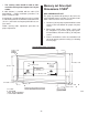
Steering Helm and Cable
STEERING HELM
The steering helm must limit steering cable travel to
88.9 ± 2.5 mm (3-1/2 in. ± 1/8).
!
WARNING
Failure to limit steering cable travel at the helm,
could pre-load the cable resulting in premature
failure of a steering component, causing loss of
steering. This loss of steering could cause prop-
erty damage, personal injury or death.
STEERING CABLE
The steering cable to be used MUST MEET the fol-
lowing criteria:
• 60 Series Steering Cable
• 60 Series bulkhead fitting at output end
• Allow for a minimum of 95.3 mm (3-3/4in.) of
travel.
• Cable end at pump must allow for a 5/16 in.
threaded adaptor shouldered thru-bolt and
locknut to connect the cable to the steering
arm.
• A means of attaching and locking the cable to
the steering cable bracket (provided).
• Protected against water intrusion and/or cor-
rosion as the cable end (at the pump) is sub-
mersed in water with the boat at rest.