
User manual

User Manual : Creating and Configuring Mixers
User Manual
69
Creating and Configuring Mixers
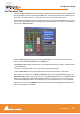
If one of the numerous mixer presets does not quite suit your application it is simple to modify an exist-
ing mixer, create one using the Mixer Wizard or design one from scratch. The Wizard can be started
from an existing mixer by right-clicking anywhere on the mixer surface and selecting Mixer > Settings >
Wizard... Please see also: Mixer Wizard on page 41
I/O Busses Explained
The total number of available output busses, regardless of the number of Mykerinos cards, is 64. The
maximum number of inputs to Pyramix is also 64. However, it is perfectly possible, and permissible, to
have more than 64 physical inputs and outputs connected to a Pyramix system. The PS3 Control
Panel Application acts as a router to assign physical inputs and outputs to Pyramix logical inputs and
outputs. For example: a system containing two Mykerinos boards, one with a MADI daughterboard, one
with an AES/EBU daughterboard has a total of 56 inputs and outputs on the MADI board (64 if MADI X
is used) plus 24 channels of AES/EBU. Possible total 88. Any 64 of these may be routed to Pyramix
inputs and any 64 Pyramix outputs (less the number of assigned Internal Return Busses; see below),
can be routed to physical outputs.
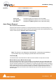
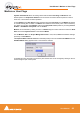
Internal Return Busses
Some of the time slots on the HDTDM bus can be reserved to convey Aux or Master Output Busses
back to input strips. In effect, these are internal send/return paths. To change the number of available
Internal Return Busses, close Pyramix (if open) and launch the VS3 Control Panel Application. The
number of Internal Return Busses can be set using the drop-down list box on the right of the screen.
Click on the OK button to memorize the setting and exit.
The number of Internal Return Busses you assign here will be available as possible channel strip
sources in the mixer.
Mixer Delay Compensation
All digital processing takes a finite amount of time. When Internal Return Busses are used to route
Aux or Master output busses back into channel inputs (by selecting an Internal Return Bus input
from the routing pop-up for the Aux or Bus output, and selecting an Internal Return Bus output as the
return channel input) all other busses not so routed must be delayed if the Mixer is to be ‘time-aligned’
I.e. If a signal is fed to two inputs, the first feeding the Main Output direct and the second routed back to
an input via (say) an Aux bus with the return input strip routed to the Main Output, then the second will
be delayed with respect to the first. Selecting Settings > Enable Delay Compensation from the mixer
context pop-up menu will automatically ensure both signals remain in sync by delaying the signals
directly routed to the Main Output by an amount equivalent to the delay introduced in the second path.
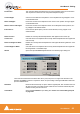
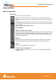
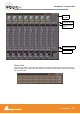
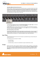
Input Strip Mode
In order for Pyramix to calculate the required delay you have to tell it which bus is the source for the
Internal Return Bus. Clicking on Input at the bottom of the strip, above the XLR icon, pops-up a list of all
the output busses and Input. Input is the default and means the strip is fed from a physical input and no
delay compensation is required. If any bus is ticked and Automatic Delay Compensation is turned on,
Pyramix calculates the required delay and applies it to all Output busses not feeding an internal return
bus.
Delay vs Delay Compensation
When the Input Strip Mode is set to Input the delay setting affects the only the delay on the strip’s sig-
nal. When {any Bus name} Return is selected as the Input Strip Mode the delay setting affects the
delay on all other signals for alignment.