501:440-13 User’s Manual Laminar Flow Elements 10920 Madison Avenue Cleveland, Ohio 44102▪Tel: 216.281.1100▪email:meriam@meriam.com▪Web:www.meriam.
TABLE OF CONTENTS Subject Page Introduction ................................................................................................................................................................ 3 Inspection ................................................................................................................................................................... 3 Installation .................................................................................................................
Introduction Because of their inherently high accuracy, stable calibration, excellent response time and repeatability, Laminar Flow Elements (LFEs) excel in critical gas and air flow measurements and are frequently utilized in validating calibration standards. Standard models are available to measure as little as 0.2 SCCM (5.9 E-06 SCFM) to as much as 2250 SCFM at standard conditions. Custom models for up to 15,000 SCFM of air are available.
Operation Establish flow through the LFE. Measure t h e differential pressure between high pressure sensing port and low pressure sensing port. Measure the inlet gas temperature. For standard or mass flow rates, measure absolute line pressure. Refer to calibration curve/table instructions for flow rate calculations.
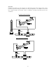
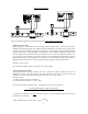
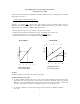
Laminar Flow Systems or MDT 500 Figure1: Typical Installations of Laminar Flow Elements Actual, Standard, or Mass Flow Calibration Curve Table Meriam performs an air calibration of the LFE using a master flowmeter that is traceable to the National Standards and Technology (NIST). The calibration data is standardized to an equivalent dry gas flow rate at 70ºF (21.1ºC) and 29.92 inches Hg absolute (101.3 kPa abs.). (The customer may request another standard condition such as OºC.
To help calculate the viscosity of air at flowing temperature, a viscosity equation based on temperature is included in this instruction manual (see Table A-32422). The equation is from “tables of Thermodynamic and transport Properties of Air, Argon, Carbon Dioxide, Oxygen, and Steam.
Be sure to use the same absolute units for pressure (i.e. PSIA, mm Hg absolute,...) and temperature (ºK or ºR). The result is the standard volumetric flow rate at the given standard conditions. Standard volumetric flow rate = Actual volumetric flow rate x ( )2,- ( This equation can be rewritten: (B x DP + C x DP²) x A2,- A2,- 0x( )5 D5 0 x (D2,-0 A5 A5 D5 0 x (D2,-0 Table A-31031 lists the values of Pf/Pstd absolute line pressures from 26”Hg at 0.05” Hg intervals. The standard pressure is 29.
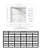
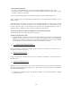
Temperature oF Air Viscosity Correction Factor for Humidity, Uwet/Udry 50 60 70 80 90 100 110 120 130 140 150 1 10% Humidity 20% Humidity 0.99 30% Humidity 40% Humidity 0.98 50% Humidity 60% Humidity 70% Humidity 0.97 80% Humidity 90% Humidity 0.96 Figure2: Relative humidity correction factor for air viscosity. A-35500 Kestin & Whitelaw Table A-35600 (NBSIR 83-2652) Humidity Correction Factor for Air = Pwet / Pdry % Relative Humidity °F 20% 40% 60% 80% 100% 40 .9993 .9987 .9981 .
Determining Flow from your Laminar Flow Element Calibration Curve/Table The curve/table of each LFE is normalized to standard conditions listed by multiplying the calibration data points by the ratio of: J32K423,/ 45 C<2 <, K
Actual Volumetric Flow Rate 1) To obtain actual volumetric flow rate at inlet flowing temperature other than 70ºF, find the flow rate (Q) that corresponds to the corrected DP. Multiply Q by the viscosity correction only. See chart A-31986 for corrections. 2) At flowing inlet temperature of 70ºF read curve directly in actual volumetric flow rate. Actual volumetric flow rate equals standard volumetric flow rate when flowing conditions are 70ºF and 29.92" Hg.
Actual Volumetric Flow Rate 1) To obtain actual volumetric flow rate if the inlet temperature is different from standard temperature, read the flow rate (Q) from the curve corresponding to the corrected DP. Calculate the viscosity at the flowing temperature using the viscosity equation for the flowing gas. Then calculate the viscosity correction factor using µcf = J32K423,/ K412,<1, 5.4: K=.J+/,
Table A-31031 Meriam Laminar Flow Element Pressure Correction Factor (any Gas) Base Pressure (Assigned Standard) 29.92 Inches Mercury Absolute LAMINAR INLET LAMINAR INLET PRESSURE INCH PRESSURE INCH HG. ABS Pcf. HG. ABS. Pcf. 26.00 26.05 26.10 26.15 26.20 26.25 26.30 26.35 26.40 26.45 26.50 26.55 26.60 26.65 26.70 26.75 26.80 26.85 26.90 26.95 2700 27.05 27.10 2715 27.20 27.25 27.30 27.35 27.40 27.45 27.50 27.55 27.60 27.65 27.70 27.75 27.80 27.85 27.90 27.95 28.00 .8689 .8706 .8723 .8739 .8756 .8773 .
Table A-31986 Air Viscosity Correction Factors for ACFM Base Viscosity 181.87 Micropoise at 70°F Correction Factor = TUT.V )W∗ Note: These correction factors do not correct for volume changes due to temperature Temp °F +0 +1 +2 +3 +4 +5 +6 +7 +8 +9 50 1.03034 1.02877 1.02720 1.02564 1.02408 1.02253 1.02099 1.01945 1.01792 1.01639 60 1.01487 1.01336 1.01185 1.01035 1.00885 1.00736 1.00588 1.00440 1.00292 1.00146 70 1.0000 0.99854 0.99709 0.99564 0.99420 0.99277 0.
Table A-32422 Air Temperature/Viscosity Correction Factors for SCFM Air Base T e m p e r a t u r e 7 0 °F 181.7 Micropoise Reference NBS Circular 564 Correction Factor = YZ[.\V ]Y[.\V^ °_ x TUT.V )W∗ µair = 14.58 x 110.4 + ( ( ]Y[.\V^ °` a T.U ]Y[.\V^ °` T.U 0 0 Z Temp °F +0 +1 +2 +3 +4 +5 +6 +7 +8 +9 50 1.0707 1.0670 1.0633 1.0596 1.0559 1.0523 1.0487 1.0451 1.0415 1.0379 60 1.0344 1.0308 1.0273 1.0238 1.0204 1.0169 1.0135 1.0101 1.0067 1.0033 70 1.0000 .
Temp °F +0 +1 +2 +3 +4 +5 +6 +7 +8 +9 50 1.0392 1.0372 1.0352 1.0332 1.0311 1.0291 1.0271 1.0252 1.0232 1.0212 60 1.0192 1.0173 1.0153 1.0134 1.0115 1.0095 1.0076 1.0057 1.0038 1.0019 70 1.0000 0.9981 0.9962 0.9944 0.9925 0.9906 0.9888 0.987 0.9851 0.9833 80 0.9815 0.9797 0.9778 0.976 0.9742 0.9725 0.9707 0.9689 0.9671 0.9654 90 0.9636 0.9619 0.9601 0.9584 0.9567 0.9549 0.9532 0.9515 0.9498 0.9481 100 0.9464 0.9447 0.943 0.9414 0.
When you decide to have your LFE cleaned, please be aware of the various capabilities of calibrating LFE’s at Meriam. Every calibration includes: 6-8 calibration points [differential pressure 1”-8”H2O], a data sheet with raw and reduced data, calibration curve, and instruction manual. The procedure numbers are noted in (parentheses).
LFE Dimensions 17