User’s Manual 9R000045-F January, 2011 M2 – Series Smart Manometer USER’S MANUAL Meriam Process Technologies’ M2 Series Products (M200 Smart Manometer, M200-DI Wet / Wet Smart Manometer, M200LS Lab Standard Smart Manometer and M201 Rotary Gas Meter Tester) are microcontroller based devices used to directly measure and display pressure. Differential (dry/dry), Differential (wet/wet), Gauge, Compound and Absolute type pressure sensors are supported.
Safety Information Failure to follow all instructions could result in injury. Read, understand and follow all safety warnings and instructions provided with this product. Also, meet or exceed your employer’s safety practices. In no event shall Meriam be liable for any indirect, special, incidental, consequential or punitive damages or for any lost profits arising out of or relating to any services provided by Meriam or its affiliates.
For customer assistance please call your local Meriam representative or Meriam directly. Meriam Process Technologies 10920 Madison Avenue Cleveland, Ohio 44102 Telephone: (216) 281-1100 Fax: (216) 281-0228 E-mail: meriam@meriam.com Web: www.meriam.
Table of Contents Certification/Safety/Warnings ................................................... 1 User Interface ............................................................................... 4 1. Keypad Functions .............................................................. 4 On/Off & (backspace) Key ........................................... 4 Min/Max & (up) Key ..................................................... 4 Hold & (down) Key........................................................
Specifications ............................................................................. 23 EC Declaration of Conformity .................................................. 26 Changing the Batteries ............................................................. 27 User Connections ...................................................................... 29 Service and Calibration ............................................................. 31 Appendix 1: Rotary Gas Meter Tester Instructions ................
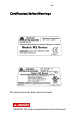
User’s Manual 9R000045-F January, 2011 Certification/Safety/Warnings All M2 Series models are available for general purpose use (nonhazardous areas). Optional Intrinsically Safe (I.S.) certification for hazardous area use is available for all models except the M200LS. General Purpose (G.P.) versions are identified by the name plate located on the rear of the unit under the protective rubber boot.
use the unit in accordance with this document will void the certification and may cause potentially dangerous conditions. For Intrinsically Safe M2 Series Restrictions apply to the use of Intrinsically Safe models in hazardous areas. Refer to the Intrinsic Safety Control Drawing No. 9R000056 for more information. Substitution of components will void the Intrinsically Safe Certification and may impair operation and safety. Do not substitute components.
For General Purpose M2 Series Substitution of components may impair operation and safety. Disconnect power before servicing. The product should not be powered with a combination of new and old batteries. The product should not be powered with a combination of batteries from different manufacturers. For All Models Do not exceed the Pressure Limits listed in the Specifications section of this manual. Failure to operate within the specified pressure limit could result in minor or moderate injury.
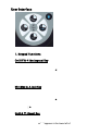
User Interface 1. Keypad Functions On/Off & (backspace) Key Turns the manometer on and enters the unit into the Measure Mode. Pressing the key while in the Measure Mode turns the unit off. It also serves as a backspace key when editing in the Program Mode. The key takes the user out of a programmable register without changing the previous setting. Pressing this key repeatedly will return the user to the Measure Mode and then shut off the manometer.
the display. The key is used to scroll through programmable registers with the unit in the Program Mode. Once a programmable register is selected the key can be used to edit that register. Prgm & (enter) KEY Puts the manometer into the Program Mode from the Measure Mode. When in the Program Mode, pressing this key selects the programmable register to be edited (with prompt for password if Lockout is set).
To Zero AI (Absolute) Type Manometers Start with the unit turned OFF and use the following keystroke sequence: Keystroke 1. Press ON/OF button. Display The display briefly shows header name and full scale range in the last engineering unit selected. Then goes into the Measure Mode to display pressure 2. Connect the M200 to a vacuum source capable of a vacuum of 100 microns absolute pressure or less. 3. Pull a full vacuum. Display should read close to zero. (See note on next page) 4.
Units Select The standard engineering units available on the Smart Manometer are: PSI inH20 (@20°C, 60°F and 4°C) Kg/cm2 kPa mbars Bars cmH2O (@ 20°C) inHg (@ 0°C) mmHg (@ 0°C) User Units Flow Units To change the engineering units the manometer should be “ON” and in Measure Mode. Then follow these steps: Keystroke 1. Press the PRGM key. 2. Press the PRGM key. 3. Press the up or down arrow key until desired engineering unit is displayed. 4. Press the PRGM key to select the engineering unit. 5.
User Unit Select Engineering units not included in the standard selection can be programmed into the manometer using the Units Select register in the program mode. The value programmed into this register is used to calculate the desired unit of measure. An example of converting to “Feet of H2O” will be shown in the following steps, using the conversation factor of 1 PSI = 2.30894 FT H2O. Keystroke 1. Press the PRGM key. 2. Press the PRGM key. 3.
down arrow keys to display the correct value. 10. Press the PRGM key until the display changes. See note 1 at bottom of this table. 11. Press the PRGM key. 12. Follow steps 6-8 above to enter “FT H2O”. 13. Press the PRGM key. 14. Press the down arrow key. 15. Press the PRGM key. Top line reads “VALUE=”. Bottom line reads “CHANGE?: YES”. Top line reads “USER UNIT NAME”. Bottom line reads “FT H2O”. Last letter “O” is blinking. Top line reads “PROGRAM MODE”. Bottom line reads “UNITS SELECT”.
calculation sheet), any flow unit DP = Differential pressure corresponding to Q, unit must be inches H20 @20°C Example: If the DP is 25 inches H20 @20°C when the flow rate is 10,000 units, then the Flow constant is 2,000. Damp Rate Select Adjustable exponential type damping is available to steady the display when measuring pulsating pressure or flow. The Smart Manometer has a range of damping rates; 0.1, 0.2, 0.5, 1, 2, 5, 10, or 25 seconds.
User Info Select (Accuracy, SW version, Mfr date, SN) The User Info Select registers are designed to provide the user with information about the manometer’s hardware and software. This register provides read only information on the sensor’s accuracy, software version, date of manufacture and serial number. It also allows the user to edit the Auto Shut-Off, Lockout and Start-Up Header Name features. To configure the User Info Select registers, follow the steps below. Keystroke 1.
Auto Shut-Off Enabling the Auto Shut-Off feature allows the manometer to turn itself off after a user selected period of keypad inactivity. Selectable options include DISABLED, 10 Minutes (which is the factory shipped default), 20 Minutes, 30 Minutes, 45 Minutes and 60 Minutes. Disabling this feature requires the manometer to being turned off manually using the On/Off key. To configure auto shut-off follow these steps: Keystroke 1. Follow steps 1-6 in the User Info Select table. 2.
Lockout Select Enabling the Lockout feature prevents unauthorized users from making changes to the configuration of the manometer. To enter the Program Mode when Lockout is active, the user must first enter the “password” (two-digit Lockout Code) within approximately 40 seconds of the display prompt. Failure to enter the correct two digit code within approximately 40 seconds will return the unit to Measure Mode. Any two-digit numeric code can be programmed.
Header Name Follow the steps below to edit the Header Name. Keystroke Display 1. From the Measure Top line reads “PROGRAM Mode press the PRGM MODE” and bottom line key. reads “UNITS SELECT”. 2. Press the up arrow Bottom line changes to key twice. “USER INFO SELECT”. 3. Press the PRGM key. Bottom line shows serial number. 4. Press the up arrow Top line reads “HEADER key six times. NAME” and bottom line reads “MERIAM”. The cursor flashes at bottom left. 5.
Contrast Select The Contrast Select register allows the user to adjust the character contrast of the LCD display to provide the best visibility for the ambient light conditions. To adjust the contrast, follow these steps: Keystroke 1. From the Measure Mode press the PRGM key. 2. Press the up arrow key three times. 3. Press the PRGM key. 4. Press the up or down arrow keys to increase or decrease the contrast value. A low number gives maximum contrast and a high number gives minimum contrast. 5.
Data Logging Data Logging can be used to record pressure measurements. Two record modes are supported; automatic and manual. In automatic mode, a pressure value is captured every 5 seconds for 20 minutes, resulting in 240 stored values. In manual mode, a pressure value is captured each time the PRGM key is pressed up to 240 values. The data collected during a logging session can be viewed upon completion. Keystroke 1. From the Measure Mode press the PRGM key. 2. Press the up arrow key four times. 3.
Leak Test The Leak Test feature allows the user to determine the leak rate in the pneumatic system being monitored. Once configured, Leak Test monitors the measured pressure over time and displays the leak rate in “pressure units per minute” at the conclusion of the test. The maximum configurable leak test period is 1440 min (1 day). Pressing any key during the leak test will abort the test. To enable Leak Test follow these steps: Keystroke 1. From the Measure Mode press the PRGM key. 2.
Re-Calibration The Manometer can be re-calibrated in the field for zero, span, and linearity. The proper primary standards must be available prior to calibrating the Manometer. These standards should meet the accuracy requirements for your company or industry. Meriam Process Technologies follows the guidelines established by ANSI / NCSL Z540-1-1994 which requires that the primary standard be 4 times more accurate than the unit under test.
Re-Calibration – 1 Point EDIT and START To perform a 1-point re-calibration, apply a pressure between 50% and 100% of Full Scale and then follow these steps: Keystroke 1. With unit OFF, press and hold the MIN/MAX key, turn the unit on by pressing the ON/OFF key, then release MIN/MAX. 2. Press the up arrow key until “START” is displayed on the bottom line. 3. Press the PRGM key. 4. Press the PRGM key. 5. Press the up/down arrow keys to edit the selected digit.
Re-Calibration – 5 Point EDIT To edit the calibration points for a 5 Point re-calibration follow the steps below. NOTE: If the factory default values are acceptable, skip this section and proceed to the re-calibration 5-Point START procedure. Keystroke 1. With unit OFF, press and hold the MIN/MAX key, turn the unit on using the ON/OFF key, then release 2. Press the PRGM key. 3. Press the up/down arrow keys to edit the selected digit. Use the left/right arrow keys to change the cursor position.
Re-Calibration – 5 Point START To begin the 5-point re-calibration procedure, turn the unit OFF and follow the steps below. Keystroke 1. Press and hold the MIN/MAX key and turn the unit on by pressing the ON/OFF key. 2. Press the up arrow key until “START” is displayed on the bottom line. 3. Press the PRGM key. 4. Press the up arrow key until “5-POINT” is displayed on the bottom line. 5. Press the PRGM key. 6.
10. Use up or down arrow keys to select NO or YES when asked “Save?” the ReCalibration data. 11. Press the PRGM key at YES to save the Re-Calibration data or at NO to exit without saving. 12. Press the left arrow key. Top line reads “SAVE?”. Bottom line reads “NO” or “YES”. Top line reads “RE-CAL”. Bottom line reads “START”. Re-cal is complete. Returns to Measure Mode. Re-Calibration – Restore Factory Defaults To restore the re-calibration data to the factory defaults, follow these steps: Keystroke 1.
Specifications Type, Range and Display Resolution Differential Non-Isolated Types (M200, M200LS, M201): 10 inH2O (0.35 psid) – XX.YYY (M200 only) 28 inH2O (1 psid) – XX.YYY 200 inH2O (7.21 psid) – XXX.YY 415 inH2O (15.0 psid) – XXX.YY (M200 only) 2000 inH2O (72.1 psid) – XXXX.Y (M200 & M200LS only) Gauge Isolated Types (M200 & M200LS) 15 psig – XX.YYY (M200 only) 30 psig – XX.YYY 50 psig – XX.YYY 100 psig – XXX.YY 300 psig – XXX.YY (M200 only) 500 psig – XXX.YY 1000 psig – XXXX.
Accuracy: M200, M200-DI, M201 0.05% of Full Scale or optional 0.025% of Full Scale (0.05% F.S. only for M200-DN0010 [10” H2O range]) Accuracy: M200LS 0.01% of Full Scale (0.02% F.S. for M200LS-DN0028 [28” H2O range]) Accuracy statements include the combined affects of linearity, repeatability, hysteresis and temperature over the specified operating temperature range. Warm up time = 5 minutes. Unit should be zeroed at working ambient temperature before use.
Connection 1/8” female NPT, 316L SS. DN and DI Types: P1 is the high pressure connection, P2 is the low pressure connection. GI, CI & AI Types: P1 is the pressure connection and P2 is plugged with factory fitting. Standard DN & DI manifold GI, CI & AI manifold Battery Type 4 each AA alkaline batteries. ATEX certified models require the use of approved batteries to maintain the ATEX certification. Refer to Dwg. No.
EC Declaration of Conformity This is to declare, in accordance with Directive 94/9/EC, that the following product(s) are designed and manufactured in accordance with Annex II of Directive 94/9/EC. The manufacturer attests on their own responsibility that the apparatus has been constructed in accordance with the principles of good engineering in safety matters, and that any routine verification and test required by Clause 27 of EN 60079-0:2006 has been successfully completed.
Changing the Batteries ATEX certified models require the use of approved batteries to maintain the ATEX certification. Refer to Dwg. No. 9R000056 “M2 Intrinsically Safe Control Document” for a list of batteries approved for hazardous atmospheres. A copy of this drawing accompanies each unit shipped. Remove and / or replace batteries in nonhazardous areas only. Also see the Certification/Safety/Warnings section of this manual for additional important information. The manometer is powered by four, 1.
To install the four batteries: 1) Make sure polarity of battery matches the markings in the compartment. 2) 1st place the (+) end of the battery into the battery slot. 3) Then push in the (-) end of the battery until seated in the bottom of the battery slot. The battery compartment has stand offs molded into the side of the compartment.
User Connections Connection: 1/8” female NPT, 316L SS. P1 is the high pressure connection. P2 is the low pressure connection. The pressure connections are marked in two locations, identified as P1 and P2. One location is the top of the keypad (shown on cover photo). The second marking is stamped into the pressure manifold, next to the pressure connections, as shown below.
GI, CI and AI models use only the P1 pressure port. The unused P2 port vents the enclosure to atmosphere (a vent plug is factory installed in the P2 port). Connection to the incorrect pressure port on DN or DI differential pressure modules may cause damage to the pressure sensor. See the Specifications section of this manual for over pressure limits. If over pressure damage occurs, the unit must be returned to the factory for sensor replacement.
Service and Calibration If the M2 cannot be zeroed, recalibrated or is damaged, it must be returned to the factory for servicing. In this case, contact the Meriam Process Technologies representative in your area or call the factory at the numbers listed below for a Return Material Authorization (RMA) number. DO NOT send any unit in for service without first contacting Meriam for a Return Material Authorization (RMA) number.
Appendix 1: Rotary Gas Meter Tester Instructions The M201 Rotary Gas Meter Test has unique firmware designed for natural gas distribution companies performing drop tests across positive displacement (rotary vane) meters in the field. This model uses the same pressure sensor technology and packaging as other M2 Series products but uses custom firmware to provide a mathematically averaged pressure from test start to test stop. The user determines the test duration.
Appendix 2: M200-DI Application Notes Zeroing for Position Sensitivity M200-DI (wet/wet) units have liquid filled, sealed sensor assemblies. The fill fluid will apply hydrostatic head pressure to the DP sensor in uniform ways depending on the orientation of the handheld during measurement sessions. Horizontal plane (yaw axis): No zero offset Vertical plane (pitch axis): No zero offset Roll axis: Zero offset occurs.
Appendix 3: M200LS Lab Standard Smart Manometer The M200LS models provide greater accuracy than the standard M200 for users in controlled or temperate climates. Typical accuracy is ± 0.01% FS over the temperature range of 59º F to 86º F (15º C to 30º C). Accuracy is not certified outside this reduced temperature range. The display for all M200LS pressure ranges is 6 digits for PSI units of measure. 6 digit display of pressure in other engineering units is supported whenever possible.