
Instruction Manual


INSTALLATION AND PRECAUTIONS
Read these instructions before installing the gauge. The configuration options may be
easier to set up before the gauge is installed.
NEVER insert objects into the gauge port or blow out with compressed air. Permanent
damage will result to the sensor.
Use an appropriate screen or filter to keep debris out of gauge port.
Use fittings appropriate for the pressure range of the gauge.
Due to the hardness of 316L stainless steel, it is recommended that a thread sealant be
used to ensure leak-free operation.
Install or remove gauge using wrench on hex fitting only. Do not attempt to tighten by
turning housing or any other part of the gauge.
Do not apply vacuum to gauges not designed for vacuum operation. Permanent damage
will result to the sensor.
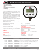
POWER-UP
1. Press the front button.
2. The full-scale range is indicated and the display segments are tested.
3. The actual pressure and units are displayed.
POWER-UP WITH ZERO
1. Be sure the gauge port is exposed to normal atmospheric pressure and no pressure or
vacuum is applied. The zeroing function is only activated at each power-up and the
stored zero correction is erased when the gauge is shut off.
2. Press and hold the front button until
oooo
is displayed and then release the button.
This indicates that the gauge has been zeroed.
3. The full-scale range is indicated and the display segments are tested.
4. The actual pressure and units are displayed.
Attempting to zero the gauge with pressure greater than approximately 3% of full-scale
applied will result in an error condition, and the display will alternately indicate E r r0
and the actual pressure. The gauge must be powered down to reset the error condition.
NORMAL OPERATION
Following the start-up initialization, the display indicates the pressure reading updated
approximately 3 times per second. The auto shutoff timer starts when the gauge is pow-
ered up or whenever the button is pushed, unless the gauge is set up with the auto shutoff
timer turned off (0 AST).
If excessive vacuum is applied to a pressure-only gauge, the display will indicate
– E r r until the vacuum is released. Applying vacuum to a gauge designed for pressure
may damage the pressure sensor. If excessive pressure is applied (112.5% over range), an
out-of-range indication of i – – – or i –.–.–.– will be displayed depending on model.
MINIMUM AND MAXIMUM READINGS
Minimum and maximum readings are continuously stored and updated whenever gauge
is on. The stored readings can be manually cleared if desired. The high and low memory
is also cleared whenever the gauge is off.
Press and hold the button for about 1 second until HI is displayed alternating with the
units. The maximum stored value is displayed.
After HI is displayed, press and hold the button again for about 1 second until LO is
displayed alternating with the units. The minimum stored value is displayed.
After LO is displayed, press and hold the button again for about 1 second until AP
(Applied Pressure) is displayed. The high and low readings are kept in memory and the
gauge returns to normal operation with the display indicating the current pressure.
Press and continue to hold the button until the display indicates
C
ir Hi/Lo (about 3
seconds total) and then release the button. Both HI and LO values are cleared and the
gauge returns to the normal mode and displays the current pressure.
SHUT-DOWN
To shut off the gauge manually at any time, press and hold the button until the display
indicates OFF (about 5 seconds) and then release.
When an auto shutoff time is set, the display indicates OFF five seconds prior to auto
shutoff. The button can be pressed to keep the gauge on. The auto shutoff timer is reset
whenever the button is pressed and released.
If the gauge is set up with the auto shutoff timer turned off (0 AST) it will stay on until
manually shut off or until the batteries are depleted. Turn gauge off when not in use to
conserve battery life.
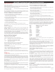
DIMENSIONS
OPERATION SUMMARY
ENGINEERING UNIT SELECTION
Engineering unit selection is done via internal buttons to help prevent accidental or
unauthorized changes in the field. The selected engineering unit is stored in non-volatile
memory and will be retained even with the battery off or batteries removed. The avail-
able engineering units depend on the sensor range, display resolution, and is limited to
prevent unwanted reading instability.
Compound (inHg/PSIG) gauges can be changed to display single-unit vacuum/pressure
readings (i.e. ±psig) when in the user configuration mode.
Standard PSIG units are mathematically converted to the newly selected engineering
unit. When the gauge is powered up, the originally configured PSIG range is displayed
and then the conversion with the selected engineering unit is displayed.
To change engineering units and remove the rear cover to gain access to the two internal
buttons located near the lower right and left corners of the circuit board.
With the gauge powered up, press and hold the UP button. Release the button when the
engineering units begin to flash.
Use the UP and DOWN buttons to scroll through the list of engineering units available
for the pressure range of the sensor.
When the desired units are displayed, press and release the front button to save the selec-
tion and return to normal operation.
Replace the rear cover taking care not to pinch the power wires between the cover and
the case.
AUTO SHUTOFF TIME SELECTION
Auto shutoff time selection is done via internal buttons to help prevent accidental or
unauthorized changes in the field. The selected shut off time is stored in non-volatile
memory and will be retained even with the battery off or batteries removed.
Remove the rear cover to gain access to the two internal buttons located near the lower
right and left corners of the circuit board.
With the gauge powered up, press and hold the DOWN button. Release the button when
the auto shutoff time is displayed on the upper section.
The lower display segments will indicate AST M if the time displayed is in minutes,
and AST H if it in hours.
An auto shutoff time of zero signifies that the auto shutoff feature is disabled.
Use the UP and DOWN buttons to select 0, or 1, 2, 5, 10, 15, 20 or 30 minutes, or 1,
2, 4, or 8 hours.
When the desired auto shutoff time is displayed, press and release the front button to save
the selection and return to normal operation.
Replace the rear cover taking care not to pinch the power wires between the cover and
the case.
BATTERY REPLACEMENT
A low battery indication will be shown in the upper left-hand corner of the display when
the battery voltage falls sufficiently. The battery should be replaced soon after the indica-
tor comes on or unreliable readings may result or the gauge may fail to power up.
1. Remove the 6 Phillips-head screws on the back of the unit.
2. Remove batteries by lifting up the positive end of the battery (opposite the spring)
taking care not to bend the battery holder spring.
3. Always replace both batteries at the same time with high quality alkaline batteries.
Install batteries with correct orientation. The negative (flat) end of each battery should
be inserted first facing the battery holder spring.
4. Replace the back cover, including the rubber sealing gasket taking care not to pinch
the power wires between the cover and the body of the case.
MGF16BN Instructions
© 01-09Specifications are subject to change without notice.
Function Button Prompt—Release Button Result
Gauge On Press Gauge Range/Display Test Actual Pressure
Gauge On & Zero Press/hold
oooo
Zeroed Actual Pressure
Hi Reading Press/hold HI Maximum Reading
Lo Reading Press/hold Lo Minimum Reading
Exit Hi/Lo Press/hold AP Actual Pressure
Clear Hi/Lo Press/hold HI / LO / AP +
C
i
r
Actual Pressure
Off, Clear Zero Press/hold HI / LO / AP +
C
i
r
+ OFF Gauge Off, Clear Zero
10920 Madison Ave
Cleveland, OH 44102
Phone: 216-281-1100
Fax: 216-281-0228
¼" NPT
3.5"
0.75"
2.0"
XXXXX
8
8888
2
3.0"
i i i i i
t
s