MERIDIAN DSP5000 USER MANUAL Meridian Audio Ltd 14 Clifton Road Huntingdon Cambridgeshire PE18 7EJ England Tel (0) 480 52144 Telex 32577 (MERIDN) Fax (0) 480 459934 Meridian America Inc.
Contents Introduction ............................................5 About this manual ..................................5 DSP5000 description ..............................6 Master and slave speakers ..................6 Centre, left, right and surround ............6 Control.................................................7 General background ............................7 Unpacking the DSP5000.........................7 Meridian System Remote (MSR).............................................
Guarantee .............................................54 Appendix 1 DSP5000 types .................55 Type 1 setup, Meridian 500 series system using 562 ...............55 Type 2 setup, Meridian CD as preamp (via 607), 204 connected.....................................56 Type 3 setup, 601, 201, 603 or 562 as preamp via 607, Meridian CD and 204 connected.....................................56 Type 4 setup, 601 preamp or 201 or 603 as preamp via 607, Meridian CD and 204, CD with direct connection .........
This page intentionally blank.
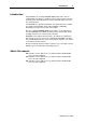
Introduction 5 Introduction Congratulations on choosing DSP5000 digital loudspeakers. We are confident that they will give a quality to your music that is unprecedented, and bring years of listening pleasure. This manual will enable you to get the most from them. The DSP5000 is a sophisticated product. You should therefore read all the supplied documentation before fully installing the DSP5000, particularly if you intend to customise its functions.
Description 6 DSP5000 description You will find it simpler to understand how the DSP5000 works if you consider it as a combination of the following components: • digital preamplifier, to select and control up to two digital sources directly, and to provide fixed and switched digital output for the other DSP5000 • digital audio processor, whose functions include decoding as well as error detection and correction • digital signal-processor, dealing with tone controls, digital crossover, dynamic bass control
Description 7 Control The DSP5000s are operated either by commands received from the Meridian System Remote (MSR) supplied with the loudspeakers, or by commands received through the communications cables of a Meridian installation (for example, from the front panel of a 562 or 601). The remote control provides enough keys to allow you to drive a Meridian installation via the DSP5000s, and this is the method to be preferred.
Installation 8 • hex wrench (3mm), for drive units If any of these items is missing, please contact your dealer. We suggest that you retain the packing carefully, as it provides maximum protection for the unit in transit. NOTE Take great care when unpacking or re-packing the DSP5000 that you do not put undue pressure on the front, as the drive units may be damaged if pressed. Fitting the feet It is easiest to fit the feet with the speakers upside down, before removing the inner carton or foam packing.
Installation 9 Note Additional MSRs can be obtained from your dealer if you would prefer to have more than one.
Using DSP5000 10 Installing your DSP5000 General precautions Before carrying out any installation, you should ensure that the DSP5000 is marked with the correct voltage for your local AC supply. Should this not be the case, do not proceed, but contact your dealer. As a general rule, you should not make any connections to the DSP5000, or to any other component in your system, when the AC power supply is switched on.
Using DSP5000 11 Calibration and Test are intended only for use by the factory or by service engineers. Connections For details of making all connections, see Connecting DSP5000, on page 42 You will need to make four types of connection to the DSP5000: • digital audio • communications • master–slave • AC power Digital audio connections will need to be made to other components in your system.
Using DSP5000 12 Final adjustments When you are sure that the DSP5000s are in the right places, you should adjust and finally tighten the feet with the wrench provided. We strongly suggest that you try to use the spike feet, in order to get the best sound. • Foot caps may be fitted if the spikes are unacceptable The spikes allow the DSP5000s to rest firmly on the floor. A spike passes through carpet to the wood or concrete below, and does less damage in the long run than a wide foot.
Using DSP5000 13 Starting the DSP5000 To start the system, press any of the input keys on the MSR (CD, LP, Radio, Video, Tape 1, and Tape 2). For example: 1. Press CD In Type 1 this will select the physical input D1, and both DSP5000s will display cd 65 65 is the volume number, and cd means that the DSP5000 expects the source to be a Meridian CD player which can be controlled by the MSR.
Using DSP5000 14 Basic operation of DSP5000 Note DSP5000 is factory set for the most common installation, one using the full features of a Meridian 500-Series CD player and 562 controller. We call this a Type 1 installation. For more details, see Appendix 1 on page 55. Selecting sources To switch from CD to another input, say Radio: 1. Press Radio In Type 1, this will select RD on a Meridian 562.
Using DSP5000 15 Display DSP5000 displays information to help you operate it.
Using DSP5000 16 1 Here 1 is the number of the track currently playing on the disc. If the disc includes significant index points, the display will be like this: 3.4 3.4 here means track 3, index point 4. In theory, with the right disc, we could see displays of track and index up to 99.99. Index point 1 is never displayed.
Using DSP5000 17 Note Subjectively one judges a volume increase of 9dB to be equivalent to a doubling of loudness, so each volume number represents about a 11% change in loudness, with nine steps to double loudness.
Using DSP5000 18 Mute To mute the sound: 1. Press Mute The display now shows that the sound is ‘attenuated’: Att. To demute (restore the sound level): 1. Press Mute The Mute key toggles between mute and demute. The system may also be demuted by selecting another source, or adjusting the volume. The menu system The DSP5000 offers a number of user choices which are normally accessed less frequently than, for example, source and volume.
Using DSP5000 19 perhaps to compensate for a non-central listening position or a highly asymmetric layout. This is certainly not the case. Stereo sound is dependent upon time differences between the signals from the channels. To get the best out of a normal stereo system, you should be in the correct position in relation to the speakers.
Using DSP5000 20 Note This will also reset the bass and tilt controls.
Using DSP5000 21 Tilt control Tilt controls are combination controls that slope the frequency response of the system slowly over the frequency range to make the sound brighter or dimmer. They are less crude than conventional tone controls. The responses of the tilt control in DSP5000 are shown in Appendix 4 on page 61. To review the tilt setting: 1. Press the w or the e menu key until the tilt display shows. The master display will momentarily show t. 0.
Using DSP5000 22 Bass control The bass control allows you to adjust the bass response in the room. The responses of the bass control in DSP5000 are shown in Appendix 4 on page 61. To adjust the bass: 1. Press the w or e menu key until the bass cursor display shows. The master display will momentarily show b. 0.0 This allows you to ask the DSP5000 what its bass setting is without changing it. To change the bass: 1. Make sure that you can see the bass cursor display on the master. 2. Press the n menu key.
Using DSP5000 23 Experiment with the sound of the setting. If you are not sure, set it to positive phase. Axis To adjust the axis: 1. Press the w or e menu key until the axis cursor display shows. The master display will momentarily show A. 0 This allows you to ask the DSP5000 what its axis setting is without changing it. To change the axis: 1. Make sure that you can see the axis cursor display on the master: A. 0 2. Press either the n or s menu key.
Using DSP5000 24 Recalling settings The settings stored in the DSP5000 can be recalled at any time. When the display is normal (i.e. not a tone cursor): 1. Press Store The DSP5000 will respond with rEc. Tip You can now compare the stored settings with the standard ones. Use the Clear key to restore a flat response, then Store to recall the stored settings. Note When you change sources, you will need to press Store to recall any favourite tone setting you may have stored.
Operation 25 Controlling a Meridian CD player Use of handset to control CD You are advised to operate the system with the MSR. Playing a disc On the MSR, the following keys operate the Meridian CD: To start a disc 1. Press Play To stop the disc 1. Press Stop To make the disc pause 1. Press Pause The Pause indication on the Meridian CD will light up. If the DSP5000 master was displaying track or time information, it will display PSE To start it again (‘unpause’) 1. Press Pause To cause a disc to repeat 1.
Operation 26 To select a track by number, press the appropriate number key or keys. For example, to select track 6 1. Press 6 The DSP5000 will respond with the display – 6 To engage this selection, press Play or wait for a short time. To select track 15 1. Press 1 followed by 5 The DSP5000 will show – 15 Again, press Play or wait for a short time. If you select a track that does not exist on the disc, the DSP5000 will show an error message: Err.
Operation C. 27 6 Press Play to action a programmed sequence. Use with 504, 204 or 604 FM tuner When a 204 or 604 is the system tuner, it can be controlled by the MSR but only if the DSP5000s are set up in 200 mode (for example by selecting Type 2. A 504 tuner can operate in both 200 and 500 modes. Select the tuner with Radio. The display will show rd. ## where ## is the volume number.
Operation 28 Operation summary On the remote control KEY FUNCTION Off CD, LP etc.
Customising DSP5000: overview 29 Customising DSP5000: an overview DSP5000 is a very sophisticated device, with a number of options which allow you to set up exactly the system you need. Programming of DSP5000s should take place after you have set up the speakers and sorted out most of the connections. If you first get the speakers working with some kind of digital input (e.g. a CD player), and with some of the programming provided (e.g.
Customising DSP5000: how to 30 How to customise DSP5000 DSP5000 needs no customising to become operational. Once you have your system established, you may wish to review the customising options by reading Customising DSP5000: an overview (page 29). Customising: general procedure DSP5000 has seven operating modes (not to be confused with Types): • Standby • Normal • Type • Config • Setup • Calibrate • Test Standby and Normal are the everyday operating modes.
Customising DSP5000: how to 31 Config: control settings In Config, you can make selections that affect the way in which DSP5000 responds to certain keys. The main choices of this kind are: • left or right • master or slave • Multiroom standby option • sort of preamplifier or source switch box in the installation Config: sources and inputs In Config you can make decisions about sources, e.g.
Customising using Config 32 Customising using Type Type is a mode used specifically to restore the entire memory (except the calibration memory) of DSP5000 to one of three factory-preset configurations. For all three Types, Type resets the following: • phase to positive • axis to –1 • balance to central (L 0) • tilt to 0.0 • bass to 0.0 • boundary to Free • speaker to left master Depending on the Type selected, the other options are set as follows. More information is given in Appendix 1, on page 55.
Customising using Config 33 Choosing centre, left or right If you have Typed the speaker with a 6, then the ‘Cen.y’ option is enabled. This tells the speaker that there is a centre in the system and enables the option to make the DSP5000 into a centre. If you Typed the speaker with a number other than 6 then the ‘Cen.n’ option is selected and you do not get the ‘centre’ choice in this section. To change the speaker from left to right, or vice versa. 1.
Customising using Config 34 Inside Config you can move between them at will. To go to 1. root: press Clear 2. system: press Off 3. source: press a source key – e.g. CD Note In Config, the speaker is silenced. How to use Config 1. Switch off the master DSP5000, using the power switch on the back, and wait for 3 seconds 2. While pressing the 0 key on the remote control, switch the power on again. The display will indicate the root menu that shows the left/right and master/slave settings; for example, r.
Customising using Config 35 The display looks like this: Cd ?? The first letters tell you which options are available to you, as follows: • 500 tells you that this system operates in Meridian 500-Series mode. All controllable Meridian products must be 500 compatible. Also use this if the DSP5000 is the only controllable preamplifier connected (i.e. the source keys on the MSR will only select between the two inputs of the DSP5000). • Pr.
Customising using Config 36 have the DSP5000 ignore the Standby state of the associated preamplifier, looking after its own Standby independently. To select this mode while in the system menu: 1. Press Fn - Record The display should indicate 'preamplifier off' like this: ?? P. Toggle this choice with Fn - Record. Setting the Volume mode 1. Press the menu e key LE. 1 In the 500 Comms system there is provision for two volume controls, main and secondary. 2. Use the and menu keys to choose between: • 1.
Customising using Config 37 These parameters are already set up by the Type chosen as the start Type, but they can be adjusted using the following menus. Source menu 1 options Source menu 1 controls the display that will be seen on the DSP5000 when a key on the MSR is pressed in normal use. Think of its function as adapting the keypad to your needs. There are a large number of available legends. To get into source menu 1 1. Press the source key you want to define, e.g. CD or 1.
Customising using Config 38 You get to source menu 2 by using the menu e key while in source menu 1. The display will be like this: cd d1 The first part of the display tells you which key on the MSR you are setting up. The second part of the display tells you which input on the back panel of the master DSP5000 will be selected when this key is pressed. The choices are: d1 Input D1 selected d2 Input D2 selected Use the n and s menu keys to select the second part of the display.
Customising using Config 39 You get to source menu 4 by using the menu e key while in source menu 1. The display will be like this: cd 1A The first part of the display tells you which key on the MSR you are setting up. The second part of the display tells you the address. Normally you should leave this set to ‘1A’ unless advised otherwise by your dealer or Meridian technical support. Use the n and s menu keys to select the second part of the display.
Customising using Setup 40 In Normal operation, the settings you have made will be retained and cannot be changed without going back to Setup. Boundary controls The frequency balance of a loudspeaker is changed, particularly in the low-frequency regions, according to its proximity to walls or boundaries. The DSP5000 is designed as a floor-standing system, so one boundary – the floor – is nominally fixed. The DSP5000's response is also optimised for a rear air-space of about 30cm behind the cabinet.
Customising using Setup 41 Sub.1 Sub.2 Centre-channel options The following two adjustments will appear on the master if the ‘Cen.y’ option is selected in Config or if the speaker has been set to Type 6. It appears on the master – whether or not it is a centre. A DSP5000C (or DSP5000) which is configured as a centre responds to these menu settings.
Customising using Setup 42 Recalling settings in Setup The Store key operates normally as a recall when there is no tone cursor displayed. 1. Wait for a volume, track or time display on the master 2. Press Store Limitations of storing Tilt and bass settings are stored by each source independently. Phase, axis and boundary settings are stored for all sources, and the last setting stored is that used for all sources.
Connecting DSP5000 43 Connectors The connection sockets on the back panel of the DSP5000, and their uses, are as follows: • Comms Output A DIN connector which is used to send information on to the DSP5000 slave or to a 565 Digital Surround Decoder. NEVER connect an audio DIN lead to this socket. • Comms Input A DIN connector which is used to exchange information with other Meridian components NEVER connect an audio DIN lead to this socket.
Connecting DSP5000 44 • If a power-line filter is to be used, try to use a permanent type, and be sure that it is approved to the standards of your territory and that it retains the grounding WARNING: DSP5000 must be grounded. Connection using M5- and S5-leads Many systems will require only the supplied composite M5- and S5-leads. If these are not appropriate, further information can be found in the section starting on page 46. To get a CD player working with the DSP5000s, proceed as follows: 1.
Connecting DSP5000 45 Digital audio connections Note A digital audio connection will be made into the D1 input if you use the M5- and S5-leads supplied as directed in the section starting on page 46. Digital audio has to be conveyed to both DSP5000s in the installation.
Connecting DSP5000 46 Communications connections Communications connections are only made to other Meridian equipment. In general, you can follow the instructions given for the other equipment, and view DSP5000 as a D600 or D6000 for communication purposes. The following sections describe the major points. If you have a Meridian 500-Series only system For example; 500 or 506 CD, 562 controller, 504 FM tuner 1.
Connecting DSP5000 47 If you are using a Meridian 201 or 603 and a Meridian 200- or 600-Series CD player Unless you have an older M-lead (as opposed to M5 lead) you will need to obtain an SP5 adapter. An M-lead has two DIN plugs at one end and this is the end to connect to the preamplifier. The SP5 adapter allows an M5lead to connect to 200-Series products. 1. Connect the phono plug at the far end of the M5-lead (from the master) to the digital output of the CD player 2.
Connecting DSP5000 48 If you are mixing Meridian 200- or 600-Series with 500-Series components 1. Connect the digital and analogue audio as described in the previous sections. 2. Locate the DIN plug at the source end of the M5-Lead. Connect it to one of the sockets COMMS on the rear of a 500-Series unit. 3. Connect the 500-Series communications together as described earlier and in the 500 User Guide(s). 4.
Specification 49 Specification Digital outputs 32kHz, 44.1kHz or 48kHz. Double PLL locks at 44.
Help 50 Help! Standby point not lit Check the following: 1. There is AC power connected to the socket on the rear of the DSP5000 2. The power switch on the rear panel of the DSP5000 is turned on If the DSP5000 still will not light up, check any fuses in your power supply and the fuse in the DSP5000. If these are all intact, contact your dealer. No sound 1. Check the AC power supply to DSP5000. If the power is on, you should be able to see the Standby display in the window: 2. 3. 4. 5. 6. 7.
Help 51 2. If clicks occur randomly with the source selected but stopped, the problem may be the result of loss of lock due to gross electrical interference. Find out whether there is an appliance elsewhere in the house causing the disturbance (e.g. central heating, a pump or a fan). If there is, suppress it. Meridian CD does not respond 1. Check that all connections between the master speaker and the Meridian CD player have been made correctly 2.
Help 52 obtain an up-to-date EPROM and fit it. Operating code can always be updated. 3. Make sure that the whole system is set up in either 200 mode or in 500 mode. Note All Meridian products must be in the same mode. 200 or 600-Series products can only work in 200 mode and if you intend to incorporate these in a DSP5000 system, the speakers and any 500-Series components must be put into 200-mode (normally Type 2).
Help 53 Note DSP5000 is a digital audio and computing device which has been designed to very high standards of electromagnetic compatibility. FCC WARNING: This equipment generates and can radiate radio frequency energy, and if not installed and used correctly in accordance with our instructions may interfere with radio communications or radio and television reception. It has been type-tested, and complies with the limits set out in Subpart J, Part 15 of FCC rules for a Class B computing device.
Help 54 In the USA and Canada, contact Meridian America Inc. 3800 Camp Creek Parkway Building 2400 Suite 112 Atlanta GA 30331 Tel (404) 344-7111 Fax (404) 346-7111 Guarantee The Meridian DSP5000 is guaranteed against defects in material and workmanship for 12 months from the date of purchase. The guarantee is void if the DSP5000 has been subjected to misuse, accident or negligence, or has been in any way tampered with or modified without the written authorisation of DGW Ltd.
Appendix 55 Appendix 1 DSP5000 types Type 1 setup, Meridian 500 series system using 562 The Meridian 562 allows simple control and routing of analogue and digital sources. All connections from sources are made to 562 which then sends a single digital feed to the DSP5000s. Type 1 sets the DSP5000 as a left master, so you will need to make the other a right slave, or adjust left/right on both speakers.
Appendix 56 Type 2 setup, Meridian CD as preamp (via 607), 204 connected The Meridian compact disc player range includes players with built-in preamplifiers, such as the 207 and the 208. To use the analogue inputs of these units, it is necessary to put a 607 (or similar) A/D converter between the fixed output of the preamp section and the D2 input of the DSP5000. It is possible to control one of the previously mentioned CD preamp combinations and a Meridian FM tuner using Type 1.
Appendix 57 Type 4 setup, 601 preamp or 201 or 603 as preamp via 607, Meridian CD and 204, CD with direct connection In this Type, the CD player is directly connected to D1, and all other sources are mediated through an external control unit or preamplifier. The output of an analogue preamplifier (201 or 603) will have to be converted to a digital signal for DSP5000. A Meridian 607 converter is recommended. The Meridian 601 preamplifier incorporates an analogue–to–digital converter for analogue sources.
Appendix 58 Type 5 setup, Meridian 500 system not using 562 The CD is connected directly to D1, all other sources are routed directly or via an A/D converter to D2. Type 5 sets the DSP5000 as a left master, so you will need to make the other a right slave, or adjust left/right on both speakers.
Appendix 59 2. Switch the power off. You have now set the test master. 3. Switch on the power supply to the slave speaker only while continuously pressing the Previous key on the MSR 1L 65 4. Switch the power off. You have now set the test slave. If you now turn both speakers on, they will come up in Test mode. To get back to normal user mode: 1.
Appendix 60 Controls Test mode Remote key Logo Input on DSP5000 Control? Channel selected CD 1L D1 No Left Radio 1r D1 No Right LP 2L D2 No Left Tape 1 2r D2 No Right Internally generated test signals A number of internally generated test signals are available in Calibrate mode. These include: • one sample width impulse with 2Hz repetition rate • four sample width impulse with 2Hz repetition rate • pink noise To switch from the input to the test signals: 1.
Appendix 61 Appendix 4 6dB 4dB 2dB 0dB -2dB -4dB -6dB 10Hz 100Hz 1kHz 10kHz Tilt control responses, showing the steps between +10 and –10 6dB 4dB 2dB 0dB -2dB -4dB -6dB 10Hz 100Hz 1kHz 10kHz DSP5000 bass control, showing 1dB steps between +5 and –5 DSP5000 User Guide
Appendix q y g 62 p 0dB -5dB -10dB Boundary Sub1 Sub2 -15dB -20dB -25dB -30dB -35dB 10Hz 100Hz 1000Hz 10000Hz Relative response of the ‘boundary’ and subwoofer settings DSP5000 User Guide
Index 63 Index 201,use with, 46 207,use with, 46 208,use with, 46 500- and 200-Series mixed, 48 601 use with, 47 603,use with, 46 Address product, 35 system, 35 Att. display, 18 Autoconfigure, 35 Axis explained, 23 listening, 23 using the control, 23 Balance explained, 18 option in surround, 36 using the control, 18 Bass control explained, 22 using, 22 boun.
Index source in Config, 33 source menus in Config, 36 system in Config, 33 Meridian products,use with other, 46 MSR, 7, 8 Multiroom protocols, 35, 36 Mute and demute, 18 Normal how to get back to, 30 Operating basics, 14 summary, 28 Pause, 25 Phase control, 22 explained, 22 Play, 25 Positioning the loudspeakers, 11 Power switch, 12 Preamplifier differences explained, 35 options at setup, 34 Preset favourite, 14 Programming. see Customising Radio interference, 52 rEc message, 24 Recall.
Notes 65 Notes DSP5000 User Guide
Notes 66 DSP5000 User Guide