Installation/Operation Instructions Fiber Optic RGB & DVI Video Transmission System Part Numbers: RGB-T-0 & RGB-R-0 (Single-channel, RGB / DVI Transmitter & Receiver) Page 1 700 Elmont Rd, Elmont, NY 11003, Tel: 516-285-1000; Fax: 516-285-6300 www.Meridian-tech.com 3/07 Rev 1.
Table of Contents 1.0 Product Description....................................................................................................................3 2.0 Installation ..................................................................................................................................3 2.1 3.0 Fiber connections...................................................................................................................3 Product Signal Format & Specifications...................
1.0 Product Description Meridian’s RGB-T/R product is part of Meridian’s new DigiView product family. This state-of-the-art, high performance video transmission system transmits fully-compliant DVI, RGsB or RGBHV signals over one, multimode fiber. Optional DVI adapter cables allow easy interface to standard video connection interfaces on computers, monitors, switches, etc. The RGB-T/R provides real-time, digitized transmission of DVI, RGB and H&V sync signals.
3.0 Product Signal Format & Specifications The RGB series products transmit and receive the following signals over one multimode fiber: • • • • • • 3.
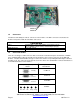
8. If you need to revert back to the original setup conditions, click the “Presets” tab of the ‘RGB Card Interface Transmitter’ and select Current screen size. 9. This concludes the fine tuning adjustments of the RGB-HV transmission system 3.3 RGB to DVI conversion These modems are capable of operating in both RGBHV & DVI modes. Both the Tx & Rx units can be individually configured to transmit/receive either RGBHV or DVI. In order to do this, one switch on the Tx and Rx boards must be set.
Switch #1 Switch #2 3.5 Connectors The tables below identify the various connectors on the modules. The DVI-I connector is mounted to the module’s front panel on both the transmitter and receiver. Connectors Video Standard DVI-I female (with RGBHV analog inputs/outputs) DVI-I to RGBHV (HD-15 female) molded adapter (dongle) 4-pin USB (type B) Multimode - ST RGB adjustment Optical 3.6 Conversion Cables There are several types of DVI connectors that are mounted on standard computers and monitors.
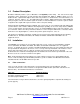
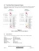
4.0 Front Panel Pinout Assignment Diagram Figure 4.1 below shows the front panel layout, connector location, indicator location and pinout assignment for both the RGB-T and RGB-R modules. This diagram shows the video pinouts for the on-board DVI-I video connector. RGB/DVI-T Pinout Diagram RGB/DVI-R Pinout Diagram Figure 4.1 RGB-T-0 & RGB-R-0 Front Panel Layout Diagrams 4.1 Status Indicators There are function status indicator lights associated these modules.
5.0 Troubleshooting Below is a listing of several problems that may arise during the installation & operation of the modules. If you are having difficulty installing or operating the modules please refer to this list below. Problem: Action: Problem: Action: Problem: Action: Module does not fit in chassis slots Check module orientation.
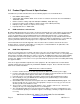
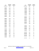
Video Resolution Horizontal Frequency (kHz) Vertical Frequency (Hz) 640x480 640x480 640x480 640x480 640x480 640x480 640x480 640x480 640x480 640x480 640x480 640x480 31.47 35.16 37.86 37.50 43.27 50.90 61.80 72.92 75.00 78.30 90.6 108.0 60 70 72 75 85 100 120 140 144 150 170 200 800x600 800x600 800x600 800x600 800x600 800x600 800x600 800x600 800x600 800x600 800x600 800x600 37.88 43.81 48.08 46.88 53.67 63.60 77.16 90.74 94.10 98.23 112.5 134.
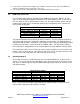
Part Number Variations The table below indicates the part numbers and product description that are included in this manual. Transmitter Receiver RGB-T-0M RGB-T-0R RGB-R-0M RGB-R-0R Description RGBHV & DVI video transmitter/receiver pair, multimode, shelf mount RGBHV & DVI video transmitter/receiver pair, multimode, rack mount Note: Shelf mount (“M”) and rack mount (“R”) units can communicate with each other. Page 10 700 Elmont Rd, Elmont, NY 11003, Tel: 516-285-1000; Fax: 516-285-6300 www.