
User's Manual

34 Researching the requirements
Interface (l/O) cables
-
I/O cables are typically 25conductor flat-ribbon or round cables interfaced
through RS-232-C connectors. These cables are used to connect data units
to printers, host computers, and modems.
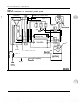
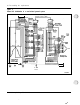
UEM cable routing
Cables may be routed internally in the UEM horizontally in front and at the
rear of the card cage, vertically on the right side only and vertically through
square holes near the rear of the DEM. Cables may be routed externally in
the back of and on the left and right side of the UEM between the EMI/RFI
I/O panel and the rear cover. The cables may be routed in these channels up
to the top of the column or down to the floor through the pedestal.
Note:
Routing cables on the inside of a UEM from the front to the
back on the left or Power Supply side is not recommended. This is
because of the limited access in routing the cables and of the effects of
EMI/RFI noise generated in this area to signals in the cables.
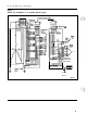
Network to PE cabling
IPE cabling from Network to PE originates from the faceplate of the
Superloop Network card and extends to the backplane connectors on the
Controller card of the
lPE
Module.
---
PE cabling originates from the faceplate of the Network card to the
faceplate of the Dual Loop Buffer.
Power and ground cables
For AC-powered systems, a 9-foot, three-conductor line cord is normally
supplied except in areas where conduit will be required. For DC-powered
systems, wiring is generally done through conduit.
installation planning 553-3001-120
I
c