Home Theater Optimized FDP-DILA2 Installation and Operations Manual NOTICE: THIS PROJECTOR HAS BEEN SIGNIFICANTLY MODIFIED AND OPTIMIZED TO PRODUCE VERY HIGH QUALITY IMAGES USING THE FAROUDJA PROCESSOR. ANY CHANGES MADE TO THESE SETTINGS CAN CORRUPT THIS PROCESS. RESETTING THE OPTIMIZATION IS NOT COVERED UNDER WARRANTY.
SAFETY PRECAUTIONS IMPORTANT INFORMATION IMPORTANT SAFEGUARDS WARNING : TO PREVENT FIRE OR SHOCK HAZARDS, DO NOT EXPOSE THIS APPLIANCE TO RAIN OR MOISTURE. CAUTION : To reduce the risk of electric shock, do not remove cover. Refer servicing to qualified service personnel. Electrical energy can perform many useful functions. This unit has been engineered and manufactured to assure your personal safety. But IMPROPER USE CAN RESULT IN POTENTIAL ELECTRICAL SHOCK OR FIRE HAZARD.
– This product should be operated only with the type of power source indicated on the label. If you are not sure of the type of power supply to your home, consult your product dealer or local power company. – This product is equipped with a three-wire plug. This plug will fit only into a grounded power outlet. If you are unable to insert the plug into the outlet, contact your electrician to install the proper outlet. Do not defeat the safety purpose of the grounded plug.
Contents SAFETY PRECAUTIONS ................. 2 Contents ........................................... 4 Accessories ..................................... 5 Controls and Features .................... 6 Front Side / Top Surface / Right Side .....................6 Left-hand Side / Rear Side......................................7 Bottom Surface .......................................................8 Control Panel on the Projector ................................9 Connector Panel ................................
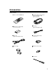
Accessories The following accessories are included with this projector. Check for them; if any item is missing, please contact your dealer. ■ Remote control unit (RM-M160G) ■ Personal computer connection cable [approx. 6.56 ft (approx. 2 m)] (D-sub, 3-row 15 pin) P l u s o n e D V I , 9 f t. ■ AA/R6-size dry cell battery (× ×2) (for checking operation) ■ Video cable [approx. 6.56 ft (approx. 2 m)] ■ Power cord [approx. 8.2 ft (approx. 2.
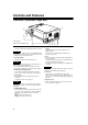
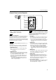
Controls and Features R IT PR ET ES NE TO YS DE HI P M TE P U W O D N LA P M KE AT ER OP E EX O PC DE U VI EN M EN TE Front Side / Top Surface / Right Side 1 9 8 7 Cabinet Design Subject to Change without notice. 1 Exhaust vents Vents for cooling fans through which warm air comes out. CAUTION • Do not block the exhaust vents, or heat will build up inside, possibly causing a fire. Also, do not touch the vents, or this could give you a low-temperature burn.
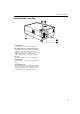
Controls and Features Left-hand Side / Rear Side UP D W O N M LA P P S Y E ID H M TE E K E R E N P TO P O E Y B D N TE TA A R T S E S E X P IT C V E M O E ID U N E N R TE p Connector panel For details, refer to “Connector Panel” on page 11. q Rear adjustable foot (for leveling the projector) It is set at the shortest position when shipped from the factory. Turn the foot to make the projector level. Adjustment can be made in the range of +1.5° and –1.
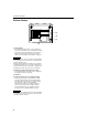
Controls and Features Bottom Surface t y u i t Air inlet (filter) Air is taken in through the filter to cool the light-source lamp. If the filter is blocked or if something that obstructs the flow of air is placed around the projector, heat may build up inside and could cause a fire. For required space, refer to “Precautions for Installation” on page 15. CAUTIONS • Be careful as paper, cloth or soft cushion could be drawn in if placed nearby.
Controls and Features Control Panel on the Projector UP WN DO LAMP PRES TONE HIDE KEYS TEMP D 1 BY OPER STAN ATE ET r PC EXIT O MEN VIDE U ENTE R e STAND BY LAMP TEMP OPERATE w q HIDE PC KEYSTONE VIDEO PRESET 1 STAND BY Indicator ON : When in stand-by mode. Blinking :When in cool-down mode. Memo About the cool-down mode: This projector has a function to cool down the heated lamp for a fixed period of time (approx. 120 seconds) after projection is finished.
Controls and Features 9 EXIT button This button will be used in the menu mode to return to the previous menu. When the main menu is displayed, this button will cause the menu to disappear. For details, refer to “Basic Menu Operation” on page 43. p PRESET button This PRESET button only works as a reset button for the direct button adjustment of the KEYSTONE button of the control panel and the DIGITAL ZOOM button of the remote control.
Controls and Features Connector Panel 4 5 UP WN DO P LAM E BY RATE D OPE STAN SET PRE STON HIDE P KEY TEM EXIT PC O MEN VIDE U R ENTE 1 R 2 Y G PB/B-Y B PR/R-Y Y/C 6 VIDEO 7 REMOTE H 8 V 3 9 IN IN 1 PC (computer) 1 input terminal (D-sub 3-row 15 pin) This is an input terminal dedicated to computer signals (RGB video signals and sync signals). Connect the display output terminal of the computer to this terminal.
Controls and Features Remote Control Unit On the remote control, the same buttons as on the control panel of the projector are provided except for the following buttons. For the same buttons, operation is the same in principle. For remote control only: DIGITAL ZOOM T/W, QUICK ALIGN., FREEZE, ZOOM T/ W, FOCUS +/–, SCREEN W/S, PC 1, PC 2, VIDEO, Y/C, DVI, COMP. See insert for instructions on Learning Remote.
Controls and Features r DIGITAL ZOOM T/W buttons A part of image can be magnified up to four times on the screen. Each time the T or W button is pressed, the image is enlarged or the enlarged image is reduced by a certain degree. (Refer to page 37.) * Images which are enlarged with the digital zoom become less clear. * Depending on the video signal source (UXGA, etc.), this button does not work. t PC buttons Use these buttons to select a device connected to the PC 1, PC 2 or DVI terminals.
Controls and Features Installing Batteries Install batteries in the remote control. If the remote control has started to work erratically, replace the batteries. 1 Open the back cover. Open the back cover in the direction of the arrow. Precautions for using batteries If batteries are used incorrectly, they may crack or leak liquid. This could cause a fire, burn, malfunction, or staining or damaging of the surroundings. Beware of the following: 2 Install the batteries.
Installing the Projector Precautions for Installation CAUTIONS 1. Before installation, do not connect the projector’s power cord. 2. Do not install the projector in the following places: • Where there is water, humidity or dust. • Where the projector may be subjected to oil, smoke or cigarette smoke. • On a soft surface such as a carpet or cushion. • Where the projector may be subjected to direct sunlight. • Where temperature is high or humidity is low.
Installing the Projector Adjusting the Inclination of the Projector The vertical angle and the leveling of the projector can be adjusted with the adjustable feet at the bottom of the projector. ■ Adjusting the vertical angle of the projector While pushing the levers on both sides upward, raise the projector. The adjustable feet automatically extend. To retract the feet, push the levers and lower the projector slowly; the projector is fixed at the position where you release the levers.
Installing the Projector Installing the Projector against the Screen The projector should be placed so that the center line of the lens is at a right angle to the screen as shown in the following figures. PC MENU VIDEO ENTER STAND BY OPERATE VOLUME TEMP HIDE LAMP PRESET ESCAPE ■ Top view KEYSTONE ■ Side view ■ Trapezoidal-distortion correctable maximum angle The projector has a function to correct the trapezoidal distortion of the projected image on the screen.
Installing the Projector Projection Distance and Screen Size • The range of projection distances that can be focused depends on the lens unit (optional) to be used. When the aspect ratio of the screen is 4:3, the range is as follows and you need to install the projector within this range. Approximate projection distance Lens type GL-M2910G 0.77 m to 4.03 m Note: There is a 7% drop (for ceiling mount) using the GL-M2915SG 1.76 m to 4.50 m GL-M2920ZG 2.77 m to 19.71 m anamorpich lens.
Installing the Projector Setting the Amount of Lens Shifting When the lens unit (optional) with the lens shifting function is used, the projected screen can be shifted up and down in position. Notes • The amount of shifting is within the range of approx. 30% to 55%. • After finishing the lens shift setting, tighten the SHIFT LOCK fixing bolt firmly so that the lens will not move. 1 2 Turn the cap on the top of the projector to open it. Loosen the SHIFT LOCK fixing bolt. Use the hex. wrench supplied.
Installing the Projector Effective Range and Distance of the Remote Control Unit The remote control unit can be used as either a wireless remote control unit or a wired one. ■ Using as a wireless remote control unit Aim the remote control unit toward the remote sensor on the front or the rear of the projector. The operable distance of the remote control unit is about 10 m for direct reception. The remote control unit can be used by having it reflected on the screen.
Installing the Projector Setting the Position Selecting Screw for Ceiling Mounting When using the projector in an upside-down, ceiling-mounted position (inverted top-to-bottom and right-to-left), the “position selecting screw for ceiling mounting” must be turned to switch to ceiling mounting. This will correct variance in color images (shading), which otherwise would occur in ceiling mounting.
Connecting to Various Devices Before connection, be sure to turn off the projector and connected devices. Read the manual which comes with each device thoroughly. Signals that Can Be Input to the Projector The following signals can be input to the projector: Note: Instructions for installing the Video ■ Video signals Processor begin on page 24. (1) Response to color systems Color systems NTSC NTSC4.
Connecting to Various Devices ■ Allowable input signals Signal PC system Vertical resolution Ver [Lines] Horizontal frequency H [kHz] 640 350 37.86 Vertical frequency V [Hz] PC98 VESA350 PC/AT PC98 640 400 24.83 56.42 DOS/V VGA 60Hz* 640 480 31.47 59.94 DVI* VGA 72Hz* 640 480 37.86 72.81 VGA 75Hz* 640 480 37.50 75.00 VGA 85Hz* 640 480 43.27 85.01 SVGA 56Hz* 800 600 35.16 56.25 SVGA 60Hz* 800 600 37.88 60.32 SVGA 72Hz* 800 600 48.08 72.
Connecting to Various Devices Connecting to Video Devices Before connection, be sure to turn off both the projector and video device. • Read thoroughly the manual that comes with each video device. • Use the supplied video cable. An video cable with an S-video (Y/C) terminal is not supplied.
Connecting to Various Devices Connecting to HDTV Devices/DVD Players Before connecting, be sure to turn off both the projector and HDTV devices/DVD players. • Thoroughly read the manual that comes with each HDTV device or DVD player. • Use separately available BNC cables to connect HDTV devices and DVD players.
Connecting to Various Devices Connecting to Devices which Control the Projector Before connection, be sure to turn off both the projector and devices to be connected. • Read thoroughly the manual that comes with each device to be connected. • By connecting a computer to the RS-232C terminal, you can control the projector. Also, you can make an infrared remote sensor extension unit and connect it to the REMOTE terminal of the projector. * Obtain connection cables as required. Use a reverse connection cable.
Connecting to Various Devices Connecting to Computer Devices Before connection, be sure to turn off both the projector and computer devices. • Read thoroughly the manual that comes with each device. ■ Connection to an IBM PC or IBM-compatible computer • Use the supplied personal computer connection cable. Also, prepare cables required for connecting the devices connected. Computer signals can either be connected directly to the projector or sent as pass-through to the Video Processor.
Connecting to Various Devices Connecting to DVI Before connection, be sure to turn off both the projector and computer devices. • Read thoroughly the manual that comes with each device. R Y G P B P H DVI (DVI-D 24pin Cable) Faroudja Video Processor V IN IN Note • Other connections are the same as in the connection example for IBM PC or IBM compatible PCs.
Connecting to Various Devices Connecting the Power Cord After all devices have been finished being connected, connect the supplied power cord. At this time, do not yet turn on the MAIN POWER switch. TE EO ME EX IT ES PR AT ER OP TO YS HID MP TE MP Insert the supplied power cord into the power input terminal of the projector.
Basic Operations ■ Lamp control settings After turning the power on, first perform the lamp control settings on the setting menu referring to “Setting and Adjusting Other Functions (OPTIONS)” on page 54. There are 3 modes in the lamp control settings. 1: NORMAL MODE (Normal) Used as a normal lamp. The projector is set to “Normal” mode at the time of purchase. * “Lamp replacement” appears on the screen when the lamp use time exceeds 1000 hours.
Basic Operations ■ Projector’s buttons STAND BY LAMP TEMP OPERATE The following describes the basic procedure for normal use of the projector. STAND BY indicator OPERATE indicator OPERATE button HIDE 1. Turning on the Power 1 KEYSTONE VIDEO PRESET MENU EXIT ENTER Turn on the MAIN POWER switch. ON [ ❙ ]:The main power turns on and the STAND BY indicator comes on.
Basic Operations ■ Projector’s buttons 2. Select the Input source to be Projected STAND BY LAMP TEMP OPERATE HIDE PC button PC KEYSTONE VIDEO button VIDEO PRESET MENU EXIT ENTER ■ Remote control unit QUICK ALIGN.
Basic Operations ■ Projector’s buttons 3. Adjust the Screen Size (Zooming) STAND BY LAMP TEMP OPERATE How to adjust the projected screen size differs depending on the lens unit (optional) you are using. GL-M2910G (without zooming function): HIDE The projected screen size cannot be changed. PC KEYSTONE VIDEO PRESET MENU EXIT ENTER PRESET button GL-M2915SG/GL-M2920ZG/GL-M2930SZG (with zooming function): Adjust the projected screen size with the following buttons on the remote control unit.
Basic Operations ■ Projector’s buttons Turning off Image (HIDE) STAND BY LAMP TEMP OPERATE HIDE button VIDEO MENU HIDE EXIT ENTER Note • When the projected image input is changed, the HIDE function is canceled and the image return. HIDE button QUICK ALIGN.
Basic Operations ■ Remote control unit QUICK ALIGN. button Quick Alignment Function (QUICK ALIGN.) QUICK ALIGN. OPERATE HIDE The Quick Alignment function automatically adjusts (sets) the screen settings of the image input from the PC1, PC2 or DVI input terminals. This can only be performed from the remote control.
Basic Operations ■ Remote control unit Displaying a Still Picture (FREEZE) While projecting an image, a still picture is obtained at any time by using the FREEZE button on the remote control. When you press the FREEZE button: QUICK ALIGN.
Menu Operations You can adjust picture quality, set functions, get information on the input video signal, etc. using the menus. From the following menu transition diagrams, you can see the overall menus and basic button operation in menu mode. Note that there are three menu modes, No signal menu mode, video menu mode and PC menu mode. When the MENU button is pressed, the projector enters one of these modes by judging the input signal being received.
Menu Operations ■ Menu Transition Diagram in Video Menu Mode Main menu in Video Menu Mode Submenus in Video Menu Mode Press 5/∞ to select an item. Press 2/3 to set or adjust the value. Press 5/∞ to select an item. Menu Press 2/3 to select Yes or No. Then, press ENTER to execute. Image adj. Image adj. Image adj. Contrast Set up Brightness Color temp.
Menu Operations . ■ Quick Reference Guide for Video Menu Mode Main Menu in Video Menu Mode (While receiving video-device-related signals) Image adj. → (Refer to page 49) Contrast: Contrast of the video image being projected can be adjusted. (–30 to +30, 0*) Brightness: Brightness of the video image being projected can be adjusted. (–30 to +30, 0*) Color: Color density of the video image being projected can be adjusted. (–30 to +30, 0*) Tint: Tint of the video image being projected can be adjusted.
Menu Operations ■ Menu Transition Diagram in PC Menu Mode Main menu in PC Menu Mode Submenus in PC Menu Mode Press 2/3 to select Yes or No. Then, press ENTER to execute. Press 5/∞ to select an item. Press 2/3 to set or adjust the value. Press 5/∞ to select an item. Menu Image adj. Image adj. 3 or ENTER Contrast Set up Brightness Color temp. Sharpness EXIT Image adj. Contrast 12 Options EXIT Language Brightness 12 Sharpness Information 1 All reset 5 5 ∞ Menu Image adj.
Menu Operations ■ Quick Reference Guide for PC Menu Mode Main Menu in PC Menu Mode (While receiving computer-related signals) Image adj. → (Refer to page 49) Contrast: Contrast of the picture image being projected can be adjusted. (–30 to +30, 0*) Brightness: Brightness of the picture image being projected can be adjusted. (–30 to +30, 0*) Sharpness: Adjust the outline of letters etc. (1 / 2 / 3 / 4 / 5, 3*) All reset: Resets above items to the factory set values.
Menu Operations Basic Menu Operation When the MENU button is pressed, the projector enters Video or PC menu mode by responding to the input signal being received. Video menu mode: Enters this mode when video-device-related signals are input from the following devices. • Video devices connected to the VIDEO IN (Y/C, VIDEO and COMP) terminals. 4 Press the cursor button 5 or ∞ to select an item in the submenu. When a “Language” has been selected in step 2, press to set the language.
Menu Operations Basic Menu Operation (Cont.) ■ Basic Button Functions in the Menu Mode Button Function MENU Enters the main menu or exits the menu mode. Cursor button 5/∞ Selects an item in the menu. Pressing ∞ or 5 will scroll the item in the menu. Cursor button 2/3 Sets or adjusts the value. PRESET If pressed while the keystone setting submenu is displayed, the value is set to “0”. EXIT Returns to the previous menu. ENTER Used to enter the submenu from the main menu.
Menu Operations Changing the Color System (Video Menu Mode Only) This function is available only in Video menu mode. The menu is only displayed when there is a signal for the AV IN (Y/C, VIDEO and COMP) terminal. Normally, use the color system in AUTO. If operation in AUTO is unstable, such as color not being shown, set to a dedicated color system in accordance with the color system of the video signal being input. 1 Press the MENU button. The main menu appears on the screen.
Menu Operations Changing the Language Display The on-screen language is set to “English” when shipped from the factory. When you want to change to another language, set it as follows. 1 Press the MENU button. The main menu appears on the screen. 2 Select “Language” with the cursor button 5 or ∞, and press 3 or the ENTER button. The “Language” submenu appears on the screen.
Menu Operations Adjusting Tracking/Phase Normally, tracking and phase adjustments are automatically carried out when a video signal is input to the projector for the first time, or when the QUICK ALIGN. button on the remote control is pressed. However, you can manually adjust the tracking and phase on the menu. If a wide stripe appears on the screen, adjust the lateral size of the picture image and the display area (tracking adjustment) so the stripe disappears.
Menu Operations Set up for Watching Image Software (Video Menu Mode Only) This unit has a function which allows you to project movies, which were recorded on film, in the best possible conditions. (Function to convert 2-3 pull-down interlace scans to progressive scans) Normally use set to AUTO. 1 Press the MENU button. The main menu appears on the screen. 2 Select “Set up” with the cursor button 5 or ∞, and press 3 or the ENTER button. The “Set up 1” submenu appears on the screen.
Menu Operations Adjusting Picture Quality In the “Image adj.” submenu, adjust brightness, contrast, sharpness, etc. to obtain the desired picture quality. Note that the adjustment items differ in Video menu mode and PC menu mode. 1 Press the MENU button. The main menu appears on the screen. 2 Select “Image adj.” with the cursor button 5 or ∞, and press 3 or the ENTER button. The “Image adj.” submenu appears on the screen. Video submenu PC submenu Image adj.
Menu Operations . Image adj. All reset? Yes 5 No Press the EXIT button to return to the previous menu or press the MENU button to exit the menu mode. Memo In some adjustments, the level bar changes according to the set value. (The setting value is also displayed at the left of the level bar.) Adjusting Color temperature 1 Note: color temperature has been set by Faroudja.Do not readjust. Press the MENU button. The main menu appears on the screen. 2 Select “Color temp.
Menu Operations Adjusting the Video Screen/Menu Position The position of the video screen and the menu on the video screen can be adjusted. You can finely adjust the video screen position. The menu will move widely on the video screen. 1 Press the MENU button. The main menu appears on the screen. 2 Select “Set up” with the cursor button 5 or ∞, and press 3 or the ENTER button. The “Set up 1” or “Set up” submenu appears on the screen.
Menu Operations Changing the Image Gamma/Aspect Ratio (Video Menu Mode Only) The image Gamma (Down, Cinema or Up) and the aspect ratio (4:3 or 16:9) are selectable in Video menu mode. 1 Press the MENU button. The main menu appears on the screen. 2 Select “Set up” with the cursor button 5 or ∞, and press 3 or the ENTER button. The “Set up 1” submenu appears on the screen.
Menu Operations Changing the Image Size - Resize Function (PC Menu Mode Only) The picture image projected can be selectable with the 1 Press the MENU button. Resize function which is available only in PC menu mode. You can choose the video image size projected from the following: (Factory setting is “Aspect”.) “1:1”: The image is displayed at the input resolution.
Menu Operations Setting and Adjusting Other Functions (OPTIONS) Various functions are provided as shown in the “Options 1” and “Options 2” submenus. You can set or adjust each function, as required. 1 Press the MENU button. The main menu appears on the screen. 2 Select “Options” with the cursor button 5 or ∞, and press 3 or the ENTER button. The “Options 1” submenu appears on the screen.
Menu Operations Adjustment item Button Adjustment content 2 or 3 Sets whether to clear the menu display automatically or not. 15sec* : Clears the display automatically in about 15 seconds. ON : Does not automatically clear the menu display. 2 or 3 Sets whether to show the line display (Y/C, VIDEO, COMP, PC1, PC2 or DVI) on top right of the screen or not when the VIDEO or PC button is pressed. 5sec* : Shows the line display for about 5 seconds. OFF : Does not show the line display.
Menu Operations Getting Information You can get information on the input signal, accumulated used hours of light-source lamp, etc. 1 Press the MENU button. The main menu appears on the screen. 2 Select “Information” with the cursor button 5 or ∞. The “Information” will be displayed in the main menu. *No submenu can be selected. Video main menu PC main menu Menu Image adj. Menu Input Setting Switcher Color temp. Source VIDEO CH.
Replacing the Fuse A fuse is used to protect the power source of the projector. If the fuse is blown, replace it. When the power switch is turned on but no power is supplied to the projector, check the fuse. If there are any unclear points, contact the dealer where you purchased your projector, or consult the Service center. CAUTION • When replacing the fuse, use the same rating and type (12 A 250 V). Otherwise, a fire may occur and/or the projector may be damaged.
Replacing the Light-Source Lamp ■ Light-source lamp and lamp use time The light-source lamp has a service life of approximately 1000 hours. [Average lamp life: 1000 hours (brightness half-life)] When the light-source lamp approaches the end of its service life, degradation progresses rapidly. In NORMAL MODE, arrange for a new lamp (lamp unit) or replace the lamp after 900 hours. Depending on the usage conditions, the replacement time may be shorter.
Replacing the Light-Source Lamp ■ Projecting after the lamp has been used for more than 1000 hours (LIGHT OUTPUT CONTROL MODE) (LAMP POWER CONTROL MODE) Accumulated used hours of the light-source lamp 1000 hours 1900 hours 2000 hours 2010 hours When the lamp use time reaches 1000 hours: “1000h” and “Lamp replacement” appear on the screen. * The messages will disappear when any button is pressed. * The time after which the display appears can be set with the OSD menu.
Replacing the Light-Source Lamp ■ Be sure that the power cord is unplugged from the wall outlet. 1 Remove the lamp-replacement opening cover by loosening screws. Loosen the two screws with a flat-end screwdriver. Note Screw • The screws are fitted so that they do not come off the lampreplacement opening cover. Lamp-replacement opening cover Be careful not to damage the claw. 2 Loosen the screws, raise the handle, and pull out the light-source lamp.
Replacing the Light-Source Lamp 3 Insert the new light-source lamp fully inside and fasten the screws. Light-source lamp Fasten the two screws with a flat-end screwdriver. CAUTION • Do not touch the glass surface of the light-source lamp directly with your hand as well as staining it. If you touch with a bare hand, oils and other substances on your hand may adhere to the lamp, possibly preventing it from performing as specified and therefore giving a shortened lamp life, a darkened screen, etc.
Replacing the Light-Source Lamp ■ Resetting the Lamp Use Time After replacing with a new light-source lamp, reset the lamp-time counter inside the projector to clear the accumulated lamp time to zero (0). After resetting, a new count will start for the new light-source lamp. 1 ■ Projector’s button STAND BY LAMP TEMP OPERATE 4 HIDE PC 2 1 PC 1 Momentary press the PC button.
Cleaning and Replacing the Filter Cover Clean the filter regularly. If the filter is heavily stained and does not clean, or if it is damaged, replace the filter with a new filter. Otherwise, dirt may get inside and appear on the screen, preventing you from fully enjoying the video image. If dirt gets inside or if you need information about the filter, consult authorized dealer where you purchased the projector or the nearest Service Center. 1 Turn off the MAIN POWER switch.
Troubleshooting Solutions to common problems related to your projector are described here. If none of the solutions presented here solves the problem, unplug the projector and consult an authorized dealer or Service Center. Symptom Power is not supplied. Probable cause • Is the power cord disconnected? • Is the MAIN POWER switch turned on? • Is the fuse blown? Corrective action • Insert the power cord (plug) firmly. • Turn on the MAIN POWER switch. Page 30 32 Light is not emitted, or light level is low.
Troubleshooting Symptom A part of image is magnified. Color is poor or unstable. Probable cause • Was the DIGITAL ZOOM T button on the remote control pressed? • Is picture quality (color density, etc.) adjusted correctly? • Is the correct color system selected? Corrective action • Press the PRESET button to restore the original video screen. • Adjust picture quality on the menu. • Set the color system to AUTO or to the correct dedicated color system. • Are signals (scanning frequency, etc.
Warning Indication If something abnormal has occurred with the projector, the warning status will be indicated by the combination of lighting the indicators on the control panel as shown in the following table. Then, the projector automatically stops projection and runs the cooling fan for about 120 seconds. Warning indication table: Indicator No. Warning content LAMP 1 Blink 2 Blink 3 Blink TEMP STAND BY Blink Blink The light-source lamp has suddenly gone off during projecting an image.
Warning Messages The following shows the warning messages that can be displayed on the screen. When a warning message is displayed, take the corrective action described here. Message PC 1 No Input PC 1 Cause Corrective action • Connect a device to the selected • No device is connected to the terminal. input terminal. • The terminal is connected but no • Operate the connected device and output a signal. signal is output from the connected device.
Warning Messages Message D.ZOOM Lamp replacement EXIT Warning Lamp replacement EXIT Cause Corrective action • When the DIGITAL ZOOM button • Digital-zoom function does not is pressed for the video signals work for the inputted video that cannot be zoomed (UXGA signals. 60Hz, SXGA 60Hz.), this To use the this function, input the message appears for a few video signals that can be digitally seconds to notify that the image zoomed. cannot be digitally zoomed.
Warning Messages Message 1000 h Lamp replacement EXIT Lamp replacement EXIT Warning Lamp replacement EXIT Cause Corrective action Page Displayed when the lamp control • Arrange for a new lamp (lamp setting is set to LIGHT OUTPUT unit) or replace the lamp early. CONTROL MODE (LOC) or LIGHT POWER CONTROL MODE (LPC) and the lamp use time display is turned [ON] with the OSD menu • Displayed when the lamp use time exceeds 1000 hours.
Specifications ■ Optical mechanism system • Projection method D-ILA® (Direct Drive Image Light Amplifier) method (Reflective-type active-matrix method) • D-ILA® device 0.9" (2.3 cm) measured diagonally (1365 pixels × 1024 pixels) × 3 (Total number of pixels : 4,193,280) • Projecting lens GL-M2910G: GL-M2915SG: GL-M2920ZG: GL-M2930SZG: 1:1 1.5:1 (with ±2% zooming/shift function) × 1.5 zoom lens (2:1 to 3:1) (zooming function) × 1.9 zoom lens (2.9 to 5.
Specifications ■ General • Power requirements 120 V AC, 50/60 Hz • Power consumption 7A • Allowable operation temperature 41°F to 95°F (+ 5°C to + 35°C) • Allowable relative humidity 20% to 80% (no condensation) • Allowable storage temperature 14°F to 140°F (– 10°C to + 60°C) • Dimensions Approx. 20" × 10-1/2" × 15-1/2" (Approx. 505 mm × 265 mm × 393 mm) [Carrying band, Excluding protrusions] (Width × Height × Depth) • Weight Approx. 32.12 lbs. (Approx. 14.
Specifications Outside dimensions ■ Top Unit: inch 22.430 ENTER EXIT MENU PRESET VIDEO KEYSTONE PC HIDE OPERATE LAMP TEMP 19.300 18.444 STAND BY 5-1/4 (133) ■ Front ■ Side 19.300 2-1/8 (53) 111.703 10.605 11.703 22.
Specifications Pin assignment (Specifications for terminals) ■ Y/C terminal Pin number 4 3 1 2 Signal name 1 GND (Y) 2 GND (C) 3 Y 4 C ■ RS-232C terminal Pin number Signal name Pin number Signal name 9 8 7 6 5 4 3 2 1 1 N/C 6 N/C 2 RD 7 N/C 3 TD 8 N/C 4 N/C 9 N/C 5 GND ■ PC1 terminal/PC OUT terminal Pin number 11 7 6 12 13 14 15 1 2 8 3 4 5 9 10 Signal name Pin number Signal name 1 Red 9 N/C 2 Green 10 GND (SYNC) 3 Blue 11 GND 4 N/C 12 N/C 5 N/
RS-232C external control By connecting a computer to the RS-232C terminal, you can control the projector. Use a reverse connection cable as the RS232C connection cable. The commands to control the projector and the response data against the received commands are explained here. For further information, please consult the dealer where you purchased your projector or consult the Service Center. 1.
RS-232C external control 2-3 Parameters used for the data format The following three kinds of parameters are prepared for the control command and response data. (1) Numeric value Designates the 2-byte hexadecimal value with the sign as the 4-digit (byte) characters. Designation allowable range: “8000” to “7FFF” (2) ON/OFF Designates the status (ON/OFF) of the projector, such as POWER and HIDE. Character Hex.
Appendix ■ Relationship between Projection Distances and Projection Screen Sizes Notes Note: There is a 7% drop (for ceiling mount) using the anamorphic lens. Calculate 7% of the through distance. • The relationship between the projection distances and projection screen sizes differs depending on the lens unit (optional) you are using. • The projection distance and projection screen sizes listed here are only for a guide. Use them as reference when setting the projector.
Appendix For lens unit GL-M2920ZG (2 to 3:1): Approximate projection distance Projection screen size (Diagonal length) 40" (approx. 101.6 cm) 42" (approx. 106.7 cm) 50" (approx. 127.0 cm) 60" (approx. 152.4 cm) 70" (approx. 177.8 cm) 80" (approx. 203.2 cm) 100" (approx. 254.0 cm) 150" (approx. 381.0 cm) 200" (approx. 508.0 cm) 240" (approx. 609.6 cm) 250" (approx. 635.0 cm) 300" (approx. 762.0 cm) 310" (approx. 787.4 cm) 320" (approx. 812.8 cm) 330" (approx. 838.2 cm) 340" (approx. 863.6 cm) 350" (approx.
WARRANTY LIMITED WARRANTY Faroudja Laboratories, Inc. ("Faroudja") warrants that its products will be free of defects in workmanship and material and conform substantially to published specifications under normal use and service. This warranty is made to the first purchaser of the products and extends for twelve (12) months from the date of sale. The warranty for the light source lamp is 90 days.