A subsidiary of Alanco Technologies, Inc. SecurStor Astra ES Administration Guide Revision: 1.0 Contact Information Excel Meridian Data, Inc. 3220 Commander Drive Ste 101 Carrollton, TX 75006-2564 Toll Free: (800) 995-1014 Phone: (972) 980-7098 Fax: (972) 980-0375 sales@emdstorage.com support@emdstorage.com http://www.emdstorage.
Copyright ©2007 This guide and any accompanying software and firmware are copyrighted. No parts of this publication may be reproduced, stored on a retrieval system, or transmitted, in any form or by any means, electronic, mechanical, photocopy, recording, or otherwise, without prior written consent except for copies retained by the purchaser for backup purposes. All rights Reserved. Notice We make no warranties with respect to this documentation either express or implied and provide it "as is".
(this page intentionally left blank) SECURSTOR ASTRA ES 3
Table of Contents Chapter 1: Introduction to Astra ES ....................................................................... 7 About This Manual ................................................................................................... 7 Astra ES Overview ................................................................................................... 8 Architectural Description .......................................................................................... 9 Specifications ..........
Cache Policy ......................................................................................................... 96 LUN Affinity .......................................................................................................... 96 Capacity Coercion .................................................................................................. 97 Initialization.......................................................................................................... 98 Hot Spare Drive(s) ....
(this page intentionally left blank) 6 EXCEL MERIDIAN DATA
Chapter 1: Introduction to Astra ES This chapter covers the following topics: • About this Manual • Astra ES Overview • Architectural Description • Specifications Thank you for purchasing the SecurStor Astra ES disk array subsystem from Excel Meridian Data. About This Manual This Product Manual describes how to setup, use and maintain the Astra ES disk array subsystem. It also describes how to use the embedded Web-based Astra ES Management GUI software.
Astra ES Overview Astra ES provides data storage solutions for applications where high performance and data protection are required. The failure of any single drive will not affect data integrity or accessibility of the data in a RAID protected logical drive. A defective drive may be replaced without interruption of data availability to the host computer. If so configured, a hot spare drive will automatically replace a failed drive, securing the fault-tolerant integrity of the logical drive.
Architectural Description The Astra ES is a Fibre Channel or Serial Attached SCSI (SAS) host, SAS+SATA disk, subsystem suitable for Direct Attached Storage (DAS), Storage Area Network (SAN), and Expanded Storage. Only hard disk drives from Excel Meridian Data are approved for use in this solution. All enclosures include a mid-plane, RAID controller, power and cooling units, and enclosure processor all in one cable-less chassis design.
Configurable RAID stripe size: 64 KB, 128 KB, 256 KB, 512 KB, and 1 MB stripe size per logical drive. Background task priority tuning: Adjustment of minimum I/O reserved for server use during all background tasks. Hot spares: Multiple global or dedicated hot-spare drives with revert option. Maximum LUNs per subsystem: 256 in any combination of RAID levels. Maximum LUNs per array: 32 logical drives (LUNs). Supports LUN carving by allowing an array to be divided into multiple logical drives.
Warranty and Support Warranty: Five years complete system limited warranty. Contact Excel Meridian Data for details. Support: Email and phone support. FCC Statement This device complies with Part 15 of the FCC Rules. Operation is subject to the following two conditions: (1) this device may not cause harmful interference, and (2) this device must accept any interference received, including interference that may cause undesired operation. CE Statement Warning: This is a class A product.
(this page intentionally left blank) 12 EXCEL MERIDIAN DATA
Chapter 2: Astra ES Installation This chapter covers the following topics: • Unpacking the Astra ES (below) • Mounting in a rack • Installing disk drives • Making management connections • Connecting power Unpacking the Astra ES The Astra ES box contains the following items: • Astra ES Unit • RJ11-to-DB9 serial data cable • Quick Start Guide • 10ft CAT6 RJ45 network cable(s) • This Administration Guide • • Rail kit 5ft Power cords (4) (2 US and 2 European) • CD with AstraPath, Produc
Mounting Astra ES in a Rack The subsystem installs in the rack using the supplied mounting rails. Cautions • At least two persons are required to safely lift, place, and attach the Astra ES enclosure into a rack system. • Do not lift or move the Astra ES enclosure by the handles, power supplies or the controller units. Hold the enclosure itself. • Do not install the Astra ES enclosure into a rack without rails to support the enclosure.
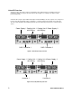
Rack f ront post Rack back post Rail adjustment screw Rail adjustment screw Front f lange Rear f lange Rail Plate Rail attaching screw (not included) Inside of post Rail attaching screw (not included) Inside of post Figure 3: Rackmount assembly Installing Disk Drives Your solution is sold with SAS or SATA (or a combination of both) hard disk drives. Excel Meridian Data will not support any solution populated with disk drives not purchased through Excel Meridian Data.
Making Management and Data Connections For Serial Attached SCSI setup skip to the next section. Fibre Channel Host Astra ES models can have one or two RAID controllers. Each controller has an Ethernet (RJ45) Management Port connector that enables you to monitor the Astra ES over your network using the Astra ES Management GUI Software. Astra ES supports HTTP(S) and Telnet protocols. The Astra ES RAID controller has two 4-Gb Fibre Channel (FC) connections for the data ports.
On the Astra ES controller, connect one of the Fibre Channel data ports to your Fibre Channel switch. To establish the management path: 1. On the Astra ES controller, connect the Management Port to your network switch. 2. Connect the Host PC’s or Server’s standard NIC to your network switch. Configuring JBOD expansion: To expand the number of disk drives: 1.
Serial Attached SCSI Host Astra ES models can have one or two RAID controllers. Each controller has an Ethernet (RJ45) Management Port connector that enables you to monitor the Astra ES over your network using the Astra ES Management GUI Software. Astra ES supports HTTP(S) and Telnet protocols.
Configuring Cascaded Storage Cascaded storage requires: • One SAS HBA card in the Host PC or Server • A network switch • A network interface card (NIC) in the Host PC or Server To establish the data path: 1. On the Astra ES controller, connect a SAS data port or a SAS data/cascade port to your SAS HBA card. 2. Connect the data/cascade port (a subtractive-routed port) of the first Astra ES RAID header to the data port (a table-routed port) on the second Astra ES RAID header. 3.
Connecting the Power Plug the power cords and switch on both power supplies on. When the power is switched on, the LEDs on the front of the Astra ES will light up.
Chapter 3: Management with Astra GUI This chapter covers the following topics: • Logging into Astra GUI • Exporting the User Database • Selecting a language • Importing a User Database • Perusing the interface • Updating the Firmware • Logging out of Astra GUI • Restoring the Factory Defaults • Working with the Storage Network • Clearing statistics • Working with Subsystems • • Managing the User Database Shutting down and Restarting the subsystem • Managing the Ethernet Network in
Whether you select a regular or a secure connection, your login to Astra GUI and your user password are always secure. 3. When the log-in screen (Figure 1) appears: • Type administrator in the User Name field. • Type admin in the Password field. • Click the Login button. The User Name and Password are case sensitive. 4. Click the Login button. Selecting a Language Astra GUI displays in English, German, French, Italian, Japanese, Chinese Traditional, Chinese Simple, and Korean. 1.
Using Tree View Tree View enables you to navigate around all components of the Subsystem, including Fibre Channel or SAS management, network and service management, RAID controller, enclosure, physical drives, disk arrays, logical drives, and spare drives. The figure below shows the components of Tree View. The Administrative Tools section is different for the Super User than for other users. The remainder of the Tree is the same for all users.
Figure 8: Clicking logout in the header bar Clicking Logout brings you back to the Login Screen. After logging out, you must enter your user name and password in order to log in again. Working with the Storage Network When you log into Astra Management GUI, you access a specific Astra ES subsystem. The Storage Network feature enables you to access all of the Astra subsytems with a Management Port connection to your network. Each Astra ES subsystem is identified by its Management Port IP address.
• Viewing and Clearing event logs • Viewing current Background activities • Running Media Patrol • Running PDM • Viewing, Deleting and Scheduling activities • Viewing, Setting, Renewing and Releasing the Lock status Viewing Subsystem Information To view information about a subsystem, click the Subsystem the subsystem information. icon in Tree View. Management View displays Setting an Alias for the Subsystem An alias is optional. To set an alias for this subsystem: 1.
3. • Severity – Information, Warning, Minor, Major, Critical, and Fatal. The severity level is user-specified. • Time – Time and date of the occurrence • Description – A brief description of the event Click on the link at the top of the column by which you want to sort the events. After you click on the item, a triangle icon appears. • If the triangle points upward, the column is sorted low-to-high or old-to-new. • If the triangle points downward, the column is sorted high-to-low or new-to-old.
5. In the Save dialog box, name the file, navigate to the folder where you want to save the log file, and click the Save button. Clearing NVRAM Events To clear the NVRAM event log: 1. In Tree View, click the Subsystem icon. 2. In Management View, click the Events tab dropdown menu and select System Events in NVRAM. 3. Click the Clear Event Log button. 4. In the Confirmation dialog box, type confirm and click the OK button.
Running Background Activities To run a background activity from the Background Activities tab: 1. In Tree View, click the Subsystem 2. In Management View, click the Background Activities tab and select one of the following from the dropdown menu. • Media Patrol • Rebuild • PDM • Transition • Initialization • Redundancy Check icon. 3. In the next screen, make the choices as requested. 4. Click the Start button.
3. In the Scheduler dialog box, check the Enable This Schedule box. 4. Select a start time (24-hour clock). 5. Select a Recurrence Pattern. • Daily – Enter the number of days between events. • Weekly – Enter the number of weeks between events and select which days of the week. • Monthly – Select a calendar day of the month (1 – 31). If you select a higher number than there are days in the current month, the actual start date will occur at the beginning of the following month.
The lock prevents other sessions (including by the same user) from making a configuration change to the controller until the lock expires or a forced unlock is done. You can set the lock to last from one minute to one day. To set the lock for this subsystem: 1. Click the Subsystem 2. Click the Lock tab in Management View. icon Tree View. 3. Click the Lock option. 4. Enter a time interval between 1 and 1440 minutes (one day) that you want the lock to stay active. 5. Click the Submit button.
Making User Settings To change settings of other users: 1. Log into Astra GUI as the Administrator or a Super User. 2. Click the Subsystem 3. Click the Administrative Tools 4. Click the User Management 5. On the Information tab, click the link of the user whose settings you want to change. icon in Tree View. icon. icon. The Settings screen for the selected user displays. 6. 7. Make the following settings as needed. • Check the Enable box to enable this user.
Changing Another User’s Password To change a user’s password: 1. Log into Astra GUI as the Administrator or a Super User. 2. Click the Subsystem 3. Click the Administrative Tools 4. Click the User Management 5. In the list of users, click the link of the user whose settings you want to change. icon in Tree View. icon. icon. The Settings screen for the selected user displays. 6. Click the Password tab in Management View. 7. Enter the new password in the New Password field. 8.
• Maintenance – Allows the user to perform maintenance tasks including Rebuilding, PDM, Media Patrol, and Redundancy Check • Power – Allows the user to create (but not delete) disk arrays and logical drives, change RAID levels, change stripe size; change settings of components such as disk arrays, logical drives, physical drives, and the controller.
To make changes to the Subsystem Management Port settings: 1. Click the Subsystem icon in Tree View. 2. Click the Administrative Tools 3. Click the Network Management 4. Click the Port Configuration link in Management View. 5. To enable DHCP, check the DHCP box. icon. icon. When DHCP is NOT enabled, enter: 6. • Primary IP address • Primary subnet mask • Default gateway IP address • Enter a primary DNS server IP address. Click the Submit button.
2. Click the Administrative Tools 3. Click the Fibre Channel Management icon. 4. Click the Node tab in Management View. icon. The current node (data port) settings the Controller are shown, including: • WWNN – World Wide Node Name • Supported Features – Class of service • Maximum Frame Size – 2048 bits • Supported Speeds – 4 Gb/s, 2Gb/s, or 1 Gb/s Viewing Fibre Channel Port Settings To view the current Fibre Channel port settings: 1. Click the Subsystem icon in Tree View. 2.
Port Setting Information The table below shows the type of attached topology you will achieve based on your connection type and the configured topology you select. Fibre Channel Attached Topology Configured Topology Connection Type N-Port NL-Port Switch Fabric Direct Public Loop Direct Point to Point Private Loop Example 1: If you connect the Astra ES to a Fibre Channel switch and select NL-Port topology, you will create a Public Loop attached topology.
• Transceiver Code – Defines the method to interpret the transceiver type and compatibility options • Serial Encoding – Serial encoding algorithm • Bit Rate – In gigabits per second • Link Length – The maximum link length depending the type of fiber • Vendor Name – Vendor name of the SFP transceiver • Vendor OUI – Organizational Unique Identifier, SFP vendor’s IEEE company ID • Vendor Part Number • Vendor Revision • Vendor Serial Number • Manufacturing Date – Code with 2 digits each for y
2. Click the Administrative Tools 3. Click the SAS Management icon. icon. The port information appears the screen. • Channel ID • Port Type • Link Status • Link Speed • SAS Address • Cable Signal Strength – Adjustable under Port Settings Modifying SAS Port Settings A SAS Controller can have one or two SAS channels.
Adding an Initiator To add an initiator to the Astra ES initiator list: 1. Check the box to the left of the initiator. 2. Click the Add to Initiator List button. Managing Storage Services Storage services deal with initiators and LUN mapping for Fibre Channel models and for Serial Attached SCSI models. LUN masking is the process of applying a LUN Map so that each initiator can only access the LUNs specified for it.
Enabling LUN Masking To enable the LUN Masking: 1. Click the Subsystem 2. Click the Administrative Tools icon in Tree View. 3. Click the Storage Services 4. Click the LUN Map tab in Management View. 5. Click the LUN Masking Enabled box. 6. Click the Submit button. icon. icon. Adding a LUN Map To edit the LUN Map: 1. Click the Subsystem 2. Click the Administrative Tools icon in Tree View. 3. Click the Storage Services 4.
The Email sends notification messages to users. To modify Email service settings: 1. Click the Subsystem icon in Tree View. 2. Click the Administrative Tools 3. Click the Email Setting link in Management View. 4. Enter the IP address for your SMTP server. 5. Enter server port number for your SMTP server. icon. 25 is the default. 6. Select Yes to enable SMTP authentication or No to Yes. 7. If you selected Yes for SMTP authentication, enter a Username and Password in the fields provided. 8.
Starting or Restarting SLP service To start or restart the SLP service, click the Start or Restart button. Managing Web Server Settings Astra ES’s Web Server service connects the Astra GUI to the Astra ES subsystem though your browser. To modify Web Server settings: 1. Click the Subsystem 2. Click the Administrative Tools icon in Tree View. 3. Click the Web Server Setting link in Management View. 4. Enter the HTTP Port number. icon. 80 is the default. 5. Enter Session Time Out interval.
8. Click OK in the confirmation box to restart the Telnet service with your changes. Changing the Startup Setting 1. 2. Under Startup Type: • Click on the Automatic option to start the service automatically during system startup. Recommended. • Click on the Manual option to start the service manually (the service does not start during system startup). Click on the Submit button. Stopping Telnet service To stop the Telnet service: 1. Click the Stop button. 2. Click OK in the confirmation box.
4. Click OK in the confirmation box. Changing the Startup Setting 1. 2. Under Startup Type: • Click on the Automatic option to start the service automatically during system startup. Recommended. • Click on the Manual option to start the service manually (the service does not start during system startup). Click on the Submit button. Stopping SNMP service To stop the SNMP service: 1. Click the Stop button. 2. Click OK in the confirmation box.
Managing Netsend Settings Astra ES’s Netsend service sends Astra subsystem events in the form of popup messages to your Host PC and other networked PCs. This service is normally Stopped and set to Manual start. To change the Netsend settings: 1. Click the Subsystem icon in Tree View. 2. Click the Administrative Tools 3. Click the Netsend link. 4. Click the Start button to start the Netsend service. 5. Click the Submit button. icon. Adding Netsend recipients To add a Netsend recipient: 1.
The Export action saves a text file a designated folder the Host PC. From there, you can import the User Database file to other Astra ES subsystems. To export the User Database file: 1. Click the Subsystem icon in Tree View. 2. Click the Administrative Tools 3. Click the Export link in Management View. 4. Click the Export button. 5. In the Opening export dialog box, click the Save to Disk option. 6. Click the OK button. icon.
Note The Decryption box is grayed out. Decryption is always enabled. Updating the Firmware This procedure is covered in a later chapter of this manual. Firmware must be obtained from Technical Support. Restoring Factory Defaults Astra ES includes a function to restore the default settings to its Firmware and Software settings. Caution The action of restoring default settings can disrupt your Astra ES functions.
Shutting Down the Subsystem You can only do part of this function in Astra GUI. Additional action is required, as described below. To shutdown the subsystem: 1. Click the Subsystem 2. Click the Administrative Tools icon in Tree View. 3. Click the Shutdown link in Management View. icon. A Shutdown or Restart tab will appear. 4. On the Shutdown or Restart tab, select Shutdown from the dropdown menu. 5. Click the Submit button. 6.
The controller information appears under the Information tab in Management View. Controller information includes: • Controller ID (1 or 2) • Alias, if assigned • Model, if applicable • Status – OK means normal • Readiness Status – Active or Standby • Locate – Click on the button to locate the controller. See below Astra ES subsystems with only one controller will always show that the second controller is ―Missing.
You can set or adjust the following items: • Alias, if assigned • Coercion, enable or disable • Coercion Method • SMART – Self-Monitoring, Analysis, and Reporting System for physical drives.
6. Click the Submit button. The changes take effect immediately. Clearing an Orphan Watermark An Orphan Watermark condition is the result of a disk drive failure during an NVRAM RAID level migration on a disk array. To clear an Orphan Watermark: 1. Click the Subsystem icon in Tree View. 2. Click the Controllers 3. Click the Controller 4. Click on the Clear tab in Management View. 5. Click the Submit button. icon. icon. The changes take effect immediately.
1. Click the Subsystem icon in Tree View. 2. Click the Enclosures icon. 3. click the Topology tab in Management View.
The Enclosure–Battery tab displays information about the cache backup battery (or batteries) in the Astra ES subsystem enclosure. To check the batteries: 1. Click the Subsystem icon in Tree View. 2. Click the Enclosures icon. 3. Click the Enclosure 4. Click the Battery tab in Management View. icon. Battery Notes Each battery works with a controller. If the battery is present in the subsystem but the corresponding controller is not present, the battery will not appear in the interface.
2. Click the Enclosures icon. 3. Click the Enclosure 4. Click the Buzzer tab in Management View. 5. From the Buzzer tab dropdown menu, select Settings. 6. Check the Buzzer Enabled box. 7. Check the Test Buzzer box. 8. Click the Submit button. icon. The buzzer will sound for one minute.
• Command Queuing (for disk drives that support Command Queuing) • From the DMA Mode dropdown menu, select a DMA mode. For SAS drives, check the boxes to enable: 7. • Write Cache • Read Look Ahead Cache • Command Queuing (for disk drives that support Command Queuing) • Read Cache Click the Submit button. The functions you enable here depend on whether the physical drives support those functions. Viewing Physical Drive Information To view physical drive information: 1.
7. Type an alias into the Physical Drive Alias field. Maximum of 32 characters. Use letters, numbers, space between words, and underscore. An alias is optional. 8. Click the Submit button. Clearing Stale and PFA Conditions The Clear tab only appears when those conditions are present. • Stale – The physical drive contains obsolete disk array information. • PFA – The physical drive has errors resulting in a prediction of failure.
2. Click the Enclosures icon. 3. Click the Enclosure 4. Click the Physical Drives icon. 5. Click on a Physical Drive icon. 6. Click the Force Offline/Online tab in Management View. 7. Click the Submit button. 8. In the confirmation box, type the word confirm in the field provided. 9. Click the OK button. icon.
5. • Disk Arrays – The number of physical drives in the disk array, their slot numbers, configurable capacity, and the number of logical drives to be created • Logical Drives – The ID number of the logical drive(s), their RAID level, capacity, and stripe size • Spare Drives – The physical drive slot number of the dedicated hot spare assigned to this disk array.
The Disk Array Advanced Creation option enables you to directly specify all parameters for a new disk array. One logical drive will be made automatically when you create the disk array. If you select less than the total available capacity, you can use the remaining space to create additional logical drives at a later time. If you are uncertain about choosing parameters for your disk array, use the Express or Automatic option to create your disk array. To create a new disk array: 1.
Note This function does not automatically create a hot spare drive. After the disk array is created, you can create a hot spare drive for it. Deleting a Disk Array The Disk Arrays–Delete tab enables you to delete existing disk arrays. Caution If you delete a disk array, you also delete any logical drives that belong to it, along with the data in those logical drives. Back up any important data before deleting a disk array. To delete a disk array: 1. Click the Subsystem icon in Tree View. 2.
Adjustable Items • Alias – Optional. • Media Patrol – Enabled or disabled. • PDM – Enabled or disabled. Managing Disk Array Settings To modify Disk Array settings: 1. Click the Subsystem icon in Tree View. 2. Click the Disk Arrays icon. 3. Click the Disk Array 4. Click the Settings tab in Management View. 5. Optional. Enter an alias in the Disk Array Alias field. icon. Maximum of 32 characters. Use letters, numbers, space between words, and underscore. An alias is optional. 6.
15. Review the results. If there is remaining space the disk array, you can create another logical drive, following the steps above. Each logical drive can have a different set of parameters. 16. Click the Next button when you are done. A new window displays with the disk array information and the proposed logical drives with their parameters. 17. Click the Submit button create the logical drives. The new logical drive appears in the Logical Drive List the Information tab.
6. When you are done, click the Next button. 7. Select a new RAID Level, if desired. 8. To expand the disk array's capacity, check the Expand Capacity box. 9. If you checked the Expand Capacity box, enter a number into the Capacity field and select the appropriate unit of measure (MB, GB, TB). 10. Under Capacity Usage, highlight the logical drive whose RAID level you want to change or whose capacity you want to expand. 11. Click the Update button. The logical drive changes to reflect your choices.
1. Click the Subsystem icon in Tree View. 2. Click the Disk Arrays icon. 3. Click the Disk Array 4. Click the Background Activities tab in Management View. 5. From the dropdown menu the Background Activities tab, choose Start PDM. 6. In the next screen, select the Source and Target physical drives. icon. The suspect physical drive is the source. The replacement physical drive is the target. 7. Click the Start button.
9. Click the Refresh button in your Browser. The drives appear in their new locations and disk array status displays OK. Managing Logical Drives Logical drives are made from disk arrays. In the Tree, you can see a graphic representation of the logical drives that belong to each array. You can see a summary of all logical drives in the subsystem under Logical Drive Summary.
4. Click the Logical Drives 5. Click the Logical Drive icon icon. To specify an Alias or set the Read and Write Policies, click the Settings tab. Logical Drive Synchronization Synchronization is an automatic procedure applied to logical drives when they are created. Yes means the logical drive was synchronized. Adjustable Items • Alias – Optional. • Read Policy • Write Policy • Preferred Controller ID Viewing Logical Drive Statistics To view information for a single logical drive: 1.
Caution When you initialize a logical drive, all the data the logical drive will be lost. Backup any important data before you initialize a logical drive. Initialize a Logical Drive: 1. Click the Subsystem icon in Tree View. 2. Click the Logical Drive Summary 3. Click the icon. icon of the logical drive you want to Initialize. You can also start Initialization from the Subsystem icon Background Activities tab 4. Click the Background Activities tab in Management View. 5.
4. Click the Logical Drives icon 5. Click the Logical Drive 6. Click the Check Table tab in Management View. 7. Click the option for the table you want to see. icon. The default is All tables. If there are entries, they are listed as follows: • Entry Number – A number assigned to each block of entry. • Table Type – Read Check, Write Check or Inconsistent Block (see below). • Start Logical Block Address – LBA of the first block for this entry.
• Fibre Channel – A Fibre Channel initiator name is the World Wide Port Name of the device and is composed of a series of eight, two-digit hexadecimal numbers. • SAS – A SAS initiator name is the SAS address of the HBA card in the Host PC. • Alias – Optional. A common name for an iSCSI initiator • Symbolic Name – Optional.
• There must be an unconfigured physical drive available for selection as a spare drive. • Be sure the unconfigured physical drive has adequate capacity to replace the largest drive in the disk array. To create a spare drive: 1. Click the Subsystem 2. Click the Spare Drives icon in Tree View. 3. Click the Create tab in Management View. 4. Select a spare type, Global or Dedicated. icon. Global can be used by any disk array. Dedicated can only be used by the assigned disk arrays 5.
3. Click the Spare Drive icon. 4. Click the Settings tab in Management View. 5. Select a spare type, Global or Dedicated. Global can be used by any disk array. Dedicated can only be used by the assigned disk arrays 6. To make a revertible spare drive, check the Revertible box. A revertible spare drive automatically returns to its spare drive assignment after the failed physical drive in the disk array is replaced. 7.
Running Spare Check Spare Check verifies the operational status of your spare drives. You can also schedule a Spare Check. To check a spare drive: 1. Click the Subsystem icon in Tree View. 2. Click the Spare Drives 3. Click the Spare Check tab in Management View. 4. From the Physical Drive dropdown menu, select the spare drive you want to check. icon. Or select All to check all the spare drives at the same time. 5. Click the Submit button.
Chapter 4: Maintenance This chapter covers the following topics: • Updating the Firmware • Replacing a Power Supply Unit • Replacing a Cooling Fan Blower • Replacing a Battery Backup Unit • Replacing a RAID controller Updating the Firmware A firmware update consists of the following actions: • Downloading the Firmware Image File • Updating Firmware from your PC • Restarting the Subsystem Downloading the Firmware Image File Go to the Excel Meridian Data website at http://www.emdstorage.
Restarting the Subsystem Warning Do not restart the Astra ES during a firmware upgrade procedure. Wait until the upgrade is one and you are prompted to restart. To restart the Astra ES subsystem: 1. Click on the Subsystem icon in Tree View. 2. Click on the Administrative Tools 3. Click on the Shutdown link in Management View. icon. A Shutdown or Restart tab will appear. 4. On the Shutdown or Restart tab, select Restart from the dropdown menu. 5. Click the Submit button. 6.
Figure 11: Replacing a Power Supply Replacing a Cooling Unit Blower The blower (scroll fan) in each cooling unit is replaced as an individual part. No tools are required for this procedure. Remove and Replace a Blower To replace a blower: 1. Verify that the Fan LED is amber or red. Fan LED Figure 12: Fan LED 2. Press the release button and pull the handle downward. 3. Pull the cooling unit out of the Astra ES enclosure. Figure 13: Removing a cooling unit from the enclosure 4.
5. Grasp the top section near the thumbscrews and lift it off the bottom section. Separate the cooling unit section to access the blower. 6. Loosen the thumbscrews Figure 14: Thumbscrews on blower 7. Removing the top from the cooling unit 6. Lift the blower off the mounting pins and detach the electrical connector. 7. Attach the electrical connector of the new blower and set the blower in place. Be sure you position the blower onto the mounting pins.
Replacing a Cache Battery The cache battery is located inside the Cooling Unit. The battery is replaced as an individual part. Cautions • Try reconditioning the battery before you replace it. • The battery assembly is replaced as a unit. Do not attempt to disconnect the battery by itself. • Installing the wrong replacement battery can result in an explosion. • Dispose of used batteries according to the instructions that accompany the battery.
6. Detach the connector on the circuit board. Do not detach any other connectors. 7. Lift the battery assembly out of the cooling unit. 8. Place a new battery assembly into the cooling unit. 9. Attach the connector on the circuit board. 10. Install the two screws holding the battery assembly in place to the cooling unit. 11. Place the top section of the cooling unit onto the bottom section and tighten the thumbscrews. 12. Carefully slide the cooling unit into the enclosure. 13.
2. Gently press the handle in and upward until it locks. 3. Connect the Fibre Channel or SAS cables, management, serial, and power cables. Single Controller Subsystem Removing the old controller To remove the RAID Controller on a single-controller subsystem: 2. Shutdown the Astra ES via the GUI. 2. Switch off the power after waiting two minutes. 3. Disconnect the Fibre Channel or SAS cables, management, serial and power cables. 4.
(this page intentionally left blank) 80 EXCEL MERIDIAN DATA
Chapter 5: Technology Background This chapter covers the following topics: • Introduction to RAID (below) • Choosing a RAID Level • Choosing a Stripe Size • Choosing a Sector Size • Cache Policy • LUN Affinity • Capacity Coercion • Initialization • Hot Spare Drives • Partition and Format the Logical Drive • RAID Level Migration • Media Patrol • Predictive Data Migration • Transition Introduction to RAID RAID (Redundant Array of Independent Disks) allows multiple hard drives to be
RAID 0 – Stripe When a disk array is striped, the read and write blocks of data are interleaved between the sectors of multiple drives. Performance is increased, since the workload is balanced between drives or ―members‖ that form the disk array. Identical disk drives are recommended for performance as well as data storage efficiency. The disk array’s data capacity is equal to the number of disk drive members multiplied by the smallest drive's capacity.
RAID 1 – Mirror When a disk array is mirrored, identical data is written to a pair of drives, while reads are performed in parallel. The reads are performed using elevator seek and load balancing techniques where the workload is distributed in the most efficient manner. Whichever drive is not busy and is positioned closer to the data will be accessed first. With RAID 1, if one drive fails or has errors, the other mirrored drive continues to function. This is called Fault Tolerance.
RAID 1E – Enhanced Mirror RAID 1E offers the security of mirrored data provided by RAID 1 plus the added capacity of more than two disk drives. It also offers overall increased read/write performance plus the flexibility of using an odd number of disk drives. With RAID 1E, each data stripe is mirrored onto two disk drives. If one drive fails or has errors, the other drives continue to function, providing fault tolerance.
RAID 5 – Block and Parity Stripe RAID 5 organizes block data and parity data across the physical drives. Generally, RAID Level 5 tends to exhibit lower random write performance due to the heavy workload of parity recalculation for each I/O. RAID 5 is generally considered to be the most versatile RAID level.
RAID 6 – Block and Double Parity Stripe RAID level 6 stores dual parity data is rotated across the physical drives along with the block data. A RAID 6 disk array can continue to accept I/O requests when any two physical drives fail. Double Distributed (Wide-space Q+Q) Parity Data Blocks phy sical driv es Figure 25: RAID 6, stripes all drives with data and double parity The total capacity of a RAID 6 disk array is the smallest physical drive times the number of physical drives, minus two.
RAID 10 – Mirror + Stripe Mirroring/striping combines both of the previous RAID 1 and RAID 0 disk array types. RAID 10 is similar though not identical to RAID 0+1. RAID 10 can increase performance by reading and writing data in parallel while protecting data with duplication. At least four drives are needed for RAID 10 to be installed. With four disk drives, the drive pairs are striped together with one pair mirroring the first pair.
RAID 50 – Striping of Distributed Parity RAID 50 combines both RAID 5 and RAID 0 features. Data is striped across disks as in RAID 0, and it uses distributed parity as in RAID 5. RAID 50 provides data reliability, good overall performance and supports larger volume sizes.
RAID 50 Array No. of Drives No.
RAID 60 – Striping of Double Parity RAID 60 combines both RAID 6 and RAID 0 features. Data is striped across disks as in RAID 0, and it uses double distributed parity as in RAID 6. RAID 60 provides data reliability, good overall performance and supports larger volume sizes.
RAID 60 Array No. of Drives No.
Choosing a RAID Level There are several issues to consider when choosing the RAID Level for your Astra ES disk array. The following discussion summarizes some advantages, disadvantages, and applications for each choice.
RAID 1E Advantages Implemented as a mirrored disk array whose segments are RAID 0 disk arrays Disadvantages Very high disk overhead - uses only 50% of total capacity High I/O rates are achieved thanks to multiple stripe segments Can use an odd number of disks Recommended Applications for RAID 1E • Imaging applications • Database servers • General fileserver RAID 5 Advantages High Read data transaction rate Medium Write data transaction rate Disadvantages Disk failure has a medium impact on through
RAID 10 Advantages Implemented as a mirrored disk array whose segments are RAID 0 disk arrays Disadvantages Very high disk overhead - uses only 50% of total capacity High I/O rates are achieved thanks to multiple stripe segments Recommended Applications for RAID 10 • Imaging applications • Database servers • General fileserver RAID 50 Advantages High Read data transaction rate Disadvantages Higher disk overhead than RAID 5 Medium Write data transaction rate Good aggregate transfer rate High relia
Choosing Stripe Size Stripe Size, also called ―Stripe Block Size‖, refers to the size of the data blocks written to, and read from, the physical drives. Stripe Size is specified when you create a disk array. In order to change the Stripe Size of an existing disk array, you must delete the disk array and create a new one. You can select Stripe Size directly when you use the Advanced function to create a disk array.
• Back up your data, then delete your existing logical drive and create a new one with a larger sector size. Cache Policy As it is used with Astra ES, the term cache refers to any of several kinds of high-speed, volatile memory that hold data moving from your computer to the physical drives or vice-versa. Cache is important because it can read and write data much faster than a physical drive.
To use LUN Affinity you must: • Have two controllers in the subsystem • Enable LUN Affinity under controller settings.
Capacity Coercion also affects a replacement drive used in a disk array. Normally, when an physical drive fails, the replacement drive must be the same capacity or larger. However, the Capacity Coercion feature permits the installation of a replacement drive that is slightly smaller (within 1 gigabyte) than the remaining working drive. For example, the remaining working drives can be 80.5 GB and the replacement drive can be 80.3, since all are rounded down to 80 GB.
RAID Level Migration To migrate a disk array is to do one or both: • Change its RAID level • Increase the number of disk drives (sometimes called Expansion) Migration takes place on an existing Functional disk array without disturbing the existing data. While the disk array is migrating, you can access the data as before. When migration is complete, your disk array will have a different RAID level and/or a larger capacity.
RAID 1 RAID 0 RAID 0 • • RAID 50 • RAID 10 • RAID 5 • RAID 1E • RAID 0 • RAID 50 • • RAID 10 • • • • • • RAID 5 RAID 1E • • • • RAID 1 * Decreases the existing redundancy Important • The Target disk array may require more disk drives than the Source disk array • If the Target disk array requires an EVEN number of disk drives but the Source disk array has an ODD number, ADD a disk drive as part of the migration process • You cannot reduce the number of disk drives in your d
You can also run Media Patrol on a disk array. Predictive Data Migration (PDM) Predictive Data Migration (PDM) is the migration of data from the suspect disk drive to a spare disk drive, similar to Rebuilding a Logical Drive. But unlike Rebuilding, PDM constantly monitors your disk drives and automatically copies your data to a spare disk drive before the disk drive fails and your Logical Drive goes Critical.
Following is an example to explain the Transition function. In the example above, there is a four-drive RAID 5 disk array and a global spare drive. Physical drives 1, 2, 3, and 4 belong to the disk array. Physical drive 5 remains unconfigured. Physical drive 6 is a revertible spare drive. If a physical drive fails in a disk array and there is a spare drive of adequate capacity available, the controller automatically rebuilds the array using the spare drive.
Automatic Transition At this juncture, you would replace the failed drive in slot 3 with a new one of the same or greater capacity. When the Astra ES controller detects the new drive in slot 3, it will: • Automatically transition the data on drive 6 to drive 3 • Return drive 6 to spare status When the Automatic Transition is finished, physical drives 1, 2, 3, and 4 belong to the disk array and physical drive 6 is a revertible spare drive. The original configuration is restored.
(this page intentionally left blank) 104 EXCEL MERIDIAN DATA
Chapter 6: Troubleshooting This chapter covers the following topics: • Beep Tones • LEDs Display • Astra Web GUI reports a problem • Event Notification Responses • Critical and Offline Disk Arrays • Incomplete Arrays • Physical Drive Problems • Enclosure Problems Beep Tones When you first power-up the Astra ES, it beeps twice to show normal operation. The audible alarm sounds at other times to inform you that the Astra ES needs attention. But the alarm does not specify the condition.
Power FRU Status Logical Driv e Status RAID Controller 1 Activ ity RAID Controller 2 Activ ity Controller Heartbeat Figure 29: Front panel LED display on enclosure When boot-up is finished and the Astra ES is functioning normally: • Controller Heartbeat LED blinks once every two seconds. • Power, FRU and Logical Drive LEDs display green continuously. • The RAID Controller LEDs flash green if there is activity on that controller.
Drive Status Indicators There are two LEDs on each Drive Carrier. They report the presence of power and a disk drive, and the current condition of the drive. The Astra ES spins up the disk drives sequentially in order to equalize power draw during start-up. After a few moments the Power/Activity and Disk Status LEDs should display green.
Status LED Dirty Cache LED Figure 30: Astra ES FC (Fibre Channel) controller, rear view Status LED Dirty Cache LED Figure 31: Astra ES SAS (Serial Attached SCSI) controller, rear view Under normal conditions, the Controller Status LED (marked with (marked with ) icon is dark. See the table below.
Figure 32: Example of Yellow (!’s) and Red (X’s) in Tree View of Web GUI • Displays yellow !s • Sends email messages, per your configuration. • Displays popup messages, per your configuration. • Keeps a record in the Event Log. • Displays full information in Management View. red Xs in Tree View.
Event Notification Response When you select Event Notification, Astra ES sends popup and/or email messages regarding its status. The messages you see depend on your notification selection and what is currently happening in the Astra ES. The table below cites: • Reported Events – Events that require you to take action • Corrective Actions – The action you should take in response to the event Reported Event Corrective Action Battery Battery temperature is above the threshold The battery is too hot.
Reported Event Corrective Action Blowers Blowers have started Normal. Blowers have stopped Verify that the cooling unit is properly installed. If the blower still does not turn, replace the blowers. Blower speed is increased Check the Astra ES for overheating. Blower speed is decreased Temporary overheat condition was corrected. Blowers are NOT functioning Replace the blowers. Blowers have been inserted Normal. Blowers have been removed Reinstall the cooling unit(s).
Reported Event Corrective Action Controller The controller The user successfully change controller settings. parameter(s) changed by user The controller has new crash information Check the event logs. Controller temperature is above the threshold/warning threshold The Astra ES controller is overheating. Check for airflow around and through the controller, and verify that all fans are working. Replace fans as needed.
Reported Event Corrective Action Drive Interface Controller Drive-interface controller found Normal. Drive-interface controller is NOT found Restart the Astra ES. If this message appears repeatedly, contact Technical Support. Drive-interface diagnostics has passed Normal. Drive-interface diagnostics has failed Restart the Astra ES. If this message appears repeatedly, contact Technical Support. Drive-interface controller has generated a general/data parity error. Drive-to-controller parity error.
Reported Event Corrective Action Event Log Event logging is enabled Event logging has been successfully enabled. Event logging is disabled Event logging has been disabled. Event log buffer is cleared in RAM The event log was cleared. Event log buffer is cleared in NVRAM The non-volatile RAM event log was cleared. Event log buffer is cleared in MDD The MDD (disk drive) event log was cleared.
Reported Event Corrective Action Host Interface Controller Host-interface controller has detected bus reset The initiator sent a reset command. If this message appears repeatedly, contact Technical Support. Host-interface controller has encountered an unrecoverable error Restart the Astra ES. Host-interface controller has received an aborttask/ abort task set/clear task set command. Result of user action. Normal. Host-interface controller has received an clear ACA command.
Reported Event Corrective Action Logical Drive Logical drive initialization Result of user action. Normal. has started Logical drive initialization Logical drive is ready to use. Normal. has completed Logical drive initialization Initialization paused because of user intervention, has paused schedule or a higher priority background activity. Logical drive initialization Initialization has resumed again after a pause.
Reported Event Corrective Action Media Patrol Media patrol is started Result of settings or user action. Normal. Media patrol is completed Normal. Media patrol is paused Media patrol paused because of user intervention, schedule or a higher priority background activity. Media patrol is resumed Media patrol has resumed again after a pause. Media patrol is stopped Media patrol stopped because of user intervention, schedule or the logical drive was deleted or went critical or offline.
Reported Event Corrective Action Online Capacity Expansion Online capacity expansion has started Result of settings or user action. Normal. Online capacity Normal. expansion has completed Online capacity expansion has paused Expansion paused because of user intervention, schedule or higher priority background activity. Online capacity expansion has resumed Expansion has resumed again after a pause or a reboot.
Reported Event Corrective Action PDM PDM is started Result of settings or user action. Normal. PDM is completed Normal. PDM is paused PDM paused because of user intervention, schedule or a higher priority background activity. PDM is resumed PDM has resumed again after a pause. PDM is stopped PDM stopped because of user intervention, schedule or the logical drive was deleted or went critical or offline. PDM is switched to rebuild.
Reported Event Corrective Action Physical Disk Physical disk is marked online Disk drive restored to normal operation. Physical disk is marked online Disk drive removed from service due to errors. If necessary, try to force the disk online. Physical disk is marked as dead. Disk drive failure. Replace the disk drive. Physical disk has been reset Disk drive reset after error and should function normally. Physical disk assigned as Result of settings or user action. Normal.
A configured dead physical drive has been inserted The disk drive inserted into the Astra ES was marked as dead and will not work on the Astra ES. Replace the disk drive. A physical drive page 0/1 Result of settings or user action. Normal. settings have been changed Physical disk is marked as dead due to removal/failure of reassign sectors/PFA condition/forced offline state Replace the disk drive.
Reported Event Corrective Action PSU (Power Supply Units) PSU is not inserted/has been removed A power supply unit is missing from the Astra ES. Reinstall the power supply unit. PSU is off A power supply unit is present but turned off. Turn on he power supply. PSU is on Normal. PSU is installed/operational and turned on Normal. PSU is installed/operational and turned off A power supply unit is present but turned off. Turn on he power supply.
Reported Event Corrective Action PSU Fans PSU fan has turned on. Normal. PSU fan has turned off. Verify that the power supply is turned on. If the fan still does not turn, replace the power supply. PSU fan speed increased. Check the Astra ES for overheating. PSU fan speed decreased. Temporary overheat condition was corrected. PSU fan is malfunctioning Replace the power supply. PSU fan is functioning normally Normal. PSU fan status is unknown. Check for airflow out of the power supply.
Reported Event Corrective Action RAID Level Migration RAID Level migration is started Result of settings or user action. Normal. RAID Level migration is completed Normal. RAID Level migration is paused Migration paused because of user intervention, schedule or a higher priority background activity. RAID Level migration is resumed Migration has resumed again after a pause.
Reported Event Corrective Action Rebuild Rebuild is started Result of settings or user action. Normal. Rebuild is completed Normal. Rebuild is paused Rebuild paused because of user intervention, schedule or a higher priority background activity. Rebuild is resumed Rebuild has resumed again after a pause. Rebuild is stopped Rebuild stopped because of user intervention, schedule or the logical drive was deleted or the target disk drive encountered an error.
Reported Event Corrective Action Redundancy Check Redundancy Check is started Redundancy Check has started manually or by schedule. Redundancy Check is completed Redundancy Check has finished. Redundancy Check is paused Redundancy Check paused because of user intervention, schedule or a higher priority background activity. Redundancy Check is resumed Redundancy Check has resumed again after a pause.
Reported Event Corrective Action Spare Check Spare check started on the given spare drive Result of settings or user action. Normal. Spare check completed Normal. successfully on the given spare drive (Spare Check Events) Reported Event Corrective Action Spare Drives Physical disk assigned as Result of settings or user action. Normal. global spare Physical disk is no longer Result of settings or user action. Normal.
Reported Event Corrective Action Stripe Level Migration Stripe Level migration is started Result of settings or user action. Normal. Stripe Level migration is completed Normal. Stripe Level migration is paused Migration paused because of user intervention, schedule or a higher priority background activity. Stripe Level migration is resumed Migration has resumed again after a pause.
Reported Event Corrective Action Synchronization Synchronization is started Result of settings or user action. Normal. Synchronization is completed Normal. Synchronization is paused Synchronization paused because of user intervention, schedule or higher priority background activity. Synchronization is resumed Synchronization has resumed again after a pause or a reboot.
Reported Event Corrective Action Transition Transition is started Result of settings or user action. Normal. Transition is completed Normal. Transition is paused Transition paused because of user intervention, schedule or a higher priority background activity. Transition is resumed Transition has resumed again after a pause. Transition is stopped Transition stopped because of user intervention or the logical drive was deleted.
Warning Take no further corrective action until you have consulted with Technical Support. A non-fault tolerant disk array—RAID 0—goes offline when a disk drive is removed or fails. Since the disk array is not fault tolerant, the data stored in the disk array is no longer accessible. If one disk drive fails, all of the data on the disk array is lost. You must replace the failed drive. Then, if the disk array had more than one disk drive, delete the disk array and re-create it.
During rebuilding, you can still read and write data to the logical drive. However, fault tolerance is lost until the Disk Array returns to OK (not-rebuilding) status.
Physical Drive Failed When physical drive status shows failed, the physical drive cannot be repaired. You must replace the failed drive. Physical Drive Fails during Migration Astra ES has two methods for migrating a disk array: • DDF – The default setting. Slower but reliable • NVRAM – An optional setting that requires special access. Faster but risks data loss Normally, RAID level migration is done under the default Disk Data Format (DDF) setting.
Enclosure Problems Astra Web GUI displays yellow !s red Xs in Tree View to identify components that need attention. When a yellow ! appears over a Subsystem screen will display (below). in Tree View, click on the Enclosure icon. The Enclosure Overheating Overheating is a potentially serious condition because the excessively high temperatures can lead to disk drive failure and controller malfunction.
Power Supplies Astra ES are equipped with redundant power supplies. The advantage of dual power supplies is that, should one fail, the other will continue powering the subsystem until the faulty one can be replaced. Astra ES is capable of operating on a single power supply. As a result, if one power supply fails you must watch the front panel LEDs or Astra Web GUI in order to become aware of the condition.
(this page intentionally left blank) 136 EXCEL MERIDIAN DATA
Appendix A: SNMP MIB Files The appendix covers the following topics: • SNMP MIB files SNMP MIB Files These files are available upon request from EMD Support. Contact EMD Support via the web @ www.emdstorage.com/support, or telephone 972-980-7098 and hit option 2.
(this page intentionally left blank) 138 EXCEL MERIDIAN DATA
Appendix B: Adding a Second Controller If your Astra ES subsystem shipped with one controller, you can add a second controller. The second controller must have: • The same Firmware version as the currently installed controller • The same amount of SDRAM as the currently installed controller To obtain this information for the currently installed controller, click on the Controller and look for Firmware Version and Memory Size.