MERIDIAN 519 USER MANUAL © 1992, 1993, 1995 Version 2: March 1996
Contents 2 Contents Sales and service in the UK ...................2 Sales and service in the USA.................2 Designed & manufactured in the UK by..................................................2 Acknowledgements ................................2 Introduction ............................................3 About the 500 Series ..............................3 Unpacking the 519..................................3 Installing your 519 ..................................3 General precautions ..............
Installation 3 Introduction The Meridian 519 Laser Demodulator is part of the 500 Series of advanced high-fidelity equipment. In purchasing a Meridian 519 Laser Demodulator, you have acquired a refined piece of equipment that will continue to bring you listening pleasure for many years. This manual will enable you to get the most from it.
Installation 4 Connections There are five types of connection that may be made to the 519: • power • Laser Disc RF • electrical digital audio • optical digital audio • communications. Digital audio and RF connections need to be made to other components in your system. Communication connections have to be made to most of the other Meridian components in your system in order for them to act as one system.
Using 519 5 Starting off with 519 Checking Before turning on the power, check once again that you have made all the connections correctly. The 519 is designed to be left connected to AC power at all times and can be run continuously. Switching on The power switch is located directly next to the power inlet on the rear of the 519. Turn on the power switch at the rear of the unit. The yellow light on the front of the 519 will now be illuminated.
Jumper Options 6 Jumper Options The 519 may be fitted with up to five internal jumpers which will change the way it operates. IN ALMOST ALL INSTALLATIONS NONE OF THESE JUMPERS WILL BE NEEDED. The unit is supplied with no jumpers fitted. It is recommended that the jumpers are fitted only by your dealer. Opening the Case WARNING: BEFORE OPENING THE CASE DISCONNECT THE 519 FROM THE AC SUPPLY. BEFORE RECONNECTING THE SUPPLY ENSURE THAT THE CASE IS FULLY REASSEMBLED.
Help! 7 Help! Yellow power light not lit Check the following: 1. There is AC power connected to the socket on the rear of the 519. 2. The power switch on the rear panel of the 519 is turned on. If the yellow light will still not illuminate, check any fuses in your power supply and the fuse in the inlet of the 519. If these are all intact, contact your dealer. Red lock light not lit Check the following: 1. The Laser Disc RF output is connected to the RF input of the demodulator 2.
Help! 8 Radio interference NOTE 519 is a digital audio and computing device which has been designed to very high standards of electromagnetic compatibility. FCC WARNING: This equipment generates and can radiate radio frequency energy and if not installed and used correctly in accordance with our instructions may cause interference to radio communications or radio and television reception.
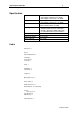
Specification and Index 9 Specification Inputs Outputs Indicators User Options 1 Laser Disc RF 75 Ω 0.5V p-p nominal 1 cable digital serial interface to SPDIF 1 optical digital serial interface to SPDIF 1 cable digital serial interface to SPDIF 1 optical digital serial interface to SPDIF Yellow LED for Power Red lock LED for AC-3 decoding Jumper Options to: 1. Disable 5V DC detection on RF input 2. Disable switching to digital audio inputs 3.