DVP1080 HD Digital Video Processor Installation and Operation Manual IMPORTANT: THE DVP1080 OFFERS MANY SETUP OPTIONS TO INSURE PROPER INTEGRATION WITH SOURCES AND DISPLAY DEVICES. PLEASE READ THIS COMPLETE MANUAL TO INSURE PROPER INSTALLATION AND OPERATION. ANSWERS TO MOST TECHNICAL QUESTIONS CAN BE FOUND HERE. INSTALLERS: PLEASE REVIEW THIS MANUAL BEFORE CONTACTING FAROUDJA TECHNICAL SUPPORT. PRODUCT OWNERS: PLEASE CONTACT YOUR AUTHORIZED FAROUDJA DEALER FOR PRODUCT OR INSTALLATION QUESTIONS.
TABLE OF CONTENTS QUICK START INSTALLATION GUIDE----------------------------- 4-5 SAFETY STATEMENT AND GUIDANCE --------------------------- 6-7 INSTALLATION AND CONNECTIONS ---------------------------- 8-10 UNPACKING ------------------------------------------------------------ 8 MOUNTING ------------------------------------------------------------ 8 SETUP MENU ----------------------------------------------------- 11-13 OPERATION INSTRUCTIONS ----------------------------------- 14-17 FRONT PANEL -----------
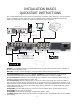
INSTALLATION BASICS QUICKSTART INSTRUCTIONS It is recommended that the entire manual be reviewed prior to installing video equipment. Here are the basic steps to install the DVP1080. Due to the long list of available setup options for the different sources and displays, it is important to review each component’s manual for proper operation.
QUICK START CONTINUED - MENU STRUCTURE ON-SCREEN-DISPLAY INPUT - SET: INPUT ENABLE / DISABLE SET FOR EACH INPUT INPUT ASPECT RATIO PROFILE RECALL PROFILE STORE SET: RGB INPUT SYNC SYNC-ON-GREEN/COMPOSITE SYNC PICTURE - BRIGHTNESS CONTRAST COLOR TINT DETAIL ADVANCED COLOR SET: OSD ON/OFF SET: OSD TIMER 0-255 (30 DEFAULT) DISPLAY - H-POSITION V-POSITION BLANKING LEVEL L/R BLANKING T/B BLANKING SET: LCD TIMER 0-255 (30 DEFAULT) PATTERNS - TEST PATTERNS PATTERN SELECT SET: BAUD RATE 9600/19200/57600
SAFETY PRECAUTIONS – Unplug this product from the wall outlet before cleaning. Do not use liquid cleaners or aerosol cleaners. Use a damp cloth for cleaning. – Do not use attachments not recommended by the product manufacturer as they may be hazardous. – Do not use this product near water. Do not use immediately after moving from a low temperature to high temperature, as this causes condensation, which may result in fire, electric shock, or other hazards.
– Unplug this product from the wall outlet and refer service to qualified service personnel under the following conditions: a) When the power supply cord or plug is damaged. b) If liquid has been spilled, or objects have fallen on the product. c) If the product has been exposed to rain or water. d) If the product does not operate normally by following the operating instructions.
1 3 4 2 7 5 8 6 11 9 NOT ACTIVE 12 10 INSTALLATION AND SETUP LEVEL 3 WARNING EXCESSIVE TEMPERATURE The internal temperature has reached the maximum limit. This warning will display for five seconds, then the unit will shut down and cannot be powered up by the Power button or Remote. UNPACKING Inspect product box and unit for any shipping damage. Save product box in the event the unit needs to be shipped in the future. Shipping the unit in a generic box may void warranty.
7. D15F COMPUTER PASS-THRU INPUT: Use with high scan rate analog signals to pass-through to the display device. (DVI Input Continued ) NOTE #2: Select the DVI INPUT [DVI/RGB] + [1] for the processor to “process” the signal to the selected output rate. Select PASS-THRU, press [PASS/TX] to display the signal without processing. NOTE #1: Signals connected to this input are not processed or transcoded (YPrPb to RGBHV).
(DVI output - Continued) Notes NOTE #2: With HDCP encrypted sources, it can take up to 30 seconds for the HDCP authorization between source and display to be acquired. The display device must be HDCP compatible to get an image. NOTE #3: Higher resolution displays require higher quality DVI cables. Using cables not rated for the resolution being used will result in images with colored sparkles and lines. Always verify maximum resolution rating of the cable with cable supplier.
SETUP MENU OVERVIEW: The SETUP Menu offers many selections to optimize the processor for installation. Be sure to completely review the menu items and application notes to insure proper operation. PRESS THE MENU KEY ON THE REMOTE FOR 7-SECONDS TO ENTER THE SETUP MENU menu seven seconds SETUP Menu functions are visible on the front panel, not on the On-Screen-Display. Use the directional buttons on the remote to navigate. SET: NTSC SCAN RATE This sets the output rate when a NTSC source is auto-detected.
SET:DVI INPUT 16-235 / 0-255 Sets the correct input signal level to match the DVI input source. NOTE #1: 0-255 is typical for digital display devices inputs (the processor output is 0-255), 16-235 is typical for video sources. However, not all sources follow the rules. If the processor DVI input level is set to 0-255 but the source is 16-235, the image will lack dynamic range. Note #2: To test what the output is from the source, put up a 10 step gray scale pattern from a test pattern DVD.
NOTES SET:1080i TO 1080P ENHANCED / HI-BANDWIDTH Sets how 1080i signals will be processed when the output rate is set to 1080p only. HI-BANDWIDTH mode has full bandwidth processing with no image adjustments (levels, aspect ratio, etc.). ENHANCED mode offers full image adjustment control at a slightly reduced bandwidth. NOTE #1: This function only applies to displays with a native resolution of 1920x1080p (or 9” CRTs) and with the DVP1080 set to the 1080p output scan rate.
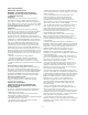
RESET POWER / STANDBY IR WINDOW LCD DISPLAY DVP1080 OPERATION FRONT PANEL CONTROLS Each time the processor is powered up, it will go through an initializing power-up sequence. RESET: In the event of a processor firmware lockup, insert a small paper clip into opening to reset. Stored profiles and system settings will not be erased. NOTE #1: Unplugging the unit from power source will accomplish the same task. POWER / STANDBY: Press to turn ON unit (LED Green), press again to put unit in STANDBY (LED Red).
REMOTE BUTTON OPERATION DIRECTIONAL BUTTONS: Press [MENU] to access the OSD. Press again to deactivate. Use the DIRECTIONAL keys to navigate through the OSD options. ON / OFF CONTROL: Press the [GREEN] button to turn on the unit, press the [RED] button to enter the standby mode. NOTE #1: To move to different OSD menu pages, press [MENU], then [UP/DOWN] until the top triangle turns yellow, then [RIGHT/LEFT]. A new MENU page will appear as they are selected.
BRIGHTNESS BUTTON: Adjusts the darkest areas of the screen. ASPECT RATIO BUTTONS: Each selects the proper aspect ratio of the source being viewed. Adjust so the shadows are as dark as possible but subtle details are still visible (such as seeing the wrinkles in a dark suit on a person standing in the shadows). Suggested test pattern: PLUGE NOTE #1: The proper screen shape must be set in the SETUP menu during initial installation in order for these settings to function properly. See page 10 for details.
OTHER OSD IMAGE ADJUSTMENTS RS 232 INSTRUCTIONS DISPLAY MENU PAGE The DVP Header, followed by a comma (no space), is used to delimit the Header from the Command. The following is an example, using Windows HyperTerminal, for Power On using a standard Modem Cable: IMAGE POSITION: Use to adjust the horizontal and vertical position of the image. NOTE #1: Many digital displays will not allow any image adjustments when using DVI.
RS232 CONTROL COMMANDS CODE RANGE DESCRIPTION OPERATION COMMANDS A# (0-2) 0=4x3,1=Letterbox, 2=Anamorphic B# (0-100) 50 default C# (0-100) 50 default D# (0-15) 04 default DVI EXT FST HELP K# (0-220) 50 default OFF ON P# (0-8) [1-8=User, 0=Factory] PM# (0-1) [0=Normal, 1=Bypass] R ST STHELP STNP# (1-8) STPP# (1-8) T# (0-100) 50 default V X Y Input Aspect Ratio Brightness Contrast Detail DVI Input Pass-through Input Report Current System Status Displays full list of commands for this unit Color Power OFF
SETUP COMMAND - CONTINUED: CODE RANGE DESCRIPTION RD RE SCRTRG# (0=Off, 1=ON) SETFT SRN# (1-12) SRNHELP SRP# (1-6) SRPHELP TB# (0-100) TPHLP STHELP VP # (0-20) 25 default VPOL# (0=Neg 1=Pos) W# (0=4:3, 1=Widescreen, 2=Wide 4:3) XD XE YD YE RGB Input Disabled RGB Input Enabled 12v Screen Trigger Restore Factory Defaults Scan Rate Selection NTSC Scan Rate Help Menu PAL Scan rate Selection PAL Scan Rate Help Menu Top Blanking Display Test Pattern Help Menu Setup Help Menu Vertical Position Vsync Polarity S
SPECIFICATIONS Processing 10-bit signal path 1080i deinterlacing with MADI and 3:2 pulldown High Bandwidth Mode: full resolution 1920x1080p (Straight deinterlacing without scaling) Enhanced mode: 1080i converted to 1280x720 resolution then scaled to the selected output rate Inputs Format NTSC/PAL(TBD) Composite(BNC) S-Video (4-pin DIN) Component (BNC) 480i/480p/720p/1080i 1v pp Y – 1v pp, C – 286mv pp Y – 1v pp(SMPTE) Cr – 700mv pp Cb – 700mv pp RGB (BNC) Comp.
FAROUDJA WARRANTY STATEMENT Faroudja®, a division of Genesis Microchip Inc. warranties that its products will substantially conform to published specifications, subject to the terms and conditions below. These warranties are limited to the first purchaser of the products (“Purchaser”) for the period listed below from the date of sale.
faroudja Rev:1-3/05