Issued 10-99 $2.50 DXP 195 Air Release and Hydraulic Release Parking Disc Brakes Maintenance Manual No.
Service Notes This publication provides maintenance and service procedures for Meritor's DXP 195 air release and hydraulic release parking disc brakes. The information contained in this publication was current at the time of printing and is subject to revision without notice or liability. 1. You must understand all procedures and instructions before you begin maintenance and service procedures. 2. You must follow your company's maintenance and service guidelines. 3.
Table of Contents Asbestos and Non-Asbestos Fibers Warnings ................................................................1 Section 1: Exploded View........................................................................................................2 Section 2: Introduction Description..............................................................................................................................4 Identification ..............................................................................
Notes
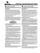
Asbestos and Non-Asbestos Fibers 1
Section 1 Exploded View Spring-Applied Air Release Brake (Left-Hand Brake) 6 5 8 4 7 9 10 3 1 2 Item Description Sequence Number * Item Description Sequence Number * 1 2 3 4 5 Chamber Pin Cotter Pin Spacer Lining Assembly 00100 00110 00120 00130 00140 6 7 8 9 10 Spring Retaining Pin Cotter Pin Washer Adjuster Plug 00150 00160 00170 00180 00190 * Sequence numbers appear in the bill of material available from the equipment manufacturer.
Section 1 Exploded View Spring-Applied Hydraulic Release Brake (Left-Hand Brake) 7 6 9 5 8 3 2 4 1 10 11 Item Description Sequence Number * Item Description Sequence Number * 1 2 3 4 5 6 Chamber Spacer Pin Cotter Pin Spacer Lining Assembly 00100 00105 00110 00120 00130 00140 7 8 9 10 11 Spring Retaining Pin Cotter Pin Washer Adjuster Plug 00150 00160 00170 00180 00190 * Sequence numbers appear in the bill of material available from the equipment manufacturer.
Section 2 Introduction Description Figure 2.1 The DXP 195 dry disc parking brake fits a 14.88-16.54-inch (378-420 mm) disc range and can be packaged as a driveline, wheel end or axle-mounted park brake. It is designed for use in off-highway haulers, mining vehicles, front-end loaders and various stationary machinery. • The brake features a lightweight single-piece cast caliper, supported on twin slide pins, which is fixed to a "universal" mounting saddle.
Section 2 Introduction Identification To identify the DXP 195 assembly, refer to the tag located on the chamber bracket. Figure 2.3. Figure 2.
Section 3 Disassembly Remove the Linings CAUTION WARNING To prevent serious eye injury, always wear safe eye protection when you perform vehicle maintenance or service. Do not work under a vehicle supported only by jacks. Jacks can slip or fall over and cause serious personal injury. Support the vehicle with safety stands. 1. Block the wheels of the vehicle to prevent the vehicle from moving. 2. If necessary, raise the vehicle. Support the vehicle with safety stands. 3.
Section 3 Disassembly 5. Remove the stabilizer bar cotter pin and retainer pin. Hinge the stabilizer bar so it is out of the way. Figure 3.3. Figure 3.3 Remove the Caliper Assembly CAUTION Do not use the stabilizer bar to lift the caliper on or off of the vehicle. Damage to the stabilizer bar can result. 1. Remove the brake linings. Refer to "Remove the Linings" in this section. 2. Remove the clevis pin from the lever. Figure 3.4. 3. Remove the chamber. Figure 3.4. 4. Remove the four saddle bolts. 5.
Section 4 Assembly Install the Caliper Assembly WARNING To prevent serious eye injury, always wear safe eye protection when you perform vehicle maintenance or service. Use Meritor parts only. Do not use parts manufactured by other suppliers. Use of non-Meritor parts can cause damage, loss of braking and serious personal injury. 1. Lift the caliper over the disc. • If you use shims: Install the shims in the positions you marked during removal. 2. Align the bottom caliper saddle bolt holes.
Section 4 Assembly Adjust the Initial Caliper Clearance 1. Adjust the caliper by reducing the caliper-to-disc clearance to ZERO. Refer to Table A for the adjusting direction. 4. Install the adjuster plug and washer. Tighten the adjuster plug to 8-12 lb-ft (11-17N•m). Figure 4.2. Figure 4.2 2. Check that the load plate fully contacts the lining backing plate. WASHER-ADJUSTER PLUG 3. Use a 6 mm Allen wrench to increase the disc clearance SEVEN CLICKS, which sets the initial clearance. Figure 4.1.
Section 5 Maintenance Hydraulic Fluid WARNING Use only the type of hydraulic fluid specified by the equipment manufacturer. Do not use different types of hydraulic fluid. Using incorrect hydraulic fluid will damage the rubber parts of the caliper. Component damage, loss of braking and serious personal injury can result. Do not reuse hydraulic fluid. Used fluid can be contaminated and cause incorrect operation. Serious personal injury can result.
Section 5 Maintenance 5. Measure the distance from the bottom of the chamber to the center of the clevis pin while the brakes are applied. Figure 5.1. Figure 5.1 MEASURE ADJUSTED CHAMBER STROKE Inspect the Brake Components WARNING Use Meritor parts only. Do not use parts manufactured by other suppliers. Use of non-Meritor parts can cause damage, loss of braking and serious personal injury. Lining Thickness Lining material thickness must not be less than 0.200-inch (5.1 mm).
Section 5 Maintenance Heavy Heat Checking Disc CAUTION You must always replace a damaged disc. 1. When you inspect the brakes, inspect both sides and the outer diameter of the disc for the following conditions: Heavy heat checking is surface cracks with width and depth. Figure 5.3. If you find heavy heat checking, always replace the disc. Figure 5.3 • Cracks • Heat checking • Grooves or scoring • Blue marks or bands 2. When you reline the brakes, you must measure the thickness of the disc.
Section 5 Maintenance Cleaning Blue Marks or Bands Blue marks or bands indicate that the disc was very hot. If blue marks or bands are present, refer to Section 6 to find and correct the cause of the problem. Figure 5.5. Figure 5.5 WARNING To prevent serious eye injury, always wear safe eye protection when you perform vehicle maintenance or service. Solvent cleaners can be flammable, poisonous and cause burns.
Section 5 Maintenance Cleaning Non-Metal Parts • Use soap and water to clean non-metal parts. • Scrape away build-ups of mud and dirt on the linings. Replace all linings contaminated with oil or grease. Drying Cleaned Parts • Dry the parts immediately after cleaning and washing. • Dry the parts with soft clean paper or rags. Corrosion Protection Apply rust inhibiting fluid to the cleaned and dried parts that are not damaged and are to be immediately assembled.
Section 6 Diagnostics DXP 195 Air Release and Hydraulic Release Parking Disc Brakes Conditions: ➀ Chamber exceeds two-inch maximum stroke requirement Possible Cause(s): Incorrect initial adjustment or inoperative automatic adjuster What to Check: Corrections: Check the chamber stroke If the air chamber still after 20 brake overstrokes, replace the applications. caliper/saddle assembly. Refer to Sections 3 and 4.
Section 7 Specifications Torque Specifications Component Torque Mounting Bolts 400-500 lb-ft (544-680 N•m) Chamber Nuts • Air Release Brakes • Hydraulic Release Brakes 135-155 lb-ft (180-210 N•m) 30-40 lb-ft (41-54 N•m) Adjustment Plug 8-12 lb-ft (11-17 N•m) 16
Notes
Information contained in this publication was in effect at the time the publication was approved for printing and is subject to change without notice or liability. Meritor Automotive, Inc., reserves the right to revise the information presented or discontinue the production of parts described at any time. Meritor Heavy Vehicle Systems, LCC 2135 West Maple Road Troy, MI 48084 U.S.A. 248-435-1085 800-535-5560 (North America only) www.meritorauto.com Meritor do Brasil Ltda. Av.