
User's Manual


6
Section 3
Disassembly
Remove the Linings
WARNING
To prevent serious eye injury, always wear safe
eye protection when you perform vehicle
maintenance or service.
Do not work under a vehicle supported only by
jacks. Jacks can slip or fall over and cause
serious personal injury. Support the vehicle with
safety stands.
1. Block the wheels of the vehicle to prevent
the vehicle from moving.
2.If necessary, raise the vehicle. Support the
vehicle with safety stands.
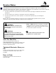
3. Remove the adjuster plug and washer from
the chamber bracket. Figure 3.1.
Figure 3.1
CAUTION
Use an Allen wrench to manually adjust and
de-adjust the brakes. Do not use an air gun to
adjust or de-adjust the brakes. Damage to
components can result.
Stop turning the Allen wrench when you feel
resistance. Do not continue to turn the Allen
wrench beyond the resistance point. Damage to
components can result.
NOTE:When you de-adjust the brake (increase
disc clearance), you will hear a "'clicking" sound
and feel a "pulsing" sensation during the
adjustment.
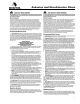
4. Use a 6 mm Allen wrench to de-adjust the
brake as specifiedon the brake caliper and in
Table Abelow.Stop turning the Allen
wrench when you feel resistance, which
indicates that the adjuster pistons are fully
retracted. Figure 3.2.
•To ensure that the automatic adjustment
will occur:Adjust the brake an additional
¼-turn after you reach the resistance
point.
WASHER-ADJUSTER PLUG
ADJUSTER PLUG
Figure 3.2
ALLEN
WRENCH
ALLEN
WRENCH
Table A: Increasing and Decreasing Disc Clearance
Caliper Identification Increase Disc Clearance Decrease Disc Clearance
LH Air Release Brake Assembly Counterclockwise Clockwise
RH Air Release Brake Assembly Clockwise Counterclockwise
LH Hydraulic Release Brake AssemblyCounterclockwise Clockwise
RH Hydraulic Release Brake AssemblyClockwise Counterclockwise