gomerlin.com.au gomerlin.co.
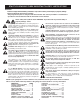
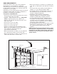
START BY READING THESE IMPORTANT SAFETY INSTRUCTIONS WARNING • Failure to comply with the following instructions may result in serious personal injury or property damage. • Read and follow all instructions carefully. • The garage door opener is designed and tested to offer safe service provided it is installed and operated in strict accordance with the instructions in this manual. These safety alert symbols mean WARNING : A possible risk to personal safety or property damage exists.
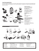
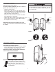
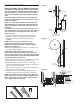
CARTON INVENTORY Your door opener is packaged in one carton which contains the opener and the parts illustrated below. Note that accessories will depend on the model purchased. If anything is missing, carefully check the packing material.
PREPARING YOUR DOOR Before you begin: To prevent possible SERIOUS INJURY or DEATH: • ALWAYS call a trained door systems technician if door binds, sticks or is out of balance. An unbalanced door may not reverse when required. • NEVER try to loosen, move or adjust door, door springs, cables, pulleys, brackets or their hardware, ALL of which are under EXTREME tension. • Disable ALL locks and remove ALL ropes connected to the door BEFORE installing and operating the door opener to avoid entanglement.
DOOR REQUIREMENTS Survey the area to see if any of the conditions below apply to your installation. Additional materials may be required. You may find it helpful to refer back to this page as you proceed with the installation of your opener. Depending on your requirements, there are several installation steps which may call for materials or hardware not included in the carton. This opener is compatible with: • Doors that use a torsion bar, springs and a door no more than 4.2m (14’) high.
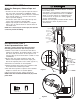
ASSEMBLY STEP 1 Attach the Collar to the Opener To avoid installation difficulties, do not run the door opener until instructed to do so. • Loosen the collar screws. • Attach collar to either the left or the right side of the opener. Depending on Left or Right hand installation ensure that the collar is seated all the way on motor shaft until stop is reached (Figure 1). • Position the collar so that the screws are accessible when attached to the torsion bar.
INSTALLATION IMPORTANT INSTALLATION INSTRUCTIONS WARNING To reduce the risk of SEVERE INJURY or DEATH: 1. READ AND FOLLOW ALL INSTALLATION WARNINGS AND INSTRUCTIONS. 2. Install door opener ONLY on properly balanced and lubricated the door. An improperly balanced door may not reverse when required and could result in SEVERE INJURY or DEATH. 3. ALL repairs to cables, spring assemblies and other hardware MUST be made by a trained door systems technician BEFORE installing opener. 4.
INSTALLATION STEP 2 Attach the Emergency Release Rope and Handle To prevent possible SERIOUS INJURY or DEATH from a falling door: • If possible, use emergency release handle to disengage door ONLY when door is CLOSED. Weak or broken springs or unbalanced door could result in an open door falling rapidly and/or unexpectedly. • NEVER use emergency release handle unless the doorway is clear of persons and obstructions.
INSTALLATION STEP 4 Figure 1 Attach the Cable Tension Monitor (Required) Your MJ3800 is supplied with a cable tension monitor. This safety device is supplied to monitor the cable for ANY slack that may occur and will reverse the door when excessive slack is detected, eliminating service calls. The cable tension monitor MUST be connected and properly installed before the door opener will move in the down direction. NOTE: The cable tension monitor is shipped for left side installation.
To prevent possible SERIOUS INJURY or DEATH from electrocution or fire: • Be sure power is not connected to the opener, and disconnect power to circuit BEFORE removing cover. • Door installation and wiring MUST be in compliance with ALL local electrical and building codes. • NEVER use an extension cord, 2-wire adapter or alter the plug in any way to make it fit outlet. Be sure the opener is grounded.
INSTALLATION STEP 7 Install The Protector SystemTM Be sure power is not connected to the door opener BEFORE installing the safety reversing sensor. To prevent SERIOUS INJURY or DEATH from a closing door: • Correctly connect and align the safety reversing sensor. This required safety device MUST NOT be disabled. • Install the safety reversing sensor so beam is NO HIGHER than 100mm (4”) above the floor.
CONNECT ELECTRIC POWER TO AVOID INSTALLATION DIFFICULTIES, DO NOT RUN THE GARAGE DOOR OPENER UNTIL INSTRUCTED TO DO SO. Connect to properly fused and earth power outlet. INSTALLATION STEP 8 Mounting the Evercharge Standby Power Unit (SPU) TM CM475 EverCharge Standby Power Unit If the CM475 Standby power supply unit is part of this installation it should be installed at this time. • The SPU can be mounted to either the ceiling or a wall within 3' (.9 m) of the opener.
AUTOMATIC CLOSE TIMER FUNCTION Note: Requires the Chamberlain Protector SystemTM (IR-sensors) to be installed. If Protector SystemTM (IR-sensors) is installed to enable the timer to close function (first time), install sensors, close the garage door and wait for 5 minutes. A Multi-function Door Control is required to enable and disable the auto-close function. Enable: Push and hold lock button on the Multi-function Door Control until the electric lock toggled twice.
ADJUSTMENT STEP 1 Program the Travel Limits Without a properly installed safety reversal system, persons (particularly children) could be SERIOUSLY INJURED or KILLED by a closing door. • NEVER learn forces or limits when door is binding or sticking. Repair door first. • Incorrect adjustment of the door travel limits will interfere with proper operation of safety reversal system. • After ANY adjustments are made, the safety reversal system MUST be tested.
ADJUSTMENT STEP 2 Setting the Force The force setting button is located on the front panel. The force setting measures the amount of force required to open and close the door. 1. Locate the orange button on the unit (Figure 1). 2. Push the orange button twice to enter unit into Force Adjustment Mode (Figure 2). The LED (Indicator Light) will flash quickly. 3. Push the transmitter, wireless wall button or multi-function door control (Figure 3). The door will travel to the DOWN (close) position.
ADJUSTMENT STEP 5 Test the Safety Reversal System Without a properly installed safety reversal system, persons (particularly children) could be SERIOUSLY INJURED or KILLED by a closing the door. • Safety reversal system MUST be tested every month. • If one control (force or travel limits) is adjusted, the other control may also need adjustment. • After ANY adjustments are made, the safety reversal system MUST be tested. Door MUST reverse on contact with 40mm (1 1/2”) high obstacle on the floor.
OPERATION IMPORTANT SAFETY INSTRUCTIONS WARNING To reduce the risk of SEVERE INJURY or DEATH: 1. READ AND FOLLOW ALL WARNINGS AND INSTRUCTIONS. 2. ALWAYS keep transmitters out of reach of children. NEVER permit children to operate or play with the wireless wall button, multi-fucntion door control or transmitters. 3. ONLY activate the door when it can be seen clearly, it is properly adjusted and there are no obstructions to door travel. 4. ALWAYS keep the door in sight until completely closed.
WIRELESS PROGRAMMING Your door opener has already been programmed at the factory to operate with your hand-held transmitter. The door will open and close when you press the large centre button. Below are instructions for programming your opener to operate with additional Security+ transmitters.
TO ADD, REPROGRAM OR CHANGE A KEYLESS ENTRY PIN USING THE “LEARN” BUTTON 1. Press and release the orange “learn” button on opener. The learn indicator LED will glow steadily for 30 seconds. 2. Within 30 seconds, enter a four digit personal identification number (PIN) of your choice on the keypad. Then press and hold the ENTER button. 3. Release the button when the opener LED turns off. 3 To change an existing, known PIN If the existing PIN is known. 1.
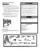
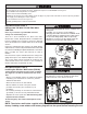
REPAIR PARTS Installation Parts 1 6 5 2 7 NOT ICE 8 4 3 KEY NO. 1 2 3 4 5 PART NO.
“Learn” Button LED or Diagnostic LED “Learn” Button Diagnostic Chart 1 FLASH Safety reversing sensors wire open (broken or disconnected). OR 2 FLASHES Safety reversing sensors wire shorted or black/white wire reversed. 3 FLASHES multi-function door control or wire shorted. 4 FLASHES Safety reversing sensors slightly misaligned (dim or flashing LED). 5 FLASHES Possible RPM sensor failure. Unplug to reset. 9 FLASHES Cable tension monitor reversal.
TROUBLESHOOTING 1. The opener doesn't operate from either the multifunction door control, wireless wall button or the transmitter: • Does the opener have electric power? Plug a lamp into the outlet. If it doesn't light, check the fuse box or the circuit breaker. (Some outlets are controlled by a wall switch.) • Have you disabled all door locks? Review installation instruction warnings on page 7. • Is there a build-up of ice or snow under the door? The door may be frozen to the ground.
OPERATION OF YOUR OPENER Your merlin® Security+ opener and hand-held transmitter have been factory-set to a matching code which changes with each use, randomly accessing over 100 billion new codes. Your opener will operate with up to 64 merlin® Security+ transmitters and one Keyless Entry System. If you purchase a new transmitter, or if you wish to deactivate any transmitter, follow the instructions in the Programming section.
CHAMBERLAIN LIMITED WARRANTY Merlin® Professional MJ3800 Sectional Garage Door Opener Chamberlain Australia Pty Limited / Chamberlain New Zealand Limited (Chamberlain), the manufacturer of Merlin® automatic garage door openers, is committed to manufacturing and supplying high quality goods. As part of this commitment, we seek to provide reliable service and support for our goods and are pleased to provide you, the original purchaser, with this Chamberlain Limited Warranty.